Templot Club Archive 2007-2020
|
|||
| author | remove search highlighting | ||
|---|---|---|---|
|
posted: 11 Mar 2010 09:04 from: kenbec
click the date to link to this post click member name to view archived images |
I have decided to standardise with all of my switches using flexible points (not loose-heel) if this is technically feasible. Before I go any further on this basis I would like answers to the following if possible. 1. Would these switches be structurally sound or is there likely to be distortion in the points because of the light structure of the metal used. (Peco code 80 nickel silver)? 2.Has anyone used this point structure on their layout and if so which point motors have you used? I am replacing Peco Switches which are operated by either Peco or SEEP motors, both of which work satisfactorily on the Peco Switches but which I feel will be a bit sudden Would these motors be powerful enough to bend the points to the necesseray curve and hold them in place? I suspect the locking mechanism would fail. Are there any recommendations for alternatives? 3.How are the tiebars attached? Obviously they must be insulated electrically. Is it the usual practice to use a PCB suitably modified with the actuating rod soldered to it? Not great for appearance but practical? I would appreciate any answers. Regards, ken |
||
|
posted: 11 Mar 2010 20:43 from: Jim Guthrie
click the date to link to this post click member name to view archived images |
Ken, I use spring blades on all my pointwork - using Code 125 BH, Code 95 BH and Code 40 FB. It works very well. The spring of each blade effectively cancels the other out when you couple the blades together with the tiebar. It is worth trying to arrange matters so that the blades assume a "halfway" position when the tiebar is attached so that there is no bias one way or the other on the force required to move the blades. The blades should be hinged in some way to the tiebar so that the blade tips can rotate and flex slightly when the switch is operated. I have seen some people just soldering switch blades directly to a PCB tiebar but I suspect these will come adrift sometime with the forces involved at the blade tips. A motor driven point motor like the Tortoise is a lot kinder to pointwork than the solenoid type. Solenoid types can work spring blades perfectly well but the forces generated can cause breakages with tiebars or the loosening of stock rails at the switch. I would go for the Tortoise style of point motor if you can. Jim. |
||
|
posted: 11 Mar 2010 21:13 from: MikeTrice click the date to link to this post click member name to view archived images |
The following articles on RMWeb might be of interest: http://www.rmweb.co.uk/forum/viewtopic.php?f=8&t=42746 http://www.rmweb.co.uk/forum/viewtopic.php?f=5&t=37908&start=25 http://www.rmweb.co.uk/forum/viewtopic.php?f=8&t=46997 |
||
|
posted: 11 Mar 2010 21:43 from: kenbec
click the date to link to this post click member name to view archived images |
Jim Guthrie wrote: Jim, It is worth trying to arrange matters so that the blades assume a "halfway" position when the tiebar is attached so that there is no bias one way or the other on the force required to move the blades.An excellent point which I could easily have missed. The blades should be hinged in some way to the tiebar so that the blade tips can rotate and flex slightly when the switch is operated. I have seen some people just soldering switch blades directly to a PCB tiebar but I suspect these will come adrift sometime with the forces involved at the blade tips.Hmm! Could be tricky in N gauge as everything is so small but I can see what you mean. I have a couple of ideas though and because things are so small the arc the points have to travel will also be very small so less strain on any fittings I hope. A motor driven point motor like the Tortoise is a lot kinder to pointwork than the solenoid type.Yes I thought this would be the case. Thank you for this information it helps me a lot to get the advice of experienced track builders. Not being an engineering type I need all the help I can get so I keep copies and I am building up quite a reference library. ken |
||
|
posted: 11 Mar 2010 22:27 from: Nigel Brown click the date to link to this post click member name to view archived images |
I use both flexible and loose heel switches, with no problems (3mm scale, code 60 B/H rail). I'd go along generally with what has been said above; I lay both switch rails in the closed position, with the correct running-rail path for each, so that when moved in a bit and attached to the tie bar there's no bias either way. The tie-bar's a piece of upside down gaped pcb with a couple of holes drilled in appropriate positions, small brass pins pushed through the holes from the bottom, bent over 90 degrees then soldered along the bottom of the inner side of the rail. I suspect there's something better to use than PCB as the copper bit isn't needed and requires gaping, but I can't think what. Point motors are Tortoise. I did decide recently to try servos and ordered some kit from The Bouncer, but haven't had anything back; anyone any experiences in this direction? |
||
|
posted: 12 Mar 2010 02:29 from: kenbec
click the date to link to this post click member name to view archived images |
MikeTrice wrote: The following articles on RMWeb might be of interest:They are indeed, expect more questions when I have had a chance to absorb the contents. regards, ken |
||
|
posted: 12 Mar 2010 02:58 from: kenbec
click the date to link to this post click member name to view archived images |
Nigel Brown wrote: I use both flexible and loose heel switches, with no problems (3mm scale, code 60 B/H rail). I'd go along generally with what has been said above; I lay both switch rails in the closed position, with the correct running-rail path for each, so that when moved in a bit and attached to the tie bar there's no bias either way. Nigel, The tie-bar's a piece of upside down gaped pcb with a couple of holes drilled in appropriate positions, small brass pins pushed through the holes from the bottom, bent over 90 degrees then soldered along the bottom of the inner side of the rail. I suspect there's something better to use than PCB as the copper bit isn't needed and requires gaping, but I can't think what. I was at a bit of a loss at how to go about it although I did think something like this was a possibility, Mike Trice refers to something similar at http://www.rmweb.co.uk/forum/viewtopic.php?f=8&t=46997 I would be very interested also if there is an answer to the following. Point motors are Tortoise. I did decide recently to try servos and ordered some kit from The Bouncer, but haven't had anything back; anyone any experiences in this direction?Thank you for your input, I am learning more with every answer. ken |
||
|
posted: 12 Mar 2010 08:01 from: Jim Guthrie
click the date to link to this post click member name to view archived images |
Ken, Here's another method which might interest you - with the tiebar underneath the track base. This method is quite popular with a good few people. 25_120244_240000000.jpg 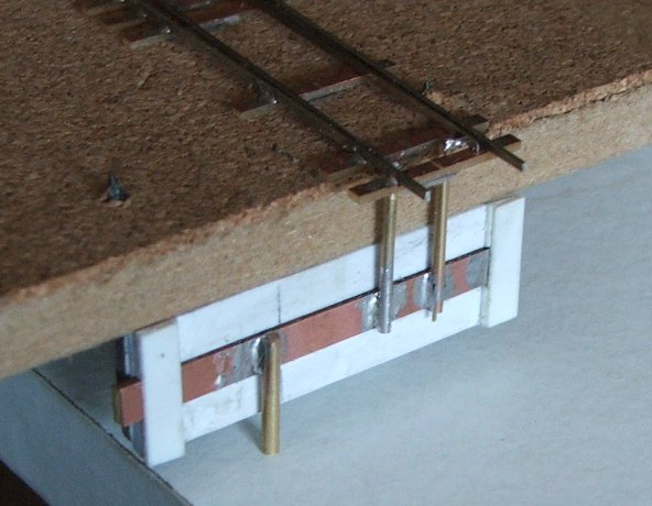 25_120245_420000000.jpg 25_120245_420000000.jpg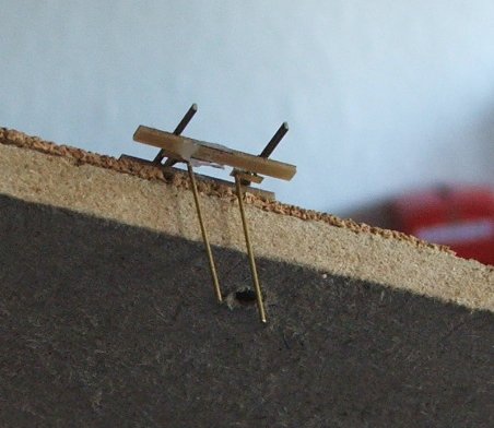 25_120245_030000000.jpg 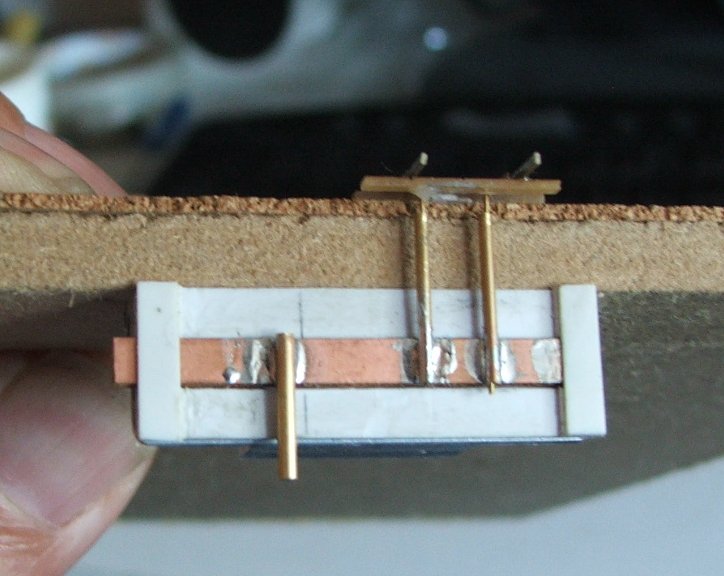 Three views of a test turnout I built in FS160 (finescale N) using 2mm society Code 40 wire rails and PCB timbering. Brass wire is soldered to the switch blades (which are sprung) and extend through the track base to the turnout operating unit. In this case I've soldered short pieces of brass strip to the underside of the blades and these strips extend under the stock rails to keep the switch blades vertically aligned to the stock rails. The wires are soldered into holes drilled in the inner ends of these strips. This track was for street trackage so everything bar the rails would be hidden. For normal track you might want to make a less obvious joint to the underside of the switch blades. The TOU is made from Plastikard strip, a bit of 4mm PCB turnout timbering and some brass tube to be not too tight a fit on the brass wire. The lot is glued to a short bit of B&Q alloy section to allow mounting to the track base. The tube and wire gives the hinge action. This method allows you to fit scale cosmetic tiebars. Jim. |
||
|
posted: 12 Mar 2010 09:27 from: kenbec
click the date to link to this post click member name to view archived images |
Jim said,Here's another method which might interest you - with the tiebar underneath the track base. This method is quite popular with a good few people.Ingenious and with care could be installed quite inconspicuously. I like the idea of the tubing which should allow some free play while the switch is moving. I have it in my mind that the two wires will traverse slightly different arcs in which case too tight connections could impose some stresses. Am I raving? Not being familiar with Tortoise motors (I must get one to familiarise myself), I have to ask would this system be usable with one? In this case I've soldered short pieces of brass strip to the underside of the blades and these strips extend under the stock rails to keep the switch blades vertically aligned to the stock rails.This I think would be essential wouldn't it? This is one of the first things that I thought could be a problem with spring (flexible) points. ken |
||
|
posted: 12 Mar 2010 10:38 from: Dellboy
click the date to link to this post click member name to view archived images |
Jim Guthrie wrote:
A very nice arrangement Jim, simple effective design, easily removable, and using the PCB vertically gives strength to the soldered joints. Methinks the best one I've seen so far so I might try it out for myself. I am mostly using mechanical lever frames with WIT control so would extend the length of the PCB sufficiently to allow for drilling a hole in the end for the linkage wire. I can't see it in the picture but a cut across the PCB copper would isolate the switch blades from each other. Derek |
||
|
posted: 12 Mar 2010 11:08 from: Jim Guthrie
click the date to link to this post click member name to view archived images |
Dellboy wrote: Spot the obvious mistake. These TOUs are actually used with tube in wire operation. The alloy section from B&Q is a "U" section - you can just see the bottom face of the "U" section in the picture. On this part is mounted a crank with a slot on one of its arms to engage the third bit of pipe on the PCB strip. 25_120602_100000000.jpg 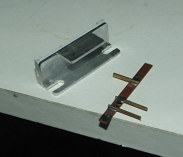 Here's a shot of the bit of hacked about "U" section. The slots are for the two holding screws and allow the lateral adjustment of the TOU. The other side of the "U" is cut back to allow easy access to the holding screw heads and this provides a platform for the operating crank. The crank pivots on an 8 or 10BA screw in a tapped hole in the alloy. There is just enough meat in the alloy section to allow tapping and a lock nut is used to fix the screw in position. Jim. Jim. |
||
|
posted: 12 Mar 2010 11:23 from: Dellboy
click the date to link to this post click member name to view archived images |
Jim Guthrie wrote: Spot the obvious mistake.I like the arrangement even more, certainly the best one I have seen. Derek |
||
| Last edited on 12 Mar 2010 11:24 by Dellboy |
|||
|
posted: 13 Mar 2010 00:33 from: kenbec
click the date to link to this post click member name to view archived images |
Jim Guthrie wrote: ,Here's another method which might interest you - with the tiebar underneath the track base. This method is quite popular with a good few people.Jim, In an earlier reply I asked if this worked with a Tortoise point motor, on closer examination it seems this set up is designed for a wire and tube operation. So that was a rather silly question. I will have too many widely spread apart turnouts to adopt this approach. Regards ken |
||
|
posted: 13 Mar 2010 01:28 from: kenbec
click the date to link to this post click member name to view archived images |
MikeTrice wrote: The following articles on RMWeb might be of interest:Mike, They certainly are. The information contained is so comprehensive that I don't really have much to ask you. You really have gone into it in depth. I have picked up a lot from your jigs and the crossing angle templates will be very handy. One question does arise and that is why you found it necessary to cut insulating gaps just below the V in the wing rails of the turnout in the first link. Secondly how did you anchor the nickel silver wire when you changed from the Peco track pins on the tiebar for the three way turnout. The Peco pin had a head which would have held it in place, the wire didn't seem to have anything which would serve the same purpose. Also I have been searching high and low for 3 point gauges suitable for Peco code 80 track, would yours suit and if so where did you get them? I am using Peco code 80 track because I have boxes of it accumulated from various sources over many years, actually enough to do my whole anticipated layout, and don't intend to change from that. Thank you for pointing me to your excellent mine of information which I am sure I will refer to on many occasions, ken |
||
|
posted: 13 Mar 2010 10:44 from: Jim Guthrie
click the date to link to this post click member name to view archived images |
Kenneth Beckett wrote: Ken Here's a picture of the same idea but with a Tortoise motor driving the sub-trackbase tiebar. 25_130526_430000000.jpg 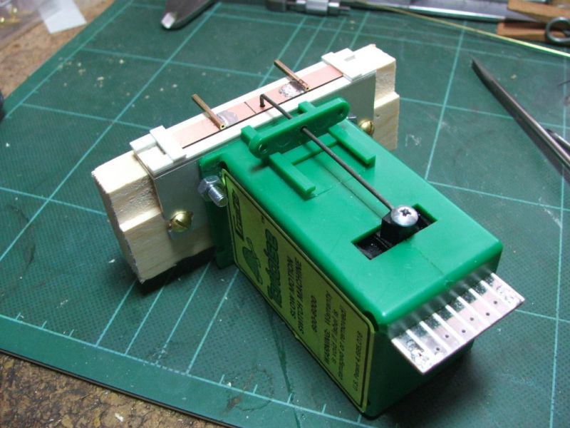 This is for a Scale7 layout so is a bit chunkier than the N scale version. In this case the Tortoise drives straight on to the tiebar, but there are many other ways of connecting the Tortoise to the tiebar which might better suit your purposes. There's also the normal health warning when using Tortoise motors - they are big. The above setup is just under four inches tall - from the edge connector on the motor to the surface which mounts on the underside of the track base. So you would need quite deep baseboards to accommodate this arrangement. But you can make, or purchase, right angle mounts to hold the motor on its side which reduces the sub-track base depth. I also built another Scale7 layout some years ago where the Tortoise motors were mounted on their sides on a board at the back of the layout and light alloy tube (again from B&Q) was used to connect to the sub base tiebars. The mounting board for the Tortoises was set a bit below the track base level and the Tortoises were placed on top of this so the linkage lined up with the sub-base tiebars and the bulk of the Tortoise motors was projecting into the space above the track bases and was hidden behind scenery/backscenes. There are other "slow motion" point motors which are much lower profile than the Tortoise and you might want to investigate them if you are pushed for space to fit Tortoises. Jim. |
||
| Attachment: attach_758_1073_tortoise02.jpg 1630 | |||
|
posted: 13 Mar 2010 15:40 from: MikeTrice click the date to link to this post click member name to view archived images |
Kenneth Beckett wrote: One question does arise and that is why you found it necessary to cut insulating gaps just below the V in the wing rails of the turnout in the first link. To answer each each question in turn: 1. Cutting the insulating gaps as illustrated results in the switches being insulated from each other (reducing the possibility of shortcircuits) and from the vee. Each switch is connected electrically to its corresponding stock rail so does not depend on the switch contacting the stock rail to work. The polarity of the vee is controlled by a DPDT electrical switch. 2. Instead of the head of the pin, the new pin relies on the small 90degree bend. See http://www.rmweb.co.uk/forum/viewtopic.php?f=8&t=46997#p735929 which shows the new pin in the same orientation as the Peco pin on the right. 3.The three point gauge is made by Micro Engineering. Mine are code 55 ones but a quick check against some Peco Code 80 track suggests they would suit nicely. I bought mine from here: http://www.handlaidtrack.com/tools-supplies-track-gauges-c-9_37.php and would thoroughly recommend their service. Also bought my 0.5mm solder from them. You might also like to consider the following: http://www.rmweb.co.uk/forum/viewtopic.php?f=11&t=51055 One thing I cannot stress enough is that you need good quality templates to the standards you intend to build to. If you intend to use Templot be aware that Templot does not plot the outside edge of the flatbottom rail which makes location of the rail difficult. Martin does have a workaround which a search of this forum should find. |
||
|
posted: 14 Mar 2010 11:09 from: kenbec
click the date to link to this post click member name to view archived images |
Jim Guthrie wrote: KenJim, There are other "slow motion" point motors which are much lower profile than the Tortoise and you might want to investigate them if you are pushed for space to fit TortoisesThey are big aren't they? I had already started investigating SmartSwitch, Fulgurex and Switchmaster point motors, I will see how they shape up. The Tortoise sounds really good but probably for a larger gauge layout. Some of my turnouts are close together and it could get very crowded although the Tortoise design does seem to lend itself to setting the up in remote positions. I will see how things turn out. You have obviously put a lot of time and thought into using Tortoises and I thank you for giving me the benefit of your efforts. Regards, ken |
||
|
posted: 14 Mar 2010 11:46 from: kenbec
click the date to link to this post click member name to view archived images |
MikeTrice wrote: 1. I have been used to dealing with Peco Insulfrog turnouts, I just realised these are Live Frog (so obvious really, I just wasn't thinking before I asked). 2. I like this method very much, it is very suitable for N Scale. 3. This is good news, I have already contacted Fast Tracks (Hand Laid Tracks?). By shear fluke whilst browsing the other day I discovered an interesting NEM specification under 310/311 (http://www.morop.org/de/normes/nem310-311_d_bbl2.pdf). Close examination of the specification revealed this is exactly what I was after. Reading the small print I realised this was a product made by Tillig under part number 08961.The site mentioned in your link seems to be telling me in French that it is no longer available. If you intend to use Templot be aware that Templot does not plot the outside edge of the flatbottom rail which makes location of the rail difficult. Martin does have a workaround which a search of this forum should find.I wasn't aware of this. Thank you very much for the "heads up". You have given me a lot of helpful information not the least of which has been making me fully aware of the existence of the RM site. Thanks again, ken |
||
|
posted: 14 Mar 2010 15:08 from: MikeTrice click the date to link to this post click member name to view archived images |
The site that fails is the Morop site, not the suppliers of Tillig. Try International Models, they were very helpful in getting mine. Alternative url: http://www.morop.org/de/normes/nem310_bbl2_d.pdf |
||
| Last edited on 14 Mar 2010 16:59 by MikeTrice |
|||
|
posted: 6 Apr 2010 12:02 from: kenbec
click the date to link to this post click member name to view archived images |
MikeTrice wrote: Sorry to go back so far but I just received my Tillig 08961 gauges today which International Models was kind enough to organise for me. In your article at http://www.rmweb.co.uk/forum/viewtopic.php?f=11&t=51055 you say They are very similar to the NMRA gauge in use and do come with extensive instructions showing all aspects of the gauges use.Well the ones I received do have extensive instructions but they are in German. As the only German I understand is after it has been translated into English I am wondering if you received an English version of the instructions. Could you please let me know? By a coincidence the FastTracks three point gauges also arrived today, thanks for your help here as well. ken |
||
| Last edited on 6 Apr 2010 12:03 by kenbec |
|||
|
posted: 6 Apr 2010 20:48 from: MikeTrice click the date to link to this post click member name to view archived images |
if you received an English version of the instructions. No, mine are German as well however I was able to work it out from the copious diagrams. The photos in http://www.rmweb.co.uk/forum/viewtopic.php?f=11&t=51055 show the major functions. |
||
| Last edited on 6 Apr 2010 20:50 by MikeTrice |
|||
|
posted: 7 Apr 2010 05:17 from: kenbec
click the date to link to this post click member name to view archived images |
MikeTrice wrote: I thought they might be.if you received an English version of the instructions. The photos in http://www.rmweb.co.uk/forum/viewtopic.php?f=11&t=51055 show the major functions.Yes they have been quite useful. Thanks, ken |
||
| Please read this important note about copyright: Unless stated otherwise, all the files submitted to this web site are copyright and the property of the respective contributor. You are welcome to use them for your own personal non-commercial purposes, and in your messages on this web site. If you want to publish any of this material elsewhere or use it commercially, you must first obtain the owner's permission to do so. |