Templot Club Archive 2007-2020
|
||||
| author | remove search highlighting | |||
|---|---|---|---|---|
|
posted: 19 Jul 2010 20:32 from: Ian Spalding click the date to link to this post click member name to view archived images |
I'm trying to find out how stretcher bars on double slips were connected to either a point lever or to point rodding. I have drawings of how the stretcher bars are connected to the switch rails. But were the stretchers at one end of the slip connected together and then to the point lever/ rodding or were they driven separately or what? Principally interested in pre-grouping LSWR and LNWR but any prototype information would be appreciated. Regards, Ian Spalding |
|||
|
posted: 21 Jul 2010 16:37 from: Ian Spalding click the date to link to this post click member name to view archived images |
Ian Spalding wrote: I'm trying to find out how stretcher bars on double slips were connected to either a point lever or to point rodding. I have drawings of how the stretcher bars are connected to the switch rails. But were the stretchers at one end of the slip connected together and then to the point lever/ rodding or were they driven separately or what? Principally interested in pre-grouping LSWR and LNWR but any prototype information would be appreciated.Partly answered my own question by looking around the Templot site and finding a drawing of a 1:7 GER double slip posted by Martin on 29/07/2009. Here the two stretchers at one end have separate point rods. What date was the drawing? At least it's a start. Any other information? Regards, Ian Spalding |
|||
|
posted: 21 Jul 2010 16:56 from: Martin Wynne
click the date to link to this post click member name to view archived images |
Hi Ian, In most cases both sets of blades at one end of a double slip are linked and work together. This is always* the case when they are rodded from a signal box and part of the interlocking. This is convenient in a model because the drive working all 4 blades can also be used to switch the crossing polarity at the opposite end of the slip. Sometimes in yards where they are worked by hand levers they may have separate levers for each set of blades -- this makes the levers easier to work, of course. In some designs of double slip it is not physically possible to drive them separately because there is insufficient room between the wing rails to have both blades open simultaneously. *I can't believe I wrote "always", but I honestly don't know of any case of an interlocked slip with separate drives. But someone will. regards, Martin. |
|||
|
posted: 25 Jul 2010 15:42 from: philchudley click the date to link to this post click member name to view archived images |
Hi All Had a look at the weedstrewn Woking (ex SR /LSWR) down yard Friday and confirm all the double slips there are indeed worked by two handlevers, and a single tie bar for both sets of blades Some of these are still worked as part if the yard is for handling of stone/aggregate trains and for the stabling of track machines. Cheers Phil Chudley Martin Wynne wrote: Hi Ian, |
|||
|
posted: 21 Nov 2010 10:24 from: JFS
click the date to link to this post click member name to view archived images |
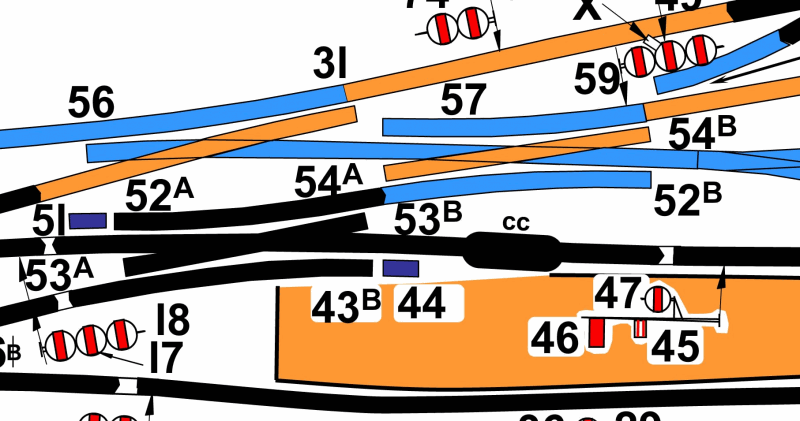
Martin Wynne wrote: *I can't believe I wrote "always", but I honestly don't know of any case of an interlocked slip with separate drives. But someone will. Sorry it has taken me a while to reply to this... Well, you did ask for it Martin - but the reality is that practice varied from company to company, and guess what, the GWR *always* linked "double compounds" the other way - that is, when a slip was part of two crossovers, the one diagonally opposite pair of blades were worked by the same lever, and thus the pairs of blades at the same end were worked independently. (there now I used the word "always...") Herewith a section of the box diagram at Exeter West to prove the point(s) - it is not the easiest diagram to read but if you follow what levers 52,53,54 do you will see what I mean. Most other companies would only have used 2 levers to deliver the same functionality. The LNWR would have used 4 (with not a single ground signal anywhere in the layout!). 1129_210621_500000000.png  Hope this helps. Regards, Howard |
|||
| Last edited on 21 Nov 2010 11:24 by JFS |
||||
|
posted: 21 Nov 2010 10:25 from: JFS
click the date to link to this post click member name to view archived images |
Oops, sorry about the image size! - how do I resize it? | |||
|
posted: 21 Nov 2010 11:33 from: Martin Wynne
click the date to link to this post click member name to view archived images |
JFS wrote: Oops, sorry about the image size! - how do I resize it?Hi Howard, Use the Image Gallery for pictures -- for Internet Explorer and Firefox the buttons are in the posting editor just above the text area*. The image will be automatically resized, and anyone wishing to see the full size version can do so via the Gallery (by looking for your images, i.e. click J for JFS in the alphabetical links). I have now changed it for you. The attachments on messages are intended for non-image files -- Templot .box data files, etc. You are limited to one attachment per message, but you can insert as many images as you like via the Gallery. *for other browsers, right-click on the image in the Gallery and then copy the URL (image location). Enter it in your message between img tags like this:
regards, Martin. |
|||
|
posted: 21 Nov 2010 13:37 from: JFS
click the date to link to this post click member name to view archived images |
Many thanks for that Martin. Regards, Howard |
|||
|
posted: 22 Nov 2010 12:19 from: BeamEnds click the date to link to this post click member name to view archived images |
Purely based on empirical evidence, of Toton, Andover and Sailsbury yards, I'd venture that the SR and at least some of its constituents used 4 levers on a non-controlled double slips. | |||
|
posted: 22 Nov 2010 14:33 from: JFS
click the date to link to this post click member name to view archived images |
.. but, based on the box diagrams for Portsmouth Yard, Portsmouth Harbour and others I am fairly sure that the SR's general practice was to connect as Martin suggested where the slips were worked from lever frames. I have been looking for pictures showing ground connections (since that was Ian's original query), but so far have come up with nothing. But there must still be some mechanically worked double slips at places like Worcester / Shrewsbury etc - who do we know who lives near enough to go and have a look??? Regards, Howard |
|||
|
posted: 24 Nov 2010 02:40 from: BeamEnds click the date to link to this post click member name to view archived images |
Which is why I said non-controlled!! The question was for both - "But were the stretchers at one end of the slip connected together and then to the point lever/ rodding....". Earlier replies suggested that the controlled slips have only two tie bars, I was merely daring to suggest that non-controlled slips appear to be treated differently. I was specifically answering his question as the three yards I mention are all SR, and I've worked them, for all I know may have been LSWR. |
|||
|
posted: 24 Nov 2010 10:20 from: JFS
click the date to link to this post click member name to view archived images |
Sorry if I appeared to be arguing against you - I was only pointing out that the practice of how the ends were worked varied - even in the single case of working from rodding. I am still trying to find some pics of how they were physically connected to the rod run. My memory of layouts I have been around in the past is that there were two separate stretchers each with a separate drive rod incorporating a turnbuckle adjustment but which were then connected to a common bellcrank and thence to the rodding run. It seems to me that a single stretcher connected to four blades would be subject to an unreasonable degree of stress - but I was wrong once before:-) In the 1980's I worked at Wolverton Works and at that time the Haversham Bank sidings, although heavily overgrown, were still entirely intact - including double slips apently - all LNWR trackwork, but the area was cleared years ago. Needless to say, I took no photos... Howard |
|||
|
posted: 25 Nov 2010 19:49 from: JFS
click the date to link to this post click member name to view archived images |
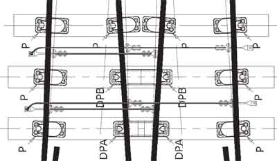
I failed to find a photo, but I did find this in the Exactoscale instructions. 1129_251446_580000000.jpg  It is a bit of a simplification but shaows the principle. It makes an interesting comparison with the GER drawing. Hope this helps. Regards, Howard |
|||
| Please read this important note about copyright: Unless stated otherwise, all the files submitted to this web site are copyright and the property of the respective contributor. You are welcome to use them for your own personal non-commercial purposes, and in your messages on this web site. If you want to publish any of this material elsewhere or use it commercially, you must first obtain the owner's permission to do so. |