Templot Club Archive 2007-2020
|
|||
| author | remove search highlighting | ||
|---|---|---|---|
|
posted: 1 Jan 2011 08:02 from: polybear click the date to link to this post click member name to view archived images |
Hi all, I'm in the process of making a B8 R/H Turnout using Bullhead rail; it's 4mm and using copperclad sleepers with Masokits etched brass chairs. My question is: what is the best way to accommodate the tips of the switch blades where they meet the stock rails? Put a "set" in the curved stock rail? And if so should I do this in the straight stock rail also? Or go for joggles - in one or both rails? What are the best ways of creating both these methods please, and how to judge when it's the correct amount of "set" or "joggle"? My interest lies with ex-LNER/LMS, late 50's to early 60's. However, my first priority is for good reliable running, even if it means using a technique which wasn't commonplace at this time (I think joggles were more a pre-grouping technique?) Many thanks. Brian |
||
|
posted: 1 Jan 2011 10:49 from: Martin Wynne
click the date to link to this post click member name to view archived images |
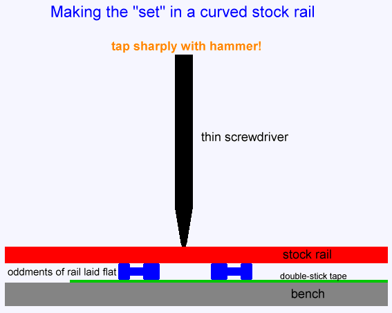
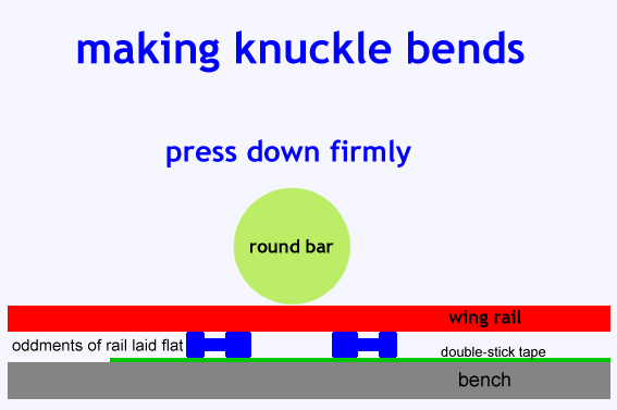
polybear wrote: My question is: what is the best way to accommodate the tips of the switch blades where they meet the stock rails? Put a "set" in the curved stock rail? And if so should I do this in the straight stock rail also? Or go for joggles - in one or both rails?Hi Brian, It's either a plain set in the turnout side stock rail only (undercut switch planing), or a joggle in both rails (straight-cut switch planing). That's not just for pre-grouping, it's for all bullhead. GWR and BR(W) used joggles throughout. Other companies used the REA designs with joggles in running-line facing turnouts only, and a plain set in other turnouts. This shows a plain set, thanks to Rod Cameron for the photo: stock_rail_rea.jpg  It's very difficult to make an accurate prototypical joggle. A set in one side only is much easier to model, and the easiest way to make it is: 2_041840_270000000.png  2_041828_140000000.png  Hopefully the diagrams are self-explanatory. Just two bits of rail about an inch long laid side by side with a gap between. The smaller the gap, so the harder you need to press/hit, but the more precisely located will be the bend. Make sure the rail is exactly square across them before making the bend -- a sheet of graph paper underneath helps. For details of how to do this and get the correct angle, see this topic on here: topic 491 and this post of mine and the links on Old RMweb: http://www.rmweb.co.uk/forum/viewtopic.php?p=771350#p771350 copied here: You must have either a plain set, or a joggle. If you simply curve the stock rail, it will be impossible to fit the point blades to gauge. Sometimes folks call a set a joggle, so it's not always clear what is meant. For the GWR and BR(W), joggles and straightcut-planed switch blades were used instead of a plain set in all cases. For other companies, facing switches in bullhead running lines were usually fitted with straightcut-planed switches and corresponding joggled stock rails, even on non-GWR lines. The REA bullhead designs used by other companies include both patterns of switch planing -- undercut/set for trailing locations; straightcut/joggled for facing locations. The straightcut switch blades are 3/8" thick at the tip and very much more robust than the undercut blades used in trailing locations (not on the GWR and BR(W), where all switches are straightcut/joggled). Visitors to the Severn Valley Railway at Kidderminster can very easily observe the difference between joggled and unjoggled switches. In platform 1 the engine release turnout at the buffer stops has an REA semi-curved flexible switch with undercut-pattern switch blades (set, no joggle): joggle-3.gif  rea_no_joggle1.jpg  rea_no_joggle2.jpg  __________________________________ Across in platform 2 the engine release turnout has a GWR curved flexible switch with straightcut-pattern blades and joggled stock rails. The very much more robust nature of the blade tips in this case is very evident: joggle-1.gif  gwr_joggle1.jpg  gwr_joggle2.jpg  __________________________________ Notice that in the undercut switch (upper two pictures) the blades are not shiny on top at the tip -- they serve only to guide the wheel flange, not to support the wheel, at the tip. In the straightcut switch (lower two pictures) the shiny tops run all the way to the tip, supporting the wheel along the full length of the planing. This is the way to identify switches in photos. If the open blade is shiny all the way to the tip, it is almost certainly a straightcut/joggled switch. More info and diagrams at: http://www.templot.com/martweb/gs_realtrack.htm#joggle Modelling information is at: topic_491&forum_id=1 A simple way of making the set is at: topic_492&forum_id=6 regards, Martin. |
||
|
posted: 1 Jan 2011 12:16 from: Nigel Brown click the date to link to this post click member name to view archived images |
A simple way of making something close to a "joggle" is of course to file away a bit of the inside face of the stock rail to provide a bed for the switch rail to fit into. Particularly useful in smaller scales where there are limits to how thin you really want the switch rail tip to be. Cheers Nigel |
||
|
posted: 1 Jan 2011 13:18 from: Martin Wynne
click the date to link to this post click member name to view archived images |
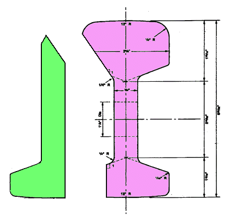
Nigel Brown wrote: A simple way of making something close to a "joggle" is of course to file away a bit of the inside face of the stock rail to provide a bed for the switch rail to fit into. Particularly useful in smaller scales where there are limits to how thin you really want the switch rail tip to be.Hi Nigel, Only the extreme top corner needs to be a knife edge. The rest of the switch blade can be quite robust at the tip. This is a simple model approximation to undercut planing for use with a plain set: 2_010801_470000000.png  The switch blade needs to be reasonably robust at the tip in model flexible switches so that it opens to a full flangeway clearance all along its length. If the tip is too thin and fragile, only the end section will flex to the open position. If you adopt a filed "joggle" it is important not to make it a sharp notch. Wheel flanges can catch on this on the open side when running in the trailing direction, especially on curved turnouts. This is a prototype objection to joggles too -- it can lead to rough running in the trailing direction. regards, Martin. |
||
|
posted: 1 Jan 2011 16:30 from: Nigel Brown click the date to link to this post click member name to view archived images |
Hi Martin Agreed, about the sharp notch. I file it so that it's similar to a joggle. Re the switch thickness, I have in mind code 60 bullhead for 3mm scale, which is fairly flexible to start with; I prefer not to take chances. And yes, the top part of the rail is filed pretty thin, but not to a knife edge. Cheers Nigel |
||
|
posted: 2 Jan 2011 16:59 from: Judi R
click the date to link to this post click member name to view archived images |
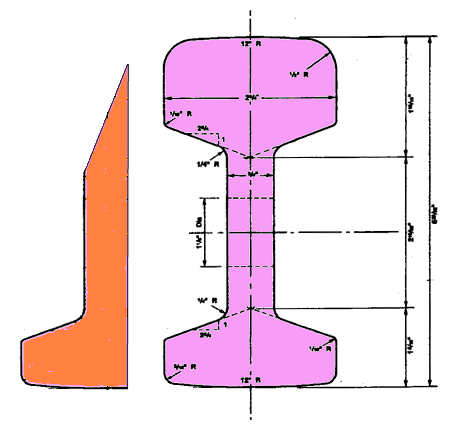
Martin Wynne wrote:Only the extreme top corner needs to be a knife edge. The rest of the switch blade can be quite robust at the tip. This is a simple model approximation to undercut planing for use with a plain set: As an alternative, you could try this profile: 1932_021155_110000000.gif  ... which maintains full web thickness for both stock and switch rails and minimises the gauge narrowing problems. Judi |
||
|
posted: 2 Jan 2011 17:10 from: Martin Wynne
click the date to link to this post click member name to view archived images |
Hi Judi, Thanks for that. The problem with the chamfered style of planing which you show there is that it is very difficult to do in model form. Almost all model rail section has a significantly over-scale web thickness, which limits the scope for tucking the switch rail under the head of the stock rail. And it is very difficult to make the undercut planed angle on the stock rail head using only hand tools. The angle on the switch rail top, and its height, also need to be precisely matched to the stock rail. I have never seen a model version of chamfered planing in the smaller scales, although there is always a first time of course. Anyone? regards, Martin. |
||
|
posted: 2 Jan 2011 21:31 from: polybear click the date to link to this post click member name to view archived images |
Hi Martin/all, Many thanks for the excellent reply! I've spent the afternoon trackbuilding and have used the above technique to create a set in the curved stockrail - significantly overdoing it in the process! It's surprising just how little a "tap" is required in order to create the "set". I couldn't visualise 1:32 & 1:24 angles so I converted them: 1.79 degrees for B switches, and 2.39 degrees for A switches. Hopefully more progress tomorrow. Regards, Brian Tulley |
||
| Please read this important note about copyright: Unless stated otherwise, all the files submitted to this web site are copyright and the property of the respective contributor. You are welcome to use them for your own personal non-commercial purposes, and in your messages on this web site. If you want to publish any of this material elsewhere or use it commercially, you must first obtain the owner's permission to do so. |