Templot Club Archive 2007-2020
|
|||
| author | remove search highlighting | ||
|---|---|---|---|
|
posted: 12 Jan 2014 04:27 from: Murryb
click the date to link to this post click member name to view archived images |
I have finally reached a point where I would like some comments on the attached layout(O Gauge) please excuse the drawings for the station but you will get the idea. Bit more to go into the yard and at the top to join up with a traverser.What would be the minimum size switch in the yard. It has been a challenge to get this far, the printer has been well used and certain pages well thumbed. I did make the mistake of starting and then leaving things for a while, the memory cells needed prodding. Thanks Murry |
||
| Attachment: attach_1710_2376_Temuka_mirror_01.box 266 | |||
|
posted: 12 Jan 2014 08:14 from: Jim Guthrie
click the date to link to this post click member name to view archived images |
Murryb wrote: I have finally reached a point where I would like some comments on the attached layout(O Gauge) please excuse the drawings for the station but you will get the idea. Murray, Are you happy with the 53.9" minimum radius on PRO58 - which is possibly getting a bit tight for 7mm scale? You might be able to move the crossover a bit to the right to get the PRO58 turnout on to a larger radius on the curve, but that has knock-ons to other turnouts. I seem to be forever designing continuous layouts in small spaces where curved turnouts are the norm, and you start to get a sense for the pinch points which can occur. Jim. |
||
|
posted: 12 Jan 2014 08:48 from: Murryb
click the date to link to this post click member name to view archived images |
Jim Thanks for the comment. I can only see LNWR 6 wheels 30ft coaches being the longest on the layout Might need to move everything around to the right ie along the single track. I increased the centre on the double out to 90mm in case longer coaches appear . Could shorten the Platform. Murry |
||
|
posted: 12 Jan 2014 10:12 from: Martin Wynne
click the date to link to this post click member name to view archived images |
Hi Murry, Thanks for uploading your plan. It's looking good. The crossover on the left TR084 / TR107 is using D-7 turnouts. That's a rather unusual size combination, leading to an unnecessarily tight inner radius of 1367mm (53.8") on TR084. If you change TR084 to say C-9, that radius will increase to 1830mm (72.1"). You could then make TR107 a C-9 or B-9, and the overall length of the crossover will be about the same as before. If you use the F5 mouse action to adjust the turnout sizes, Templot will keep you to the more common size combinations. Generally for sharply curved crossovers, C-10 is a good size to choose, although in this case it would make the crossover a bit longer. regards, Martin. |
||
|
posted: 12 Jan 2014 11:42 from: Nigel Brown click the date to link to this post click member name to view archived images |
Might not be possible in whatever space you've got, but if you did a mirror image of the plan your facing turnouts become trailing, which might be more prototypical. Cheers Nigel |
||
|
posted: 13 Jan 2014 07:55 from: Murryb
click the date to link to this post click member name to view archived images |
Thanks for the replies Martin, I was not happy with the crossover as it is so will try what you suggest. Nigel, the trains on the inner line run to the left so the turnouts will be trailing? the original design was the other way around ie the double tracks on the right but was changed to this design so the double tracks could in future go outside, dreams are free. When I have altered things in the next week I will re-submit.The more I play around with templot the more I like it. Murry |
||
|
posted: 13 Jan 2014 11:28 from: Pierre
click the date to link to this post click member name to view archived images |
Hello Murry, With regard to your request for comment on your layout plan. Perhaps you should let us know what you are trying to achieve with your layout. It is a little difficult to make comment on a layout design without having some idea of the builders aims; I have no idea where you are on your personal model railway journey. You mentioned the LNWR, 30’ coaches and a traverser. To some that may indicate a layout theme based on the LNWR in pre-grouping times or perhaps branch line operation in post grouping (LMS) days, when those carriages would still have been in revenue service. The use of a traverser indicates perhaps storage for a number of trains with which you may seek to operate a prototypical sequence of trains on your model railway. Are you seeking to achieve some sort of prototypical operation ? A little more information would probably elicit and greater and more interesting response from the group. Best regards, Pierre |
||
|
posted: 14 Jan 2014 06:35 from: Murryb
click the date to link to this post click member name to view archived images |
Hi Pierre What I am looking at is a LNWR branch and I have taken the plan from Llanrwst& Trefriw and add double tracks at one end, as for prototypical operation that is a possibility. This will most likely be the only layout I will build so has to look reasonable good and provide interest over time. I have a large barn and 1.5 acres.the idea of the traverser is storage and to join up with the double track leading outside and the single line branching off ie like the Bethesda Jn on the NORTH WALES LINE. Murry |
||
|
posted: 15 Jan 2014 05:50 from: Pierre
click the date to link to this post click member name to view archived images |
Murry, I did a little research into the station at Llanrwst and the junction at Bethesda. The only track (and signalling) plan I could find on-line was from BR times in 1960, see link below: http://www.6g.nwrail.org.uk/llanwrstone.jpg and a nice picture from the 1930s. See link: http://www.6g.nwrail.org.uk/llanrwstonefin.jpg I also found a reference in the UK Loco Shed Index which says that there was a single road loco shed at Llanrwst, built in 1867 and closed in 1881. Unfortunately the 1960 era track plan does not show the shed or where it may have been. See link: http://locosheds.co.uk/index.php?n=Sheds.LLANRWST As far as the junction at Bethesda; I did find (on line) some late BR diagrams c1960s thru 1990s which show initially a standard dual track single line junction as per the Board of Trade (BOT) recommendations and later a simplified ladder junction and later still the junction is removed completely. So my guess is that it was (in later LNWR and LMS days) a standard dual track single line junction. When I look at your Templot plan I can see roughly how it has developed. You have copied the major aspects of the prototype plan however; as Nigel has hinted in his response, when you flipped the plan to its mirror image you have lost a very basic aspect of UK prototype practice wherein the trains drive on the left hand track and facing points were avoided where possible. I hope that you find my comments constructive and that I am not rehashing things that you may already well know. Best regards, Pierre |
||
| Last edited on 15 Jan 2014 06:28 by Pierre |
|||
|
posted: 15 Jan 2014 23:20 from: Murryb
click the date to link to this post click member name to view archived images |
Pierre I did not know about the trains driving on the left hand track, the photo is very helpful did not know about that webb site. My information comes from the following titles The Conway Valley Line (W G Rear), John Swift collection Vol 10 published by the Signalling Record Society. Looks like I have to do a mirror image or change the mirror image and make the approach to the yard as single track in the prototype and the other end double or have it all single as in the prototype. The engine shed was removed in 1881 and the 42ft turn table installed at Lanberis Murry |
||
|
posted: 17 Feb 2014 09:20 from: Murryb
click the date to link to this post click member name to view archived images |
I have now completed a much revised version of my original plan one of my questions is how to join two or more templates so they become one. I have a suspicion its something to do with grouping. Also what is the sketch board for? It has been an interesting learning curve. Thanks Murry |
||
| Attachment: attach_1759_2376_Temuka_C.box 205 | |||
|
posted: 17 Feb 2014 19:05 from: Martin Wynne
click the date to link to this post click member name to view archived images |
Murryb wrote: I have now completed a much revised version of my original plan one of my questions is how to join two or more templates so they become one. I have a suspicion its something to do with grouping.Hi Murry, You can't join templates so that they become one. If you did that the new template would have say two V-crossings and Templot would have no way of knowing what to do when you adjust the template's V-crossing angle. Likewise with all the other controls and settings. You can sometimes replace two templates with one. For example if two adjoining templates have the same radius, you could delete one of them and extend the length of the other to replace it. This is often the case when temporary dummy templates are used in the the make transition function for example. I imagine you are asking for the ability to move or rotate several templates in one go, or join them to other tracks? You can do that by selecting them all as members of a group. You will find all the functions in the group menu on the trackpad, and in the group menu on the storage box. Usually the easiest way to select them is to drag a fence rectangle around them. There is a button for that on the top row: 2_171324_170000000.png  It goes green when clicked. You can have only one group selected at a time. But you can easily re-select a previous group by giving the group members a prefix tag on the template name. More about that here: topic 2098 Also what is the sketchboard for?There are two work areas in Templot: 1. On the trackpad you design the details of your tracks and print them out as full-size track construction templates, usually on multiple pages. 2. On the sketchboard you can add details of the scenery and buildings to your track plan to create a colourful full layout plan, usually on a single page. This could be to show to friends, or include in a magazine article or club newsletter, or to post on a web forum such as this, etc. Or you can add colours and labels to make a control panel diagram, say. You can even use the sketchboard to create a greetings card or club leaflet, without any track at all. Here I have added a few items to your track plan on the sketchboard. This took only a minute or two: 2_171345_250000000.png 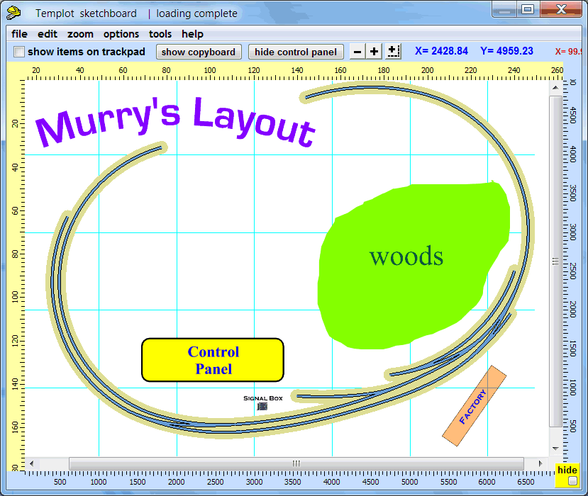 2_171345_260000001.png 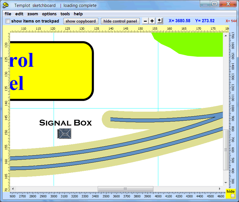 2_171345_260000002.png 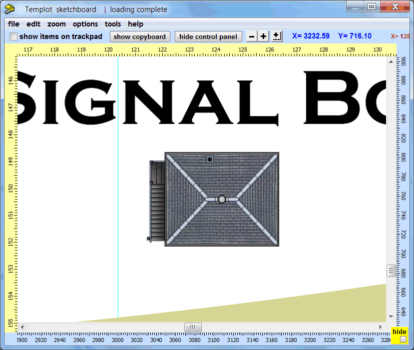 If you have a well-specified computer you can also have the sketchboard items showing on the trackpad, as an aid to the track design work. Be aware that this can significantly slow down the screen response for zooming and panning: 2_171419_140000000.png 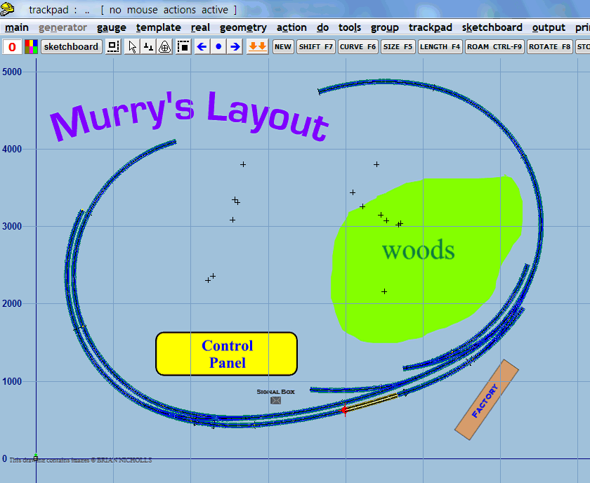 2_171419_150000001.png 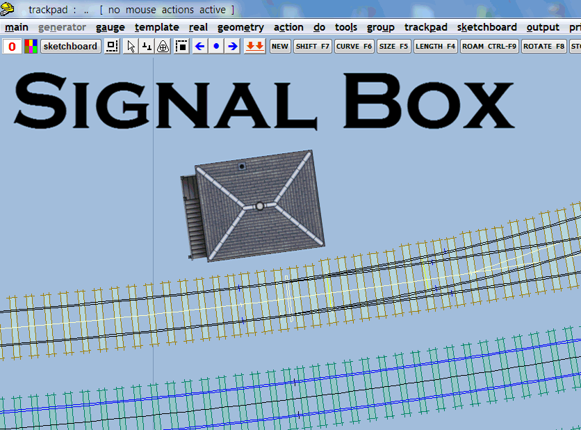 regards, Martin. |
||
|
posted: 18 Feb 2014 01:29 from: Murryb
click the date to link to this post click member name to view archived images |
Martin Thank you for the reply, Obviously you didn't notice any glaring mistakes so will complete the yard and top end. My next problem will be to obtain the necessary bits to start track construction. Will have to look up the O Gauge Product directory. |
||
| Please read this important note about copyright: Unless stated otherwise, all the files submitted to this web site are copyright and the property of the respective contributor. You are welcome to use them for your own personal non-commercial purposes, and in your messages on this web site. If you want to publish any of this material elsewhere or use it commercially, you must first obtain the owner's permission to do so. |