Templot Club Archive 2007-2020
|
|||
| author | remove search highlighting | ||
|---|---|---|---|
|
posted: 3 Oct 2014 22:50 from: Andrew Duncan
click the date to link to this post click member name to view archived images |
Hello Martin, one and all. I've uploaded some images of my progress on the trackwork for Yeovil Pen Mill so far. Progress has been pretty slow of late as I'm building the shed where the layout is going to live as well at the moment and this from scratch, so until that is finished further track making will be limited. The photos are all of the MPD between the junction. I'm going to try to lay it and ballast at the same time which the more I think about it the more nerve racking it is. I'll report back once I've summoned up the courage to put sleeper to wood glue... 2787_031707_450000000.jpg 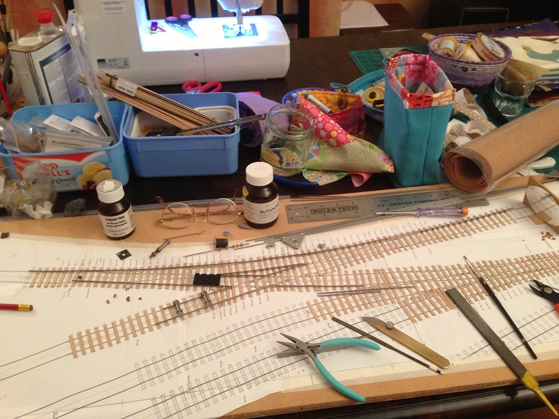 Early stages with most of the timbers in place and some rail laid in. At this early stage I was constructing the crossings in situe. I've now copied the idea of a chap on this site who makes all the crossings bonded to the wing rails with thin brass strip unsoldered underneath which makes a very solid job of it! 2787_031702_460000000.jpg 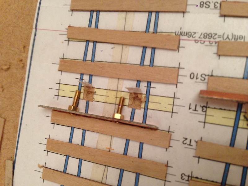 A friend, Dave Doe, told me in no uncertain manner that my ideas of using bent wire to provide the hinge for the loose heeled switches was very poor engerneering practice and generally a no no. I conceded defeat and actually found using 8BA or 10BA nuts soldered to the bottom of the sleeper rather satisfying to do. The appropriate bolt recessed bolt in the sleeper top produces the hinge to which the rail is soldered. 2787_031704_250000000.jpg 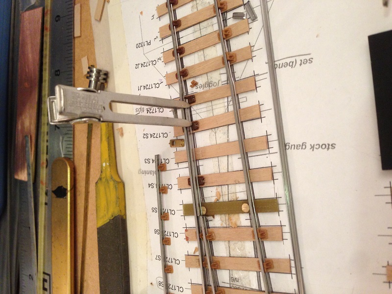 and here is the switch blade about to be soldered in position. 2787_031705_320000000.jpg 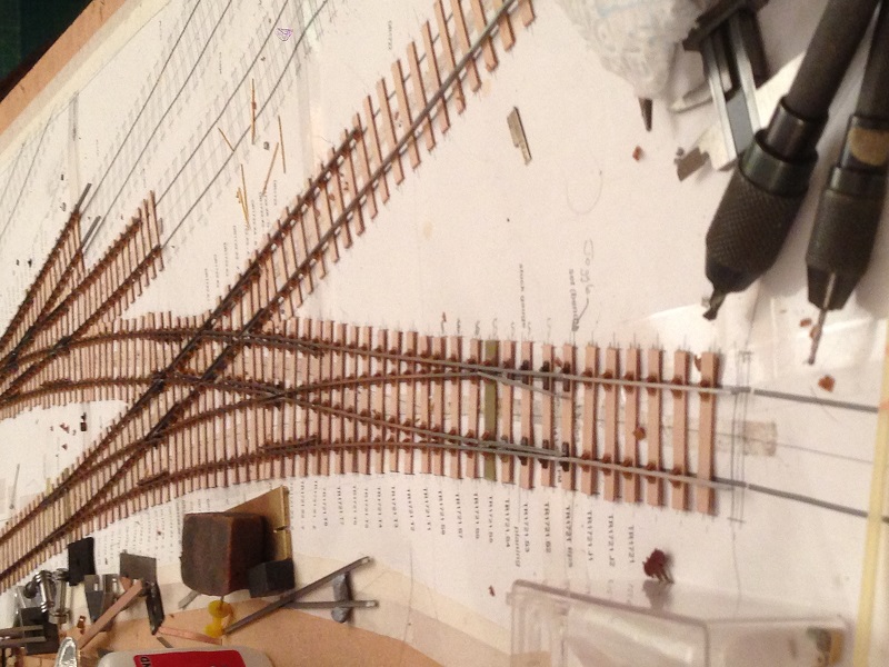 this shot shows the basic point work in an almost finished state. Just the trackwork to finish and crossing wires installed, before taking outside to spray. It also shows in exaggerated form, the distinctive dogleg produced by the loose heel of the switch. 2787_031658_470000000.jpg 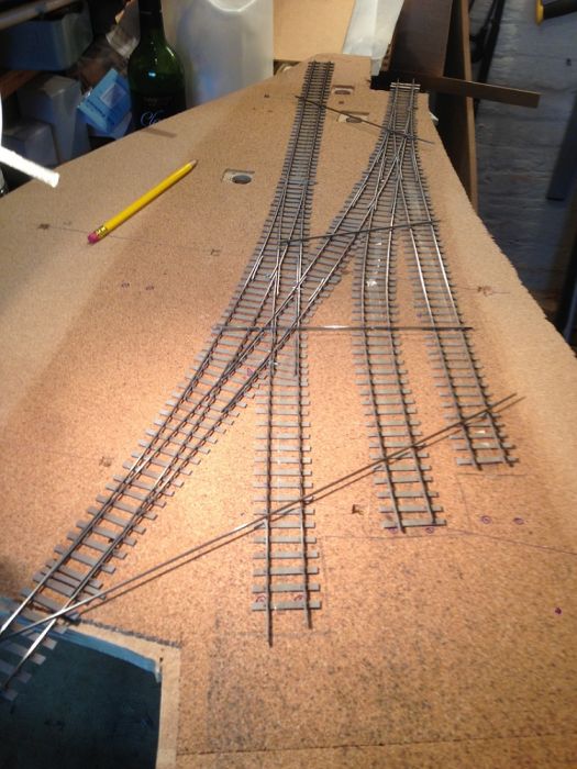 Sprayed and wired, the track is very fragile in this state so I took a tip from Iain rice and soldered some rail across the point work to reinforce it . All I've now got to do is get up the courage to lay it in a bed of glue and ballast it all in one just like Norman Solomon!! Martin I'm aware that this isn't strictly 'correct' continuing in 'Baffled beginners' part of the forum. Would you prefer that I put this under track building topic instead? If so, is it possible to move it if it is more relevant elsewhere? Kind regards and thanks for this really fantastic program. Andrew |
||
|
posted: 3 Oct 2014 23:14 from: Martin Wynne
click the date to link to this post click member name to view archived images |
Hi Andrew, Good to see your progress. As you can see, I have moved your message to start a new topic. Your previous topic on track planning Yeovil Pen Mill is at: topic 2326 regards, Martin. |
||
|
posted: 10 Oct 2014 22:28 from: Richard_Jones
click the date to link to this post click member name to view archived images |
Hi Andrew Very impressed.... Keep up the good work best wishes Richard |
||
|
posted: 25 Oct 2014 22:45 from: Andrew Duncan
click the date to link to this post click member name to view archived images |
Hello Richard and Martin Thanks for the encouraging and kind comments. Much appreciated Kind regards Andrew |
||
|
posted: 26 Sep 2015 19:12 from: Andrew Duncan
click the date to link to this post click member name to view archived images |
Yeovil Pen Mill update Sept 2015 I thought I'd post a couple of pictures of my progress in the garden, even if layout progress has been minimal in the last 6 months or so. The shed for the layout was quite a challenge. not having ever built anything this size from scratch before(22' x 11') I thought at various points over the last year (I started it in August 2014) that I'd bitten off more then I could chew. But I seem,with quite some help from my middle daughter Jeanne, to have almost got there now. It's even got power and heating in it but as you can see from the interior shot, with a work bench and a band saw, there isn't room to finish the baseboards which will go down the centre of the room! Ho hum. 2787_261334_500000000.png 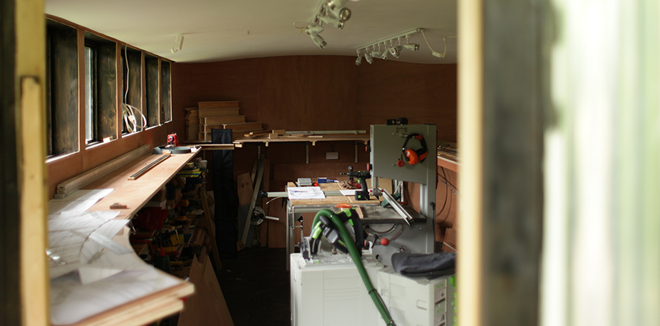 2787_261338_200000000.png 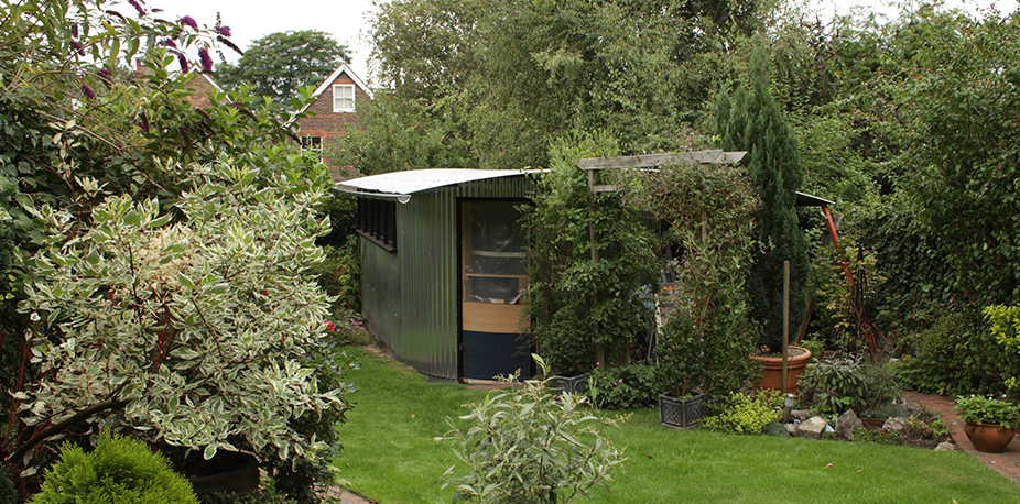 This shot shows the very wide roof which over shoots on the right hand side(hidden by the bushes) by 4' to provide cover under it for garden tools etc. I'll report more as time and progress dictate. Kind regards Andrew |
||
|
posted: 19 Feb 2017 20:58 from: Andrew Duncan
click the date to link to this post click member name to view archived images |
Hello Everyone I've started to make a little more progress now with Yeovil track work. I've still not stuck down and ballasted the MPD track to its baseboard for a variety of reasons, but I have built the next base board joining the MPD which is the double junction board. I thought it might be of interest to describe the methods I've used for this as its rather different to the approach that I started to take with the MPD. With that I'd built the track on sleepers double sided to the paper templates with the intention of removing the template at the end (which I did) and then laying the lot "Norman Solomans style " in one go and ballasting...job done! Well I still haven't plucked up the courage to do this, so... I then got interested in Howards Bolton's method of building track with the crossings pre fabricated directly on a spare template which in part is what I've followed in this next board which you'll see in the photos below. I say partly because I'd already stuck down the sleepers with double sided tape again intending to do the same as I had before. This time however I did not remove the template at the end of the track building, I just lifted it off its temporary construction board and stuck it in place with some "3M stuff" (does anyone know of an alternative glue that sticks well but allows adjustment before it goes off?) that did not swell the paper and sticks like the proverbial. This time I've stuck it directly to the baseboard (another departure from before when I used 3mm cork) which is 12mm MDF sealed with a coat of paint to prevent / reduce swelling and shrinkage which in turn is mounted on four 90mm high supports which in turn sit on the layout sub base(18mm ply). Why did I go for such a complicated set up? My need / requirement here is to have the layout broken up into sections 3' to 4' long so that I can build each section in the comfort of our main living room and so that if there any problems in the future I can remove a section from the main layout in the shed and bring it into the house to work on. Luckily for me I'm married to a pretty tolerant woman who still seems to be very fond of me despite my rather eccentric hobby. Maybe its something to do with her training as a psychotherapist, I think I'm probably an interesting case study for her...can't otherwise understand why she should put up with a bit of trainset on the end of our dining table week in week out? Anyway domestic arrangments apart, back to the layout. Here are few pictures of what Ive been describing above...if I can recall how to upload? 2787_191503_490000000.jpg 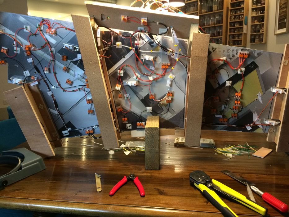 This view shows the underside wiring including the servos for turnouts controlled by the Megapoints electronics which seem rather like magic to me....! 2787_191512_420000000.jpg 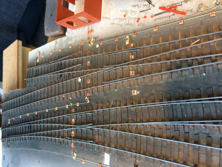 Yeovil point rodding under construction last month. Unlike Howards point rodding mine doesn't have to work luckily, as even this non working set up took an age to do. Incidentally I used Modelu point rodding stools which really are quite exquisite models (if only I could see all the detail!) Howards cranks, compensators etc and Eileen's metre long 0.4mm straight brass wire( this may have been a mistake as I've since read that brass gets damaged easily and perhaps nickel silver would have been stronger). I'm getting rather strange effects on the computer screen now so I think I'll quit whilst I'm ahead and try and upload this as it is. Kind regards Andrew |
||
|
posted: 20 Feb 2017 06:45 from: Martin Wynne
click the date to link to this post click member name to view archived images |
Hello Andrew, Many thanks for the update. Good to see such progress. It's nice to see the rodding being built into the pointwork as you go. On many layouts this gets left to last and considered part of the scenic department. And since no-one commented on your shed, may I add belatedly that looks to be a very inviting place to build a railway. And the pictures are a pleasant reminder of summer, on what here was a very grey day. regards, Martin. |
||
|
posted: 20 Feb 2017 16:37 from: Nigel Brown click the date to link to this post click member name to view archived images |
Thought the shed looked inviting as well. What form of heating are you using for it? Cheers Nigel |
||
|
posted: 20 Feb 2017 18:29 from: Andrew Duncan
click the date to link to this post click member name to view archived images |
Hello Martin Thanks for your comments on both the point rodding and the shed. it probably is unusual to see rodding put in at this stage but having been influenced by Howards methods and hearing some unhappy stories from people who tried to install it after ballasting I think I'm glad I did it at this stage. As to the problem that I emailed you about last night resulting in your questions about pasting from Word and was I using IE or Edge? I was using Internet Explorer 11(I think...last one before Edge) but no it wasn't pasted from Word. I think I've been using IE 11 for a number of years and don't recall having this problem before? I presume that you don't feel the photo size was the problem at about 2MB? As an experiment I'm uploading another photo here which is only about 600KB. We'll see what happens but I'm still using IE 11. Later I'll try Chrome and upload a larger image to see how that does. Kind regards Andrew You'll notice that I haven't infact uploaded the image because as soon as I did it went funny as it had last night so I deleted it. I'll try Chrome later! |
||
|
posted: 20 Feb 2017 19:13 from: Andrew Duncan
click the date to link to this post click member name to view archived images |
Nigel Brown wrote: Thought the shed looked inviting as well. What form of heating are you using for it?Hello Nigel I'm using a 190w green house heater which gives background heat all year round. And for those days when its freezing and I'm working in there I have a little 2kw heater which is ususally set on 1kw. I can get away with so little heat because the floor has 4" of insulation in it and the walls and roof 6" and although Imade up the windows myself I did buy double glazing units for them as well. In fact the door which is curved has also got insulation in it as well...a bit mad or anal but I really enjoyed the whole experience of building it. Kind regards Andrew |
||
|
posted: 20 Feb 2017 21:34 from: Andrew Duncan
click the date to link to this post click member name to view archived images |
Martin This image is uploaded from Chrome. It shows the Yeovil junction board which may make more sense of my description of the construction that I posted yesterday. But it's only 610KB. Andrew 2787_201626_110000000.jpg 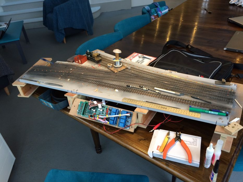 |
||
|
posted: 20 Feb 2017 22:03 from: Andrew Duncan
click the date to link to this post click member name to view archived images |
And this one is from Chrome but about 2MB in size. This shows the track and rodding sprayed and I'm almost ready for ballasting. But before I do that I must test it out electrically with a loco. Problem is all my locos bar a mongrel 43xx Mogul are still in 16.5mm gauge from my original Maiden Newton / Yeovil layout in 00. And that one loco doesn't have pick ups fitted let alone a chip fitted. It is just visible in this photo bottom left, but looks a bit sorry for itself sitting there tenderless....2787_201643_530000000.jpg 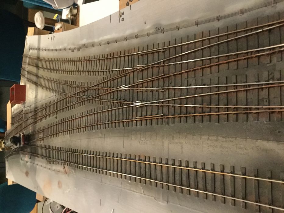 |
||
|
posted: 1 May 2017 22:34 from: Andrew Duncan
click the date to link to this post click member name to view archived images |
Hello everyone Uploading these photos almost drove me round the bend tonight. Try as I might I couldn't get the captions to work or get the pictures to load in anything other then haphazard order.....!!!! So anyway here's a bit more progress with the MPD. I'm using a London Road Models turntable 50' (although it should only be 44') which is turning into a very nice model and its driven by a Chatham models turntable drive which, so far has proved a relatively easy install once I'd got the wiring the correct way round! The track that I built 3 years ago went down surprisingly easily although I've not rested it yet under power. Like the junction I'll be using Megapoints controller and servos to switch the turnouts. Handily there are four spare ways on the junction board that will deal with them. This time though I'm going to use conventional micro switches to change the polarity of the crossings. I hope the chronology is reasonably clear. Andrew 2787_011703_150000000.jpg 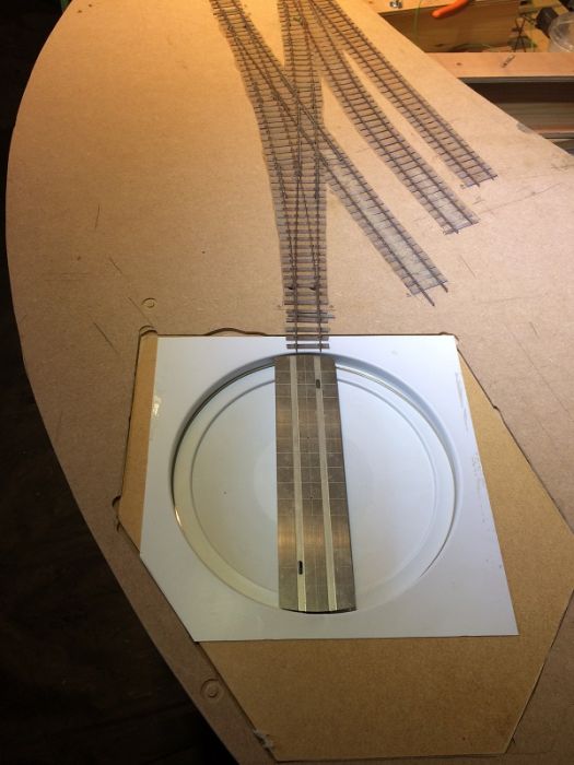 2787_271836_510000000.jpg 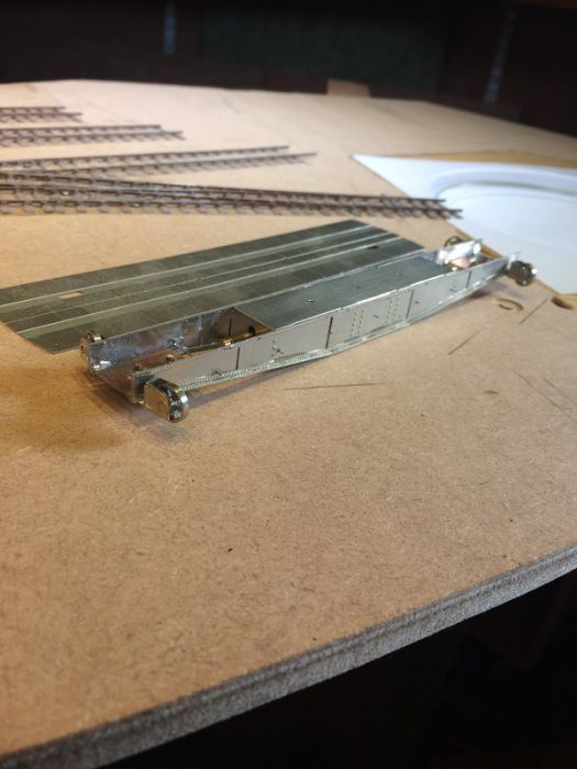 2787_011708_360000000.jpg 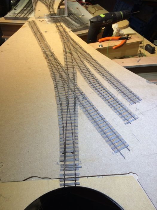 2787_011707_580000000.jpg 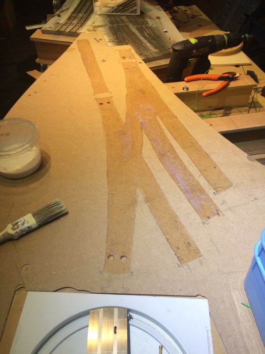 2787_011706_450000000.jpg 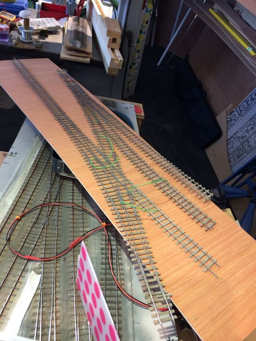 2787_011650_330000000.jpg 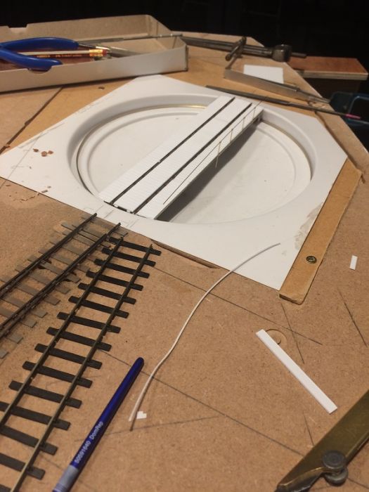 |
||
|
posted: 6 May 2017 20:45 from: Andrew Duncan
click the date to link to this post click member name to view archived images |
Hello everyone A bit more progress on the turntable. The top photo shows a Mainline Mogul with the cab and fire box cut off and a spare Mitchell cab and firebox substituted. When its finished I hope itll be difficult to tell it from a real Mitchell Mogul? Anyway its sitting the almost finished Turntable bridge, just the far handrail stanchions to add and we'll almost be there. The lower photo shows the gound work progress around the turntable area along with the well stone wall. Andrew 2787_061530_360000000.jpg 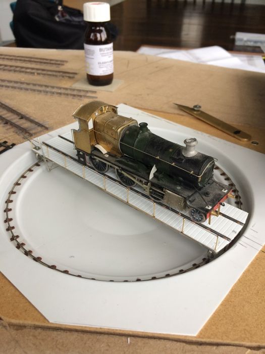 2787_061532_180000000.jpg 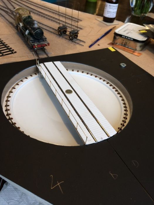 |
||
| Last edited on 11 May 2017 21:00 by Andrew Duncan |
|||
|
posted: 9 May 2017 09:22 from: ScottW
click the date to link to this post click member name to view archived images |
Lovely work, Andrew, very inspiring. Looking forward to the next update. Scott |
||
|
posted: 11 May 2017 20:58 from: Andrew Duncan
click the date to link to this post click member name to view archived images |
Hello Scott Thanks very much for your kind comment. I'll post more as I progress! Kind regards Andrew |
||
|
posted: 24 May 2017 17:37 from: Michael Henfrey
click the date to link to this post click member name to view archived images |
Very impressive. Can I ask, What did you use to get the colours of the sleepers and chairs looking like that in the 6th post down. It looks about spot on for what I am aiming for. Cheers |
||
| Last edited on 24 May 2017 17:40 by Michael Henfrey |
|||
|
posted: 28 May 2017 00:00 from: Andrew Duncan
click the date to link to this post click member name to view archived images |
Michael Henfrey wrote: Very impressive. Can I ask, What did you use to get the colours of the sleepers and chairs looking like that in the 6th post down. It looks about spot on for what I am aiming for.Hello Michael Thanks for your comments. It's been over two years since I built this track but from memory having built it, whilst still attached to the paper template I fist sprayed it with grey primer which sticks well to wood and metal and provides a good neutral lightship background for further colouring. I then took it out into the garden and gently attacked it with my airbrush using a mid grey brown for sleepering and a darkiskish rust colour for the rail sides. It now needs further colouring with dry brushing and powders or ground pastels to give it some variation in colour and, as this is an MPD then a bit more grime and filth. I think that when in doubt keep it light in colour and under state. Kind regards Andrew |
||
|
posted: 6 Jul 2017 21:39 from: Andrew Duncan
click the date to link to this post click member name to view archived images |
Hello everyone At the end of the month I'm treating myself to a Missenden Abbey summer retreat so hope to be reporting some decent progress on my return, fingers crossed! Kind regards Andrew |
||
|
posted: 10 Aug 2017 22:07 from: Andrew Duncan
click the date to link to this post click member name to view archived images |
Hello Everyone Well I'm back from a great week at Missenden Abbey. Did I achieve my aim of making some significant progress? Well yes I did although I must admit it doesn't look that impressive, but on the other hand building point work with C&L components is not a quick process and my hopes that I might return with a baseboard largely complete evaporated in the first few days there! On the other hand Tony Gee (one of the tutors) showed me how he build the crossings with a simple set of gauges, that allowed me to make my first really reliable crossing (the bit I always find the hardest to do consistently where the wing rails and knuckles line up with point of the V) and that was probably the biggest single move forward for me. Add to that seeing how other modellers do things or just store their tools and materials is an education in itself. So thanks go to Tim, Barry, Pat (who allowed me to borrow and ruin his cutting mat), David, Mark, Chris who organises the whole thing and Simon( who I think follows this thread) for all your help support and kind comments. Edit. I realise i missed out Mick Bonwick who provided the spray booths and who could do quite astonishing things with an airbrush! Below are a couple of photos of progress to date on that board. 2787_101646_050000000.jpg 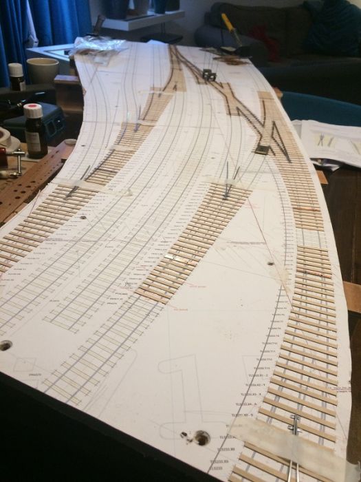 Here is view looking south towards the platforms with the up and down main line running either side of the carriage siding in the centre of the picture and on the left a row of three turnouts giving on to the marshalling yard area directly opposite the platforms. 2787_101652_300000000.jpg 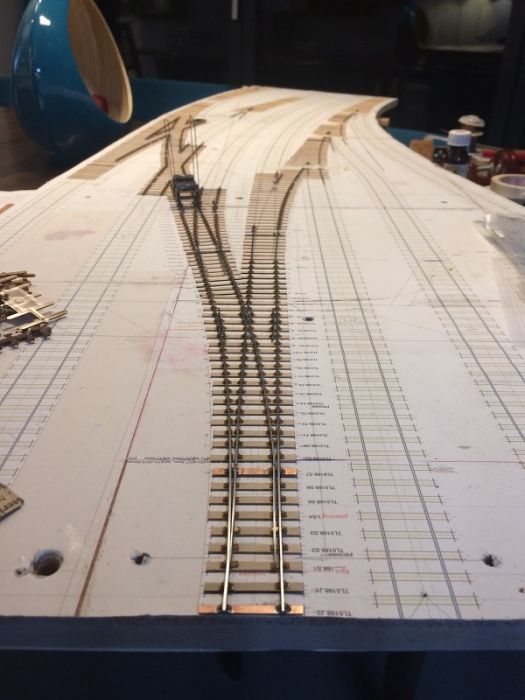 and here's a view in the opposite direction with the platform (when its built) immediately on the left of the turnout and my "dodgy trackwork detector wagon" about half way down the board. This is a lovely example of how Templot enables beautiful curved trackwork to be built in a way that I would never achieve left to my own devices. Great program Martin, thank you. Kind regards, Andrew |
||
| Last edited on 5 Sep 2017 22:38 by Andrew Duncan |
|||
|
posted: 5 Sep 2017 22:30 from: Andrew Duncan
click the date to link to this post click member name to view archived images |
Hello everyone A bit more progress here on the base board above. I'm now working on the last three turnouts on this baseboard.of the layout. 2787_051722_450000000.jpg 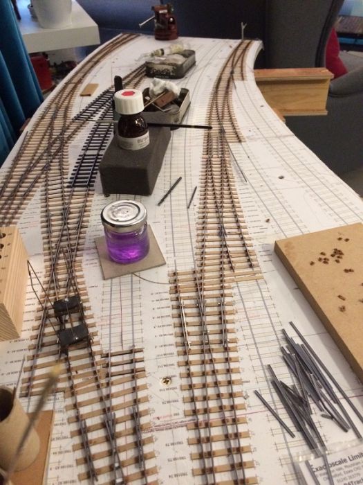 When I was at Missenden Abbey earlier last month both Tony Gee and Mark Tatlow suggested a very similar "hidden tie bar arrangement" which as these three turnouts are near the front of the layout I thought I may try out.I'll let you know how i get on. Andrew |
||
| Last edited on 5 Sep 2017 22:31 by Andrew Duncan |
|||
|
posted: 13 Sep 2017 11:48 from: Richard_Jones
click the date to link to this post click member name to view archived images |
Hello Andrew, Once again, very impressed by your progress I had a quick look back through your thread and don't think I have missed it, but could you provide any more details of your "sub-baseboard" (my terminology) that allows you to work on "manageable" piece of trackwork, and how that integrates/assembles into the overall layout (or point to where I missed it! many thanks Richard |
||
| Last edited on 13 Sep 2017 12:24 by Richard_Jones |
|||
|
posted: 13 Sep 2017 19:59 from: Andrew Duncan
click the date to link to this post click member name to view archived images |
Richard I'm sorry to hear that you're not making the progress that you'd have liked but when you last updated Singleton you'd been drawn down the 7mm path which I'm sure is a fascinating alternative to 4mm, it would be great to see any progress there? I popped down the garden earlier to take a couple pictures that may at least partially answer your question. The layout is hung off Spur shelving brackets screwed to the walls, so that there are no legs to get in the way and take up precious space in my shed. The brackets support a bed of 18mm ply cut approximately 2' (600mm) deep (from back to front ) that goes all around the perimeter of the shed with a lifting flap at the door. On top of this shelf the various layout baseboards (between 3'6" & 5'0" long ) sit approximately 3.5" (90mm) above that surface supported on 3" X 1" batten topped and tailed with strips of 12mm ply about 3" wide. The ply tops to these supports also provide the method of joining the various baseboards together. I'll take a photo of that later, if I can, to make it clearer. Now nearly every time I load pictures something goes awry so I'll keep my fingers crossed that I don't lose the lot so may do this in two or more posts. Kind regards Andrew 2787_131455_260000000.jpg 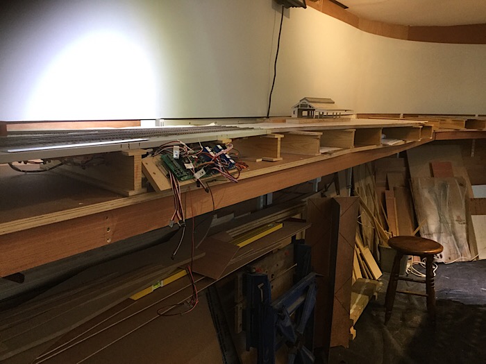 2787_131457_520000000.jpg 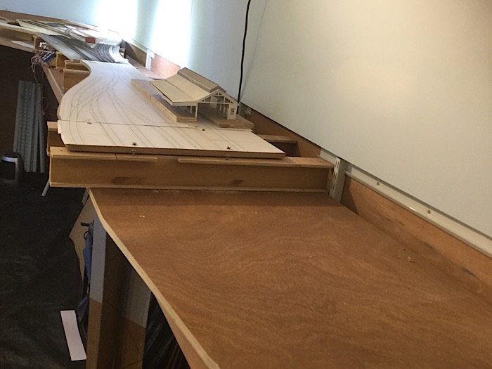 |
||
| Attachment: attach_2492_2547_IMG_0077.JPG 313 | |||
|
posted: 13 Sep 2017 20:15 from: Andrew Duncan
click the date to link to this post click member name to view archived images |
Richard Just to finish off this post, you know I think the reason I've been able to make the progress that I have, is a lot to do with this type of construction. It enables me to be sat in the main family room where we live most of the time pottering around with stuff whilst still be relatively sociable. I don't have to disappear off into the loft or cellar or shed! Anyway here's another picture. If I'm still unclear please do ask. Andrew2787_131513_550000000.jpg 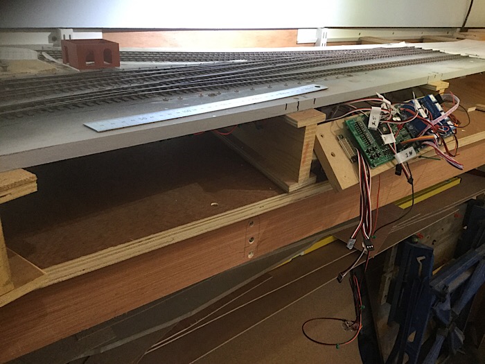 |
||
|
posted: 13 Sep 2017 22:23 from: Andrew Duncan
click the date to link to this post click member name to view archived images |
PS I realise that looking at these pictures that you might be wondering what happens at the front of the layout? I'm intending to use a sort of Iain Rice / Barry Norman / Flintfields type of jigsaw scenery which will plug into the 90mm gap between the 18mm ply shelf and the underside of the baseboards themselves. Andrew |
||
|
posted: 13 Sep 2017 22:47 from: Richard_Jones
click the date to link to this post click member name to view archived images |
Hi Andrew, many thanks for your informative and interesting reply - its a very nice concept, but as Singleton won't have a permanent home, I will have to fall back on single self supporting baseboards, but keeping them to a manageable size so that I can work on one (or two) at a time in the kitchen/utility room. As (lack of) progress is again about to be impacted by a 3 month trip to the Southern Hemisphere, visiting family, I wondering if I can get one or two vehicles and tools in my luggage to work on whilst I am away - many years ago I took my portable workshop (by plane) to the North of Scotland and although it raised a few eyebrows at security, it was allowed through - not so these days! best wishes Richard |
||
|
posted: 13 Sep 2017 23:24 from: Andrew Duncan
click the date to link to this post click member name to view archived images |
Hello RichardI hope you have an enjoyable time down south and perhaps get in some gentle modelmaking as well. Bon vacances. Andrew |
||
|
posted: 20 Sep 2017 23:53 from: Andrew Duncan
click the date to link to this post click member name to view archived images |
Hello everyone Here's a picture or two of tonight's progress. I'm starting to install the servos for the turnouts. Somewhere on the Scalefour E forum I found a link to the company Alu Rail Tech who produce these rather knatty little right angle brackets for holding not only the servo but also one or two microswitches. On the underside of the baseboard I've stuck a mirror image print out of the track so that I don't get confused when wiring up. This I omitted to do with the junction board producing some unexpected results. Andrew 2787_201839_300000000.jpg 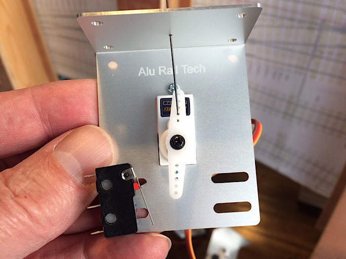 2787_201838_360000000.jpg 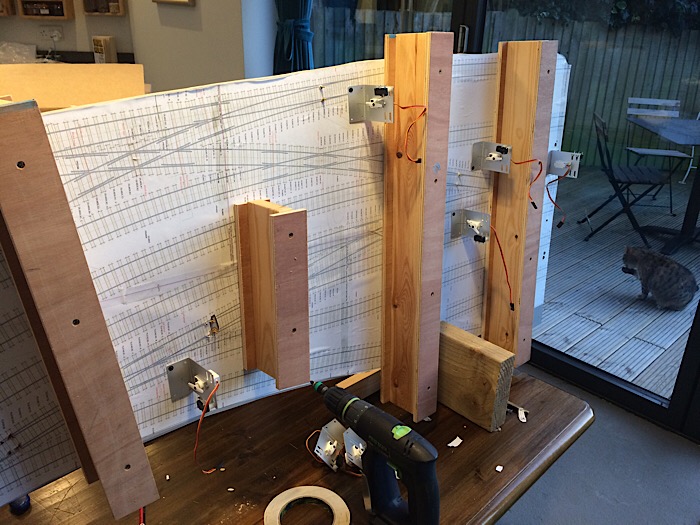 2787_201843_250000000.jpg 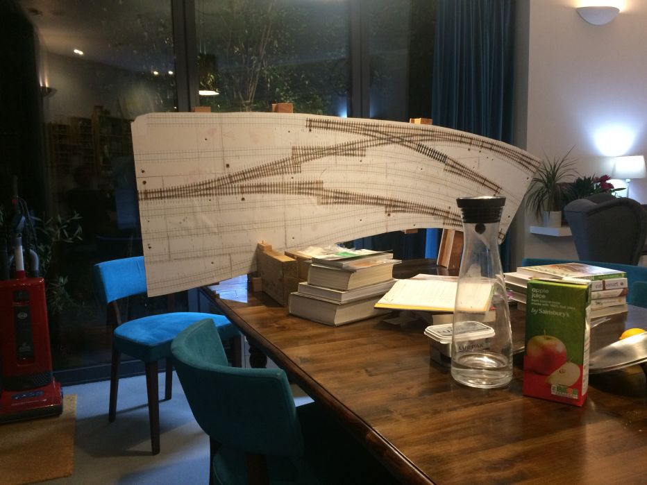 Here's the other side standing on the end of the kitchen table this evening looking almost Picasso-esq.... EDIT Minor point probably but I think I meant Dali-esq! Apologies to both. |
||
| Last edited on 21 Sep 2017 07:26 by Andrew Duncan |
|||
|
posted: 1 Oct 2017 19:23 from: Andrew Duncan
click the date to link to this post click member name to view archived images |
Hello A minor update on progress. The photo below shows he baseboard I've been working on temporarily in place to check clearances and all seems ok! 2787_011413_460000000.jpg 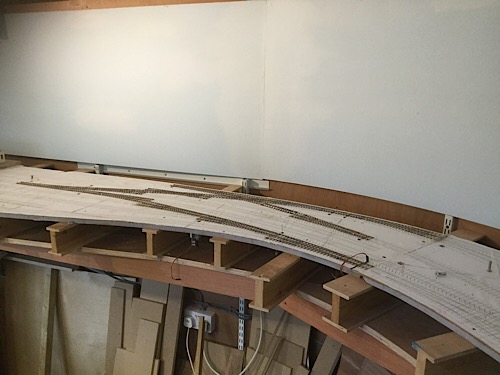 The next photo shows the start of the megapoints installation for both turnouts and signals. 2787_011421_560000000.jpg 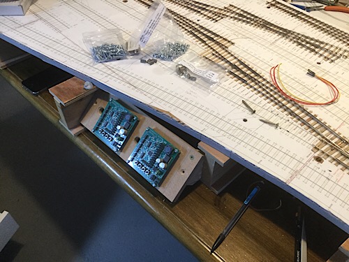 That's it for now. Kind regards Andrew |
||
|
posted: 19 Oct 2017 23:18 from: Andrew Duncan
click the date to link to this post click member name to view archived images |
A brief update of my progress in the last few weeks and a request for help. I’ve completed the basic wiring for the servos to the Megapoints control boards, there are two on this baseboard because I’ve got 11 turnouts and five or six signals including three working(I hope) ground signals which are easily visible ( I’m not going to the trouble of making a tiny disc rotate a couple of millimetres if I can easily see it. 80/20 rule). A very welcome upgrade that Dave Fenton has done to the latest Megapoint control boards is that the servos no longer chatter to each other which is a blessed relief and what’s more for a modest sum you send back your old boards to be up graded. My two old ones will be going back for that upgrade just soon as I can summon up the energy to unplug them and put them in the post. The question I have is has anyone got any good ideas on logging wiring and how to keep a track of it all? At present I’m labelling each end of the servo wires going back to the boards with the turnout number and the track feeds are colour coded red and black. The crossing feeds to the micro switches are white. In addition I’ve printed out Templot plans of each baseboard at 20% of full size on A3 paper and have plotted the exact positions of all feeds along with turnout numbering, but still feel that I’m not doing enough to make fault finding later, as easy as I can? Here’s a photo of the underside 2787_191809_330000000.jpg 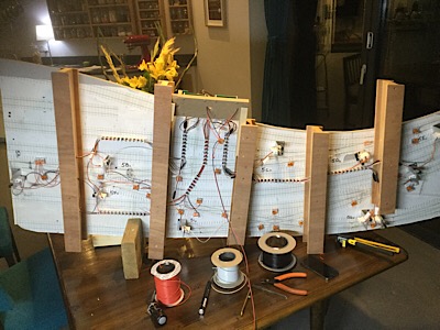 Kind regards Andrew |
||
|
posted: 20 Oct 2017 06:27 from: Andrew Barrowman
click the date to link to this post click member name to view archived images |
Hi Andrew, It all looks very nice! Regarding the wiring identification you might try attaching labels from a P-touch or similar. Just use a unique three or four digit identifier at each end. I prefer to keep the wiring a bit loose (and not very tidy) so that I can tug on a wire to find where it terminates. There's another reason for doing it that way. Bundling the wires into a nice neat cable harness tends to increase the cross-talk between electrical signals. Usually that's not a problem for typical model railway conductors, but servos have really lousy noise-immunity and it's not difficult to couple enough energy into their inputs to trigger a cycle. It's quite likely that is one source of the chattering you have observed. Regards, Andrew |
||
|
posted: 20 Oct 2017 12:38 from: Phil O
click the date to link to this post click member name to view archived images |
I agree with Andrew, keep all servo cabling well away from traction cabling, if they have to get close too each other wrap them in foil as this helps to shield them from each other. Phil |
||
|
posted: 20 Oct 2017 12:47 from: John Shelley
click the date to link to this post click member name to view archived images |
Phil O wrote: I agree with Andrew, keep all servo cabling well away from traction cabling, if they have to get close too each other wrap them in foil as this helps to shield them from each other.Or use a screened wire, easier than trying to wrap foil around. Earth the screen, or foil, of course. John |
||
|
posted: 20 Oct 2017 15:06 from: Phil O
click the date to link to this post click member name to view archived images |
John Shelley wrote: Phil O wrote:JohnI agree with Andrew, keep all servo cabling well away from traction cabling, if they have to get close too each other wrap them in foil as this helps to shield them from each other.Or use a screened wire, easier than trying to wrap foil around. Earth the screen, or foil, of course. I wrap the foil around the whole bunch of cables, not each individually. I only had to do it once where there was a conflict of the two cable runs, overal about 9inches or so on each run was enough to stop the twitch. Phil |
||
|
posted: 20 Oct 2017 15:18 from: John Shelley
click the date to link to this post click member name to view archived images |
Phil O wrote: JohnDid you connect the foil to earth or just leave it disconnected? John |
||
|
posted: 20 Oct 2017 19:03 from: Andrew Barrowman
click the date to link to this post click member name to view archived images |
I have not found shielding to be very effective. I think that's because the interference is mainly induced (bit like a transformer). If you do run into horrible problems with servos, all is not lost. You can "front-end" the input with an opto-isolator and that makes them pretty immune to interference. I don't want to turn Andrew's thread into a discussion about servos. PM me if you need more info. Regards, Andrew B |
||
|
posted: 20 Oct 2017 19:11 from: Martin Wynne
click the date to link to this post click member name to view archived images |
Andrew Barrowman wrote: I don't want to turn Andrew's thread into a discussion about servos.Nor me. But I would simply add a pull-up resistor at the servo end. What is the sink/source capacity of the driver? regards, Martin. |
||
|
posted: 20 Oct 2017 21:14 from: Andrew Barrowman
click the date to link to this post click member name to view archived images |
Martin Wynne wrote: But I would simply add a pull-up resistor at the servo end. What is the sink/source capacity of the driver?Hi Martin, You could certainly give that a shot, but if I understand correctly what's going on here, that might actually make the problem worse I'm referring to the cheapest analog servos (SG90 type). When the input goes positive it fires a monostable and that starts a servo positioning cycle. The width of the input pulse provides the desired position information. There's not too much data available on the chip inside the servo but from what I've seen the input goes straight into the base of a NPN transistor. If the input signal rises to around 0.7 volts, the transistor turns on and triggers the monostable cycle. Rather than increasing the noise margin a pull-up resistor can actually reduce it. One solution that does seem to help is to elevate the servo's 0 volt rail above the 0 volt rail of the controller. That can be done with a diode, a resistor and a capacitor. The voltage drop through the diode raises the the servo's 0 volt rail by around 0.7 volts and that does add quite a bit of noise margin. Unfortunately it also violates the servo's spec (such as it is), but in practice it doesn't seem to cause a problem. Oh dear! Maybe we should start a new thread on servos Regards, Andrew B |
||
|
posted: 23 Oct 2017 22:48 from: Andrew Duncan
click the date to link to this post click member name to view archived images |
Gentlemen Thank you for your varied if slightly worrying thoughts about the servos picking interference. My hope is that as the leads to the servos are all pretty short (the longest lead is about 2' 6" long and the Megapoints boards are mounted on the baseboards for that reason) that they wont pick up anything significant in the way of interference and all will be well. However I thought the tip about screening with foil was a useful one that also seems easily doable if push comes to shove. Indeed when I referred to the servos "chattering" on the old version board it was I believe, not because of interference, but because the power was constantly on in that version. If I understood Dave correctly, the new version of the software now turns off after a moment of moving the servo, hence chatter no longer, just silence. Until the system is tested with the full force of my ZTC 5amp powered 511 I suppose I'm not really going to know the score. It occurs to me that perhaps I should get some trackwork finished and test it before going too much further. Perhaps I'll also drop Dave Fenton an email to get his take on it as well? Many thanks for all your various thoughts on the subject. Kind regards Andrew PS if you have any further thoughts on logging wiring in a meaningful way that makes problem solving easier down the line, I'd be interested to hear your thoughts. |
||
|
posted: 23 Oct 2017 23:27 from: Tony W
click the date to link to this post click member name to view archived images |
Andrew Duncan wrote: The question I have is has anyone got any good ideas on logging wiring and how to keep a track of it all? At present I’m labelling each end of the servo wires going back to the boards with the turnout number and the track feeds are colour coded red and black. The crossing feeds to the micro switches are white.Hi Andrew. That all looks quite neat and tidy. Documenting your layout wiring is often overlooked but certainly essential for anything more than a shunting plank, but can seem a pretty thankless task. A combination of circuit drawings and wiring lists is a good starting point. My preferred wiring method relies on soldered tag strips which can be numbered. A list of connections between tags, the colour of the wires and the function of each wire helps fault tracing. Colour coding is also very helpful as you are doing. Standardisation of repeating circuits is a good idea. Make a record of the wiring through connectors between baseboards pin to tag strip each side. The wiring record for my layout Green Street eventually had to be kept in a lever arch file as there was so much of it, but then the wiring for it did become somewhat complicated by the design spec. Indeed much of the documentation for the wiring was done before the actual layout wiring was commenced and I still ran out of spare solder tags on occasion as new functions were added in the light of experience. Regards Tony. |
||
|
posted: 24 Oct 2017 14:53 from: Andrew Duncan
click the date to link to this post click member name to view archived images |
Hello Tony Thanks very much for your thoughts and experience which I think maybe just what I'm looking for. I've a couple of questions for you which I've put in your text below... Tony W wrote: Hi Andrew. My preferred wiring method relies on soldered tag strips which can be numbered. A list of connections between tags, the colour of the wires and the function of each wire helps fault tracing. Colour coding is also very helpful as you are doing. Standardisation of repeating circuits is a good idea. What do you mean by repeating circuits? Make a record of the wiring through connectors between baseboards pin to tag strip each side. Do you have a copy of what you've done that you might be able to show me, a photograph or scan of one of the pages perhaps?You maybe regretting having answered my questions so fully now, but any help that you can give me would be most appreciated. Kind regards Andrew |
||
| Last edited on 24 Oct 2017 19:16 by Andrew Duncan |
|||
|
posted: 25 Oct 2017 17:25 from: Tony W
click the date to link to this post click member name to view archived images |
Andrew Duncan wrote: Hello TonyHi Andrew. Basically yes. A circuit drawing or diagram can cover any number of scenarios, from the trackwork with section power feeds, crossing feeds, isolating gaps, section breaks (although if using DCC you may not have any), to the control boards for said layout. A wiring list is simply a list of connections between tags, the colour of the wires and the function of each wire. Repeating circuits. If a circuit is duplicated several times, it makes sense to use the same colour wires and physical layout each time within that circuit although not necessarily for the control wire to it. That commonality means you will be more familiar with individual circuits that go to make up the whole. I will scan some examples for you. Most of the originals are in .doc format for ease of editing as changes are made. Regards Tony. |
||
|
posted: 25 Oct 2017 22:52 from: Andrew Duncan
click the date to link to this post click member name to view archived images |
Thanks very much Tony. I’ll look forward to seeing some examples as well when you have a moment. Kind regards Andrew |
||
|
posted: 2 Nov 2017 01:01 from: Tony W
click the date to link to this post click member name to view archived images |
Hi Andrew. Well that has proved a useful exercise. On visiting some of the files I wished to send you as examples of how I did things, I discovered that they either needed correcting or were in the process of being updated but had not been completed, so has spurred me on to do so. Rather than post them as pictures, I think it better to add them as attachments as some of the text will be too small to read otherwise. This will take three postings. The first file is the Track plan wiring schematic for Green Street and may take a bit of studying. Board 1 is to the left of the vertical dotted line, then board 2 to 4. The tracks are numbered from the bottom upwards. |
||
| Attachment: attach_2553_2547_Track_plan_electrics.GIF 346 | |||
|
posted: 2 Nov 2017 01:04 from: Tony W
click the date to link to this post click member name to view archived images |
The second file is for the connecting cable between boards 1 and 2 and are I hope largely self explanatory. |
||
| Attachment: attach_2554_2547_Wiring_list_1.GIF 315 | |||
|
posted: 2 Nov 2017 01:12 from: Tony W
click the date to link to this post click member name to view archived images |
The third file may be of some use if you have a Three throw turnout to deal with. As the blades overlap, it is important that the two point motors throw sequentially to avoid stressing the drive mechanisms. I have used Fulgurex point motors modified with 10 way connectors and ribbon cable jumpers to allow easy disconnection if required. A major consideration with an exhibition layout. I am sure you will have further questions once you have studied these. Regards Tony. |
||
| Attachment: attach_2555_2547_Three_throw_turnout.GIF 1033 | |||
|
posted: 2 Nov 2017 10:18 from: JFS
click the date to link to this post click member name to view archived images |
Tony W wrote: Hi Tony, Very interesting! But a bit of clarification needed - sorry if you have given this elsewhere and I have missed it. What are the lines A,B,C and D? Also the Ind and Ex designation - which I might be able to guess! The diagram looks as if each of the switches 1 - 12 are just three pole, but if it were that simple, then as-drawn, throwing any one of them shorts a,b,c together - which cannot be the case - in which case, what are each of the three "poles" for, and what stops them being operated together? Best wishes, Howard |
||
|
posted: 2 Nov 2017 12:37 from: Tony W
click the date to link to this post click member name to view archived images |
JFS wrote: Tony W wrote:Hi Howard.Hi Tony, That is the problem of publishing one page of a manual intended for personal use out of context. I suspected that further explanation would be required. A,B,C,D are the four controller buses nominally available to switch to a track section. Ind is short for Industrial and is the power station empire. If you have operated the layout you will know what I mean by that. Controller D is permanently connected to this. Ex is short for extra and is unused at present. The three switch poles on section feeds 1 - 12 are individual relay contacts. The long term plan was for micro processor control of the signal box interlocking and power feeds to sections 1 to 12 will be selected using 2 bit binary control, hence only one relay contact can be made at a time with "00" being off. At present, as a temporary measure and we all know about those, only controllers A and B are available via centre off toggle switches, in effect manual Cab control. You are correct about the shorting issue, it is not uncommon for an operator to forget to restore a section feed switch when they have finished with it and then set up another route using another controller. If the loco overruns the section gap between the two controllers, a short occurs and Pentrollers don't like it up em as we discovered the hard way long ago. Hope this answers your questions. Regards Tony. Edit: Perhaps the attached file may help. |
||
| Attachment: attach_2556_2547_Section_feeds_and_isolators.gif 993 | |||
| Last edited on 2 Nov 2017 16:54 by Tony W |
|||
|
posted: 2 Nov 2017 17:41 from: JFS
click the date to link to this post click member name to view archived images |
Many thanks Tony - I guessed correctly with "ind" - but incorrectly with "Ex"!! Best wishes, |
||
|
posted: 3 Nov 2017 22:51 from: Andrew Duncan
click the date to link to this post click member name to view archived images |
Hello Tony Thanks very much for downloading these for me. I'll take a closer look over the weekend and see what I do and do not understand and come back to you with any questions if I may? Kind regards Andrew |
||
|
posted: 3 Nov 2017 23:40 from: Tony W
click the date to link to this post click member name to view archived images |
Hi Andrew. I thought it had all gone quiet! By all means. Regards Tony. |
||
|
posted: 4 Nov 2017 17:19 from: Richie Kynaston click the date to link to this post click member name to view archived images |
Very impressed with the trackwork construction. If i can achieve anything halfway as good in 7mm, i'll be happy! Keep up with the updates. Rich |
||
|
posted: 5 Nov 2017 22:18 from: Andrew Duncan
click the date to link to this post click member name to view archived images |
Hello Tony Thanks for uploading the second wiring diagram it does help to get a better sense of the layout. I've not got very far so far this weekend but have managed to scan my current record of baseboard no 5 (a print out of the current section of the layout printed at 20% sizing Edit COPY ATTACHED) of turnouts numbered and all wiring points logged on it. The position of the droppers are marked, usually in pairs, at the point they are soldered to the rail, as I've often found in the past that I've forgotten where the feeds are, which can be very frustrating! I've numbered the turnouts all starting 5 as the baseboard is number 5. They begin 5A, 5B etc and work there way through to 5K. I don't, as you observed have the need for isolating sections as this is DCC, so my next job is, I think, to number the feed wires which I have already pencilled in. Again here I've used the board number to dictate the first numeral but I'm beginning to think this is over kill and I'll probably just re-number them 1-50 or so...? Then make a list of the wires and their function as you have on a separate Word document. Any thoughts you have would be gratefully accepted. Thanks again for your support and ideas. Kind regards Andrew Edit: I've just noticed that the scan ive uploaded has cut a few inches off the left hand end of the baseboard chopping the first turnout in half! |
||
| Attachment: attach_2564_2547_Yeovil_North_Board_5_-TO_Numbering_-_200_DPI.pdf 349 | |||
| Last edited on 5 Nov 2017 22:38 by Andrew Duncan |
|||
|
posted: 5 Nov 2017 22:29 from: Andrew Duncan
click the date to link to this post click member name to view archived images |
Richie Kynaston wrote: Very impressed with the trackwork construction. If i can achieve anything halfway as good in 7mm, i'll be happy! Keep up with the updates.Hello RichThank you for your kind words and encouragement. Its always good to hear !! Kind regards Andrew |
||
|
posted: 5 Nov 2017 23:35 from: Tony W
click the date to link to this post click member name to view archived images |
Hi Andrew. Have you considered numbering the points as they are / would have been in the signal box diagram as this will save cross referencing later on. The signals will also have to be added to the scheme as well. This is the system I used on my layout, fictitious though it is. The points with an M prefix are those that would have been manually operated with hand levers had it existed. There is no right or wrong way to do it, but at the end of the day you need to have something that works for you and that you can understand. Also give some thought to being able to break down the DCC fed areas into smaller sections, i.e. using plugs and sockets to enable faults to be isolated more easily. As it happens I do have a passing interest in Yeovil Pen Mill as a good friend of mine always wanted to model it in P4 but sadly never got the chance, so it is nice to see it taking shape in your capable hands. Regards Tony. |
||
| Last edited on 5 Nov 2017 23:38 by Tony W |
|||
|
posted: 6 Nov 2017 22:28 from: Andrew Duncan
click the date to link to this post click member name to view archived images |
Hello Tony Thanks very much for the idea of using the signal box diagram. Deceptively simple ideas are often the inspired ones, and your idea seems to come very much in that category. You're right of course about the signals which aren't on that plan but need to be included and although I've allowed for them electronically I've not yet given them sufficient thought physically in either location or construction method. As a result of a comment of Howard Bolton's that I came across the other day I've been following Steve Hewitt's authoritative thread in RM Web on signal construction which is both fascinating and instructive. Now your thoughts on fault finding have set me thinking as to whether I've got enough places to "break" wires for fault finding. That'll require a bit more thinking I think, so for the moment I'll conclude by thanking you for your comments on on your connection with Yeovil and the compliment of it being "in safe hands". I was really quite touched by your words. Kind regards Andrew |
||
|
posted: 7 Nov 2017 22:37 from: Tony W
click the date to link to this post click member name to view archived images |
Hi Andrew. One other thing. You may have noticed that the track diagram was marked issue 9. When you modify the layout, make sure you update the documentation to match. There is nothing worse than trying to fault find with out of date reference material. Guess how I know. Regards Tony. |
||
|
posted: 8 Nov 2017 13:18 from: Andrew Duncan
click the date to link to this post click member name to view archived images |
Hmm wise words Tony but that’s going to require self discipline...! When you say version 9 where they track plan changes or something elsethat you’d changed?Andrew |
||
|
posted: 8 Nov 2017 22:21 from: Tony W
click the date to link to this post click member name to view archived images |
Andrew Duncan wrote: When you say version 9 where they track plan changes or something else that you’d changed?AndrewHi Andrew. A mixture of things really. The layout was extended once with the addition of an off scene industrial siding, which required the replacement of a turnout with an outside slip, but mostly it was down to errors and amendments made over the course of time. The most recent change (from issue 8 to 9) was replacing the pencil drawn original with the computer graphic I posted, but I took the opportunity to update one of the point motor numbers from M2 to M2a for clarity. This change had been noted in red ink on the earlier working copy some years ago, so no, I don't exactly rush to do the updates, just make a note of them at the time. Regards Tony. |
||
|
posted: 15 Jan 2018 19:43 from: Andrew Duncan
click the date to link to this post click member name to view archived images |
Hello TonyI thought I’d replied to your response above but apparently not so my apologies for the lack of acknowledgment and thanks for the explanations! Kind regards and a happy new year. Andrew |
||
|
posted: 15 Jan 2018 22:53 from: Andrew Duncan
click the date to link to this post click member name to view archived images |
I’m in retail and quite apart from the challenges that that brings Christmas is our busy time so unfortunately gets in the way of model railways. So progress has been a bit slow of late. I have however now started add the plain track that connects all the point work on this base board, very roughly cutting it slightly long for its location and jus placing it down to be able to attach the droppers in place. My plan then is to spay track colour on both the plain track and point work, lift the plain track and then commence balasting of the turnouts. Then replace the plain track in a bed of PVA and ballast at the same time. My fear is that the two different methods of balasting may look different but I shall have to cross that bridge if and when the happens. A couple pictures to follow Andrew |
||
|
posted: 16 Jan 2018 23:51 from: Andrew Duncan
click the date to link to this post click member name to view archived images |
And here they are. I’ve also just realised that I’ve yet to build the catch point to protect the down main from carriages wandering out of their siding between the up and down main lines. A friend pointed out its absence a couple of months ago and sure enough when we checked the photos there it was... 2787_161841_420000000.jpg 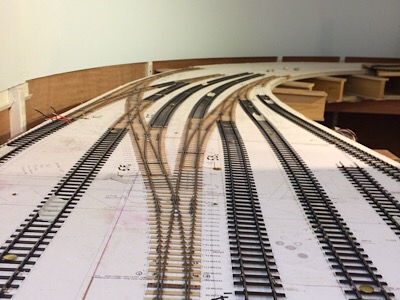 2787_161844_160000000.jpg 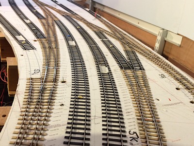 So little more trackwork before spraying and ballasting and I need to install the dummy point rodding as well. Andrew |
||
|
posted: 14 Jul 2018 05:11 from: Andrew Duncan
click the date to link to this post click member name to view archived images |
I can barely believe that its been 6 months since I’ve reported any progress on Pen Mill. I’ve not been totally idle, nor have I made great leaps forward. The catch point is in on the carriage siding. I’ve added all the feeds/ droppers in now, so the amount of wires underneath have burgeoned. I’ve almost got all microswitches switching the correct polarity. I’ve even got close to getting the diamond crossings being switched by their adjacent turnouts. It remains to be seen whether the micrswitches stay correctly aligned to give reliable switching over time. I maybe worrying unnecessarily but I’m beginning to wonder whether I’d have been better off either using either Megapoint electronic control ( as I did on the junction baseboard)or frog juicers for this? Does anyone have any experience of the Gaugemaster frog juicer. I have bought a couple but not used them yet and since read that they will only take a couple of amps ( my ZTC has a 5 amp output) power going through them? The other problem of the microswitces is that they are bulky and despite the elegance of the Alu Rail brackets, being under the baseboard, am I asking for trouble having a system that can go out of adjustment and needs baseboard removal to get at them? In retrospect I think I may regret the microswitch and end up replacing them in part or completely with electronic control. Hers a photo of the current state of progress of the underside so you can see a bit of what I mean. 2787_132336_080000000.jpg 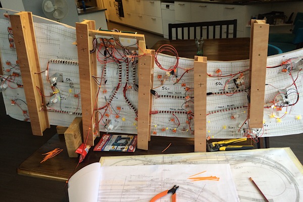 Looking at this now I’m so glad I stuck (a mirror image) a copy of the plan to the underside, as I’ve found my ability to remember what I’ve just look at topside and retain that a few moments later when looking at the underside is very limited. So the plan stuck underneath is a godsend. And whilst talking of that and taking some advice from a number of you and Tony in particular, on record keeping, I’ve attached a picture of my wiring records which I’m reasonably pleased with. 2787_132348_590000000.jpg 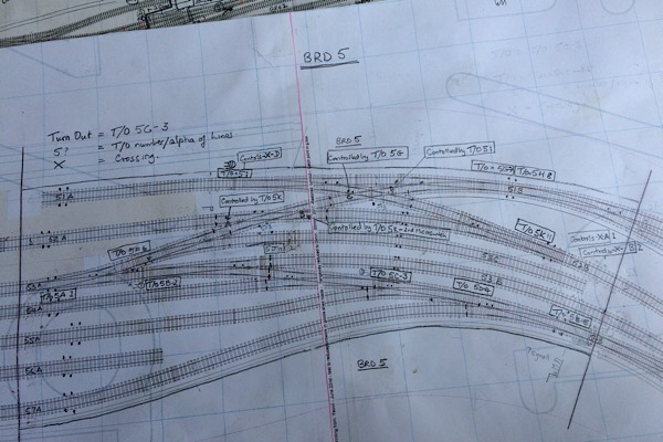 It’s not very clear but it shows exactly where each pair of droppers are, turnout numbering and what turnouts control the 4 diamond crossings. There’s a legend,top left, that reminds me what my abbreviations mean! So now it’s July and in two weeks or so I’m off to Missenden again so there at least I’ll be able to get something done largely without interruption I hope. Kind regards Andrew |
||
|
posted: 14 Jul 2018 19:46 from: Tony W
click the date to link to this post click member name to view archived images |
Hi Andrew. It crossed my mind only a couple of days ago that you had not posted anything for while, so it is good to see that you are still making progress. Regards Tony. |
||
|
posted: 15 Jul 2018 00:37 from: Andrew Duncan
click the date to link to this post click member name to view archived images |
Thanks Tony and yes it is good to be back “at it” again. I’m hoping to be able to make some good progress in the next few weeks. Having said that I find building the point rodding a bit of a slog and I’m not attempting to make mine work! The other thing that’s occupying me is the ballasting. From photos it appears to be largely ash and cinders with a little stone ballast between the rails in places. I’ve considered ballasting stone first and then covering much of it with a very fine material ( fine sand or powdered stone might be suitable?). Or maybe the other way round, adding a bit of stone ballast here and there? I’ll try an experiment or two with some oddments of track before I commit to a particular approach. Kind regards Andrew |
||
|
posted: 6 Aug 2018 08:10 from: Andrew Duncan
click the date to link to this post click member name to view archived images |
I’m back from a great week at Missenden. Below is a photo of my progress there. In the photo you can see that I’ve almost finished ballasting and the rather disjointed look is because I’m trying to have the main lines neatly balasted whilst having the goods yard and marshalling areas with no obvious ballast at all, just ash. And I ve found this quite challenging to reproduce realistically. So bear with me whilst I attempt to finish this off. Anyway I had a really good time at Missenden and my thanks go to Tim Peacock who is rarely flawed by any modelling problem, to Barry and Tony the tutors who were very helpful to me once again, the gang in Studio one, Mick Bonwick for his advice on weathering and David Brandreth and Chris Langdon for running the whole show. A great week chaps! 2787_060252_200000000.jpg 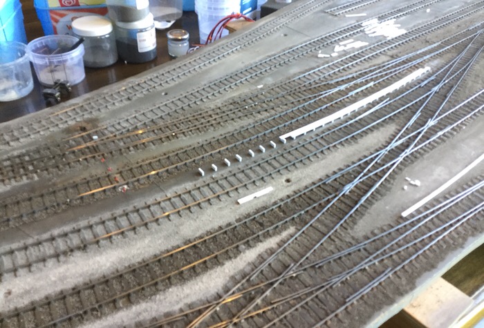 I’ll do a bit more of an update later this week if I can get round to it Kind regards Andrew |
||
| Last edited on 6 Aug 2018 08:11 by Andrew Duncan |
|||
|
posted: 8 Aug 2018 22:57 from: Andrew Duncan
click the date to link to this post click member name to view archived images |
Hello everyone Here’s a bit more detail of the ballasting I did whilst at Missenden. This is the sort of effect that I’m after generally within the station limits. So the line in the middle with dark we’ll kept ballast is the main up line and from photographs appears reasonably well looked after. The coach siding ( above it in the photo) and the goods yard are just ash by the look of it, up to sleeper top level and this I’ve found quite hard to achieve as yet. 2787_081711_350000000.jpg 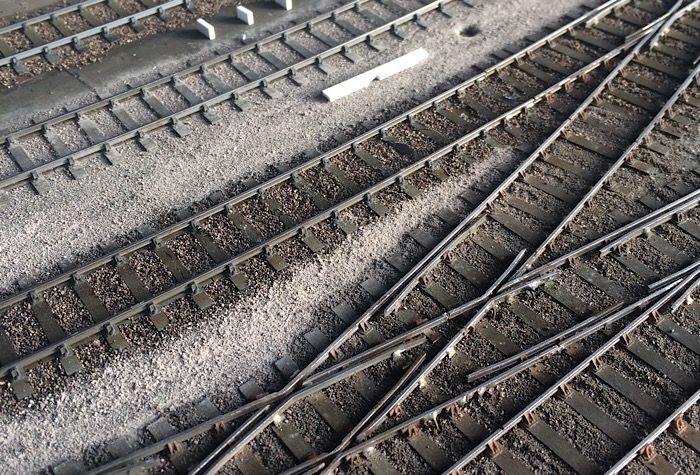 The photo below shows some progress since being back, with the walk way beside the carriage siding under construction made simply from Evergreen strip chopped up in my Northwest Shortlines chopper( a great tool for this sort of repetitive work). Next I need to work out how to do the road surfaces between the sidings in the goods yard which, in this scale, needs the barest minimum of texture to suggest what would have been a pretty smooth surface. Gloss paint and talcum powder have been suggested to me, so that’s one option that sounds feasible. Better reread Gordon Gravetts book on the subject! 2787_081738_340000000.jpg 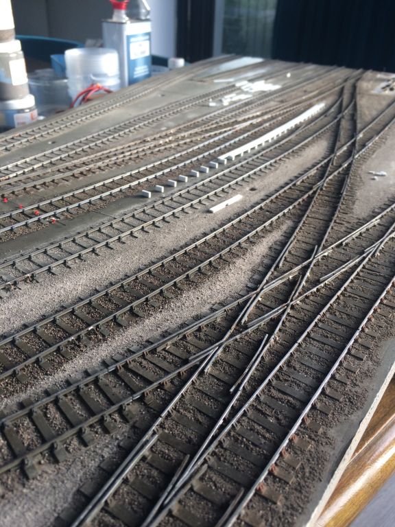 Kind regards Andrew |
||
|
posted: 8 Aug 2018 23:09 from: Martin Wynne
click the date to link to this post click member name to view archived images |
Andrew Duncan wrote:Gloss paint and talcum powder have been suggested to me, so that’s one option that sounds feasible. Better reread Gordon Gravetts book on the subject!Hi Andrew, Or gloss paint and chinchilla dust (from pet shops). It has just a fraction more texture than talcum powder, and is a useful material all round the layout for roadways, tarmac, etc. Good to see your progress. cheers, Martin. |
||
|
posted: 10 Aug 2018 07:20 from: Andrew Duncan
click the date to link to this post click member name to view archived images |
Martin Wynne wroteHi Andrew,Hello Martin Interesting stuff chinchilla dust. I tried some whilst I was at Missenden and although finer than the finish in the photos above, it was still a little coarse to my eye. The look I’m trying for is in this photo taken from the road bridge at the end of the platforms south end of the station. Looks very smooth at that distance with just the odd lump of detritus here and there. 2787_100216_220000000.jpg 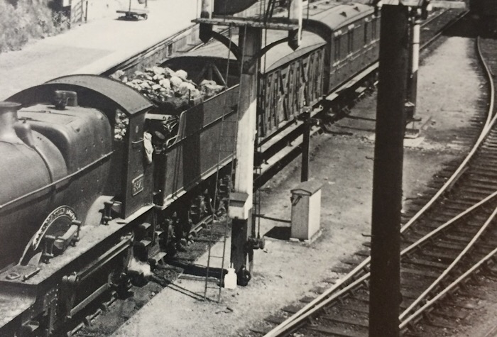 Thanks for your for your encouragement. Kind regards Andrew |
||
|
posted: 10 Aug 2018 13:40 from: Phil O
click the date to link to this post click member name to view archived images |
Hi Andrew, Have you tried wood ash? This tends to be pretty fine, although you may need to sieve out bits of charcoal, where the wood has not fully burnt. Phil. |
||
|
posted: 10 Aug 2018 14:01 from: Martin Wynne
click the date to link to this post click member name to view archived images |
Andrew Duncan wrote:Interesting stuff chinchilla dust. I tried some whilst I was at Missenden and although finer than the finish in the photos above, it was still a little coarse to my eye.Hi Andrew. How to make dried chinchilla dust smoother: http://www.sealantsandtoolsdirect.co.uk/manufacturers/sealants_and_tools_direct/sandtd_decorating_products/wallpaper_and_flashing_seam_roller_P27836.html A useful tool around the layout. Martin. |
||
|
posted: 10 Aug 2018 23:07 from: Andrew Duncan
click the date to link to this post click member name to view archived images |
Phil O wroteHave you tried wood ash? This tends to be pretty fine, although you may need to sieve out bits of charcoal, where the wood has not fully burnt.Hello Phil Yes I have in past but not on this occasion. And you’re right it may need sieving but depending on how lumpy it is may determine whether I need to sieve or not. I know I’ve got some somewhere, I’ll give it a try and let you know. Thanks for the idea. Kind regards Andrew |
||
|
posted: 10 Aug 2018 23:18 from: Andrew Duncan
click the date to link to this post click member name to view archived images |
Martin Wynne wrote:How to make dried chinchilla dust smoother: direct/sandtd_decorating_products/wallpaper_and_flashing_seam_roller_P27836.htmlHello Martin Neat idea. Think I may have one of these somewhere in the cellar. Might work well with the ash idea as well? Many thanks Andrew |
||
| Last edited on 11 Aug 2018 06:48 by Andrew Duncan |
|||
|
posted: 11 Aug 2018 00:35 from: John Palmer click the date to link to this post click member name to view archived images |
I have found a pestle and mortar a useful way of reducing the grain size of ballast and other scenic materials. A woman's stocking can be used to control the application of powdery materials. I recently tried the Gravett technique of talc on wet gloss paint to simulate a tarmac surface with some success, although the texture can be vulnerable to subsequent unwanted abrasions. Getting the yard surface up to top of sleeper height has been a problem for me too. Since the track concerned is being constructed in situ I still have the option of applying Das clay or the like around the sleepers that have been glued in place before fixing chairs and rails to the sleepers. I suspect that trying to build up the ground after the rail is in place might well lead to unacceptable results. However, this particular project (part of my planned West Highland layout) has gone on the back burner with I grapple with the revival of a forty-year old layout, the trackwork on which was finished long ago. |
||
|
posted: 11 Aug 2018 07:43 from: Andrew Duncan
click the date to link to this post click member name to view archived images |
Hello John Thanks for the pestle and mortar idea and yes I tried the stocking idea with the chinchilla dust for the first time last week but still found it too coarse. Maybe with Martins idea of a roller to flatten the lumpy bits that may now work. As I don’t have any chinchilla material (lasts weeks experiment was borrow from a friend) I’ll try the wood ash through a stocking and roller it flat where necessary and see how that comes out Watch this space! Kind regards Andrew |
||
|
posted: 11 Aug 2018 07:57 from: Andrew Duncan
click the date to link to this post click member name to view archived images |
Hello again John I forgot to reply to your thought on ground levels. I thought I’d try just building up the ground between sidings with card cut, of course, to shape from a spare print out of the area that Templot can provide at the push of a button. This is when I’ll find out how closely I’ve laid my track to the Templot plan! As to the ballast levels between the rails this is less of a problem. The bit outside the rails between the sleepers may well have to done manually with dilute PVA and ash. Laborious but for areas at the front of the layout probably worth doing Incidentally I’ve got a long barrow crossing to make through point work and I’ll try the print out technique there as well. Might save a lot of time. Andrew |
||
| Last edited on 11 Aug 2018 09:07 by Andrew Duncan |
|||
|
posted: 11 Aug 2018 13:17 from: Nigel Brown click the date to link to this post click member name to view archived images |
I'm a sucker for ready to use stuff. On the yard on my 3mm layout I used some stuff from Greenscene called textured paint; Squires sell it, £3.79 for a 125 ml bottle. Comes in various colours, mainly shades of grey. The colour doesn't matter, as I paint it once dry with dilute acrylics. The paint, being acrylic, can also be diluted with water, useful if you want it easier to work with. Re raising the yard level, I've just bought some 3mm thick foamboard; you get loads in a pack of A1 sheets, for not a lot of money. Can think of various uses. Nigel |
||
|
posted: 12 Aug 2018 19:46 from: Ian Allen
click the date to link to this post click member name to view archived images |
Andrew, I don't know if this is of interest to you: t_yeovil_pen_mill.jpg http://www.ukrailwayana.com/ At Stafford Railwayana Auctions. It didn't sell in May. Ian http://www.ukrailwayana.com/ At Stafford Railwayana Auctions. It didn't sell in May. Ian |
||
| Last edited on 12 Aug 2018 19:47 by Ian Allen |
|||
|
posted: 13 Aug 2018 05:32 from: Andrew Duncan
click the date to link to this post click member name to view archived images |
Nigel Brown wrote: I'm a sucker for ready to use stuff. On the yard on my 3mm layout I used some stuff from Greenscene called textured paint; Squires sell it, £3.79 for a 125 ml bottle. Comes in various colours, mainly shades of grey. The colour doesn't matter, as I paint it once dry with dilute acrylics. The paint, being acrylic, can also be diluted with water, useful if you want it easier to work with.Hello Nigel The textured paint sound interesting. Is it like a fine version of Sandtex the exterior paint? Have you, by chance, got a close up photo of it that you could post? Foam board would I think be too thick for my purposes here. I only need to pack it up just over half a mill to get top of sleeper height as I’m using the thin sleepers which I think are 0.8mm thick. Kind regards Andrew |
||
|
posted: 13 Aug 2018 09:57 from: Graham Idle
click the date to link to this post click member name to view archived images |
Hello Andrew, How about using greyboard as a packing material. It's available in a variety of thicknesses, 600micron, 750micron or 800micron might be just right. I can recommend ( http://www.funkypen.co.uk/GREYBOARD1.html ) as I have them before. Regards, Graham Nigel Brown wrote:I'm a sucker for ready to use stuff. On the yard on my 3mm layout I used some stuff from Greenscene called textured paint; Squires sell it, £3.79 for a 125 ml bottle. Comes in various colours, mainly shades of grey. The colour doesn't matter, as I paint it once dry with dilute acrylics. The paint, being acrylic, can also be diluted with water, useful if you want it easier to work with. Hello Nigel |
||
| Last edited on 13 Aug 2018 10:01 by Graham Idle |
|||
|
posted: 13 Aug 2018 13:32 from: Nigel Brown click the date to link to this post click member name to view archived images |
Andrew Duncan wrote
528_130823_580000000.jpg 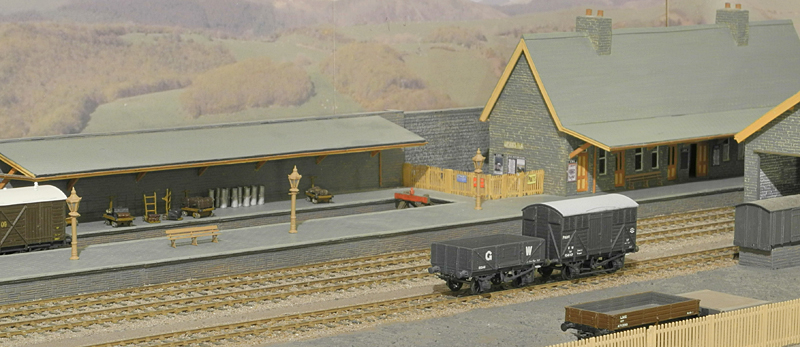 528_130826_030000000.jpg  It's used in the goods yard. The first pic is as laid, the second has various washes of dilute acrylic paint sloshed on it. The focus in the second pic is a bit odd; everything is a bit out of focus. As it comes it's a bit thick, and can dry out a bit in the bottle becoming a bit thicker, but it can easily be thinned using water. Goes on fairly easily; you need to work it a bit to avoid clumping. But you can get it pretty smooth with just the odd "stone" showing. Nigel |
||
|
posted: 13 Aug 2018 23:00 from: Andrew Duncan
click the date to link to this post click member name to view archived images |
Hello Nigel Thanks for the pictures, nice layout and very neat trackwork. I can see what you mean about effect you’ve got in the goods yard which although as you say is a little unfocused it has a good feel. Have you written up the construction of the layout anywhere on here or any of the other forums? I’d be most interested to see more, there aren’t many 3mm layouts around and I presume much of it youve built from scratch? Thanks again Kind regards Andrew |
||
|
posted: 13 Aug 2018 23:22 from: Andrew Duncan
click the date to link to this post click member name to view archived images |
2787_131835_110000001.jpg 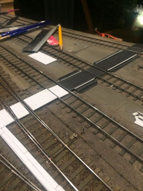 A ,little more progress over the weekend and this evening. I’ve finished the carriage siding walk way now and made a good start on the barrow crossing for which I used Evergreen v groove board which was a bit of a cheat not using separate planks for it, but I think it’ll look ok when finished? It’s quite long and an odd mix of planked surface and then where it crosses the sidings they just used ash built up,to height. So for that I’ve sanded three layers of plastics Into the rough shape and I’ll use some filler to smooth it out finallyA couple of pictures below to show what I mean. 2787_131835_110000000.jpg 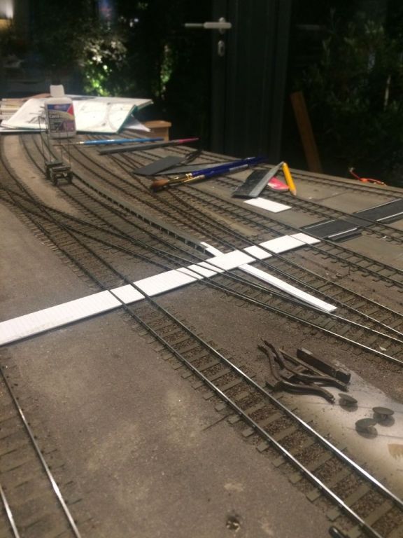 Andrew |
||
| Last edited on 13 Aug 2018 23:37 by Andrew Duncan |
|||
|
posted: 13 Aug 2018 23:44 from: Martin Wynne
click the date to link to this post click member name to view archived images |
Hi Andrew, I have rotated the pictures for you. The answer when using a phone camera is to turn it the other way up. The camera lens on the back should be at the top. If you use the the phone near-horizontal, first tip it up vertical and then back down. The orientation sensors don't work while the phone is horizontal. cheers, Martin. |
||
|
posted: 14 Aug 2018 00:33 from: Nigel Brown click the date to link to this post click member name to view archived images |
Andrew Duncan wrote: Hello Nigel Hi Andrew No write-up yet, partly because I'm a slow builder! I get side tracked by building rolling stock. Some pics have appeared in Mixed Traffic, the 3mm Society newsletter, and on RMweb. At the moment I'm forcing myself to build the cassettes for the fiddle yard, which I've been avoiding for years. Once that's done I can retest the whole of the trackwork then it's a question of finishing off the scenery. The first board (essentially the second pic) just needs scenic details, there's more to do on the shorter second board. The buildings are scratch built, the stock mainly from kits. The coaches in the second pic are a clerestory composite from Blacksmith and a toplight brake third from Worsley Works etches. The Dukedog is a Blacksmith body on my own etched chassis. For wagons the Society has a large offering mainly from Parkside, some Cambrian models, and a few other sources. More 3mm stuff can be found on http://sites.google.com/site/3mmpublic/ Nigel |
||
|
posted: 14 Aug 2018 01:20 from: Rob Manchester
click the date to link to this post click member name to view archived images |
Hi Andrew, If you want very fine powder to mix with paint etc for textured surfaces you could try Aluminium Oxide powder. It is often sold for air-eraser guns used to clean paint/rust/etc of equipment or models. HTH Rob |
||
|
posted: 14 Aug 2018 22:48 from: Andrew Duncan
click the date to link to this post click member name to view archived images |
Martin Wynne wrote: Hi Andrew,Thanks Martin Oddly enough I think I did have the phone held upright / portrait but obviously got something wrong? Andrew |
||
|
posted: 14 Aug 2018 23:01 from: Andrew Duncan
click the date to link to this post click member name to view archived images |
Rob Manchester wrote: Hi Andrew,Hello Rob Thanks for the idea. If the stuff I have in stock doesn’t satisfy then I’ll give your idea a go. First I’m going to try wood ash and possibly a roller if necessary which I anticipate will give me a bit more variation then talc. Then we’ll see! Earlier this evening I was trying packing up the ground level to sleeper top height with thin card. A lot of work which ended up in the bin eventually! Nothing ventured nothing gained. Kind regards Andrew |
||
|
posted: 14 Aug 2018 23:28 from: Andrew Duncan
click the date to link to this post click member name to view archived images |
Ian Allen wrote: Andrew, I don't know if this is of interest to you: t_yeovil_pen_mill.jpgHello Ian Lovely sign but rather outside my pocket at present, I suspect. Thanks for thinking of me. Kind regards Andrew |
||
|
posted: 15 Aug 2018 00:24 from: Rob Manchester
click the date to link to this post click member name to view archived images |
Andrew Duncan wrote:
Andrew, I have talked to people who have built models with goods yards, carriage sidings and the like in the past and they often use very thin sleeper material in the parts that will be ballasted to the sleeper tops. I seem to remember one chap used 30 thou plasticard 'timbers' on the normal track and switched to 10 thou on the ones where the ground level was to be nearly up to the sleeper tops. 10 thou ( 0.010" ) is about 0.75 inches in 4mm scale which could be suitable. Maybe try that on Yeovil Town Regards Rob |
||
|
posted: 16 Aug 2018 21:07 from: Andrew Duncan
click the date to link to this post click member name to view archived images |
Rob Manchester wroteAndrew,Hello Rob That’s a really good idea and thank you passing this idea on...if only I’d thought of doing this before! BUT as I’ve alread laid the track I think my compromise will be to try a layer of PVA and ash and if that looks ok great. If it still looks a bit low I’ll try another layer of glue and ash. I’ll post a photo once done and you can judge for yourself how it’s come out. Thanks again Kind regards Andrew |
||
|
posted: 16 Aug 2018 22:44 from: Rob Manchester
click the date to link to this post click member name to view archived images |
Andrew, The track that is laid on the thinner sleepers has packing underneath to make the rail to baseboard height the same as the normal height sleepers. Just in case anybody was thinking of the layout looking like it was suffering the roller coaster effect Keep up the good work with the layout - it is looking good. Rob |
||
|
posted: 17 Aug 2018 08:18 from: Andrew Duncan
click the date to link to this post click member name to view archived images |
Rob Manchester wrote: Andrew,Hello Rob Thanks for your comments and encouragement, much appreciated. I also wondering if in building the track for the next baseboard I do as you suggest with the thin sleepers? The only problem that I foresee in doing this maybe in trying to match the two different approaches in construction at the baseboard joint and I suppose in the overall in the look. I shall have to see how the ash on PVA works and take it from there. Kind regards Andrew |
||
|
posted: 17 Aug 2018 12:32 from: Nigel Brown click the date to link to this post click member name to view archived images |
If you need a source of thin sleepers, I'd suggest looking at Plastruct and Evergreen strip. I've used them entirely on my 3mm layout, although in my case they're not thin. Plastruct and Evergreen are slightly different materials, so you need to check that the solvent you use works on whatever you choose. Nigel |
||
|
posted: 17 Aug 2018 18:34 from: Tony W
click the date to link to this post click member name to view archived images |
The track in goods yards and sidings was often lower than the adjacent running lines anyway. I achieved this effect by using 1/16" cork underlay for the sidings and 1/8" cork under the running lines. The difference was achieved by sanding the thicker cork down to match over a foot or so. The sleepers were of the same thickness 1/32" ply. Regards Tony. |
||
|
posted: 19 Aug 2018 08:34 from: Andrew Duncan
click the date to link to this post click member name to view archived images |
Nigel Brown wrote: If you need a source of thin sleepers, I'd suggest looking at Plastruct and Evergreen strip. I've used them entirely on my 3mm layout, although in my case they're not thin. Plastruct and Evergreen are slightly different materials, so you need to check that the solvent you use works on whatever you choose.Hello Nigel Yes I think I’d be inclined to this route with Evergreen as that’s what I normal use and probably have in stock. A ndrew |
||
|
posted: 19 Aug 2018 12:53 from: Andrew Duncan
click the date to link to this post click member name to view archived images |
Tony W wrote: The track in goods yards and sidings was often lower than the adjacent running lines anyway. I achieved this effect by using 1/16" cork underlay for the sidings and 1/8" cork under the running lines. The difference was achieved by sanding the thicker cork down to match over a foot or so. The sleepers were of the same thickness 1/32" ply.Hello Tony As far as I can tell the main line and goods yard are all at the same level at Yeovil which makes life simpler. But I wasn’t aware that this was often the case. Do you know why they would make goods yards lower? Andrew |
||
|
posted: 19 Aug 2018 13:28 from: Martin Wynne
click the date to link to this post click member name to view archived images |
Andrew Duncan wrote:Do you know why they would make goods yards lower?Hi Andrew, Unbraked vehicles don't roll away uphill. Gravity has nothing to go wrong and never fails. cheers, Martin. |
||
|
posted: 19 Aug 2018 13:47 from: Nigel Brown click the date to link to this post click member name to view archived images |
I wondered if that's why Machynlleth yard had two hefty Iron Minks used as buffer stops! | ||
|
posted: 19 Aug 2018 15:19 from: Tony W
click the date to link to this post click member name to view archived images |
Andrew Duncan wrote: Tony W wrote:Hi Andrew. As Martin has already explained, it is for safety reasons. Although the exit from the yard would be protected by Safety points, it is better not to allow vehicles to roll away toward them in the first place, with all the attendant problems that would cause.The track in goods yards and sidings was often lower than the adjacent running lines anyway. I achieved this effect by using 1/16" cork underlay for the sidings and 1/8" cork under the running lines. The difference was achieved by sanding the thicker cork down to match over a foot or so. The sleepers were of the same thickness 1/32" ply.Hello Tony As far as I can tell the goods yard of my current modelling project Brimsdown wasn't lower than the running lines either. Nor was the siding adjacent to the running line at the regulation track centres being standard track spacing as far as I can tell. Regards Tony. |
||
|
posted: 19 Aug 2018 21:57 from: Ariels Girdle click the date to link to this post click member name to view archived images |
Does it not have something to do with ballasting too - at least in recent times? Main lines tend to be deep-ballasted whereas sidings usually have little or none at all. | ||
|
posted: 20 Aug 2018 00:09 from: Andrew Duncan
click the date to link to this post click member name to view archived images |
Tony W wroteHi Andrew. As Martin has already explained, it is for safety reasons. Although the exit from the yard would be protected by Safety points, it is better not to allow vehicles to roll away toward them in the first place, with all the attendant problems that would cause.Hello Martin and Tony Very sensible and practical idea. Great stuff gravity, utterly reliable. Thanks for the explanation. Andrew |
||
|
posted: 27 Aug 2018 21:35 from: Andrew Duncan
click the date to link to this post click member name to view archived images |
Hello everyone A bit more progress over the last few days. I’ve played around with ground surface between the sidings which is ok but still not quite right, but I think I’m gradually getting there. I’ve been looking around to see if anyone does a locally hand operated point lever, the type thats attached directly to the turnout in goods yards and mpds and operated by the shunter or fireman. I couldnt see that anyone did, so flushed with bravery from watching some really excellent modellers at work at Missenden I thought they’d couldn’t be too hard to fabricate myself. By chance Iain Rice was up our way last weekend and popped in that Saturday to see how I was getting on. I asked him how he’d do it and to cut not too long a story short, we came up with a simple solution. I extended the sleepers either side of the tie bar by about 3 scale feet. Cut some plastic strip to represent the planks covering the tie bar. Drilled a hole in the baseboard at about the angle of the point lever at rest. Fashioned the lever out of brass T angle with one side(viewing side) filed flat, the other side I left to add strength and filed the top roundish to represent the handle. Crude, but to my eye ok I think; you can judge for yourself. Then guesstimating from one of the Wild Swan books on GWR branchlines I bent up some 0.9mm steel wire for the guard ( what was that guard for? Was it to keep ropes clear of the lever when using horses to pull wagons around?) into a squared off C, drill two holes in the baseboard for them to be planted in. This stuff is pretty robust and as I’ve already damaged my newly installed point rodding I thought I wanted something pretty tough as its a lot more vulnerable than the rodding. Then, as I was on a roll, l assembled two of the rather nice LMS GWR cast buffer stops for a siding in the marshalling yard and one at the end of the carriage siding that sits between the up and down lines. I made the first one up free hand but it was a bit nail biting so for the second one I made up a very simple jig which allowed me to finish the model and spray it before installing it. Well The Bridge is calling me now, I refer to the Danish / Swedish detective series not he Abbotsbury road bridge. Here are a couple of pictures which may help in understanding my description 2787_271629_190000000.jpg 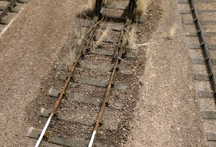 I don’t know what I’ve done to this photo. I’ll try again later and include the point lever as well. Kind regards Andrew |
||
|
posted: 28 Aug 2018 00:34 from: Andrew Duncan
click the date to link to this post click member name to view archived images |
Here are a couple more pictures. This one shows the point lever installed. 2787_271909_510000000.jpg 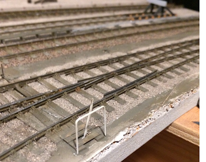 And this one the end of the carriage siding buffer stop. 2787_271920_240000000.jpg 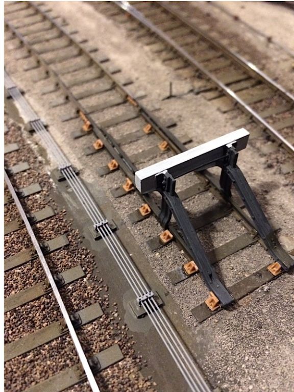 And lastly the other buffer stop with some rather overgrown grass that needs a trim and perhaps a little green colour added sparingly. 2787_271928_220000000.jpg 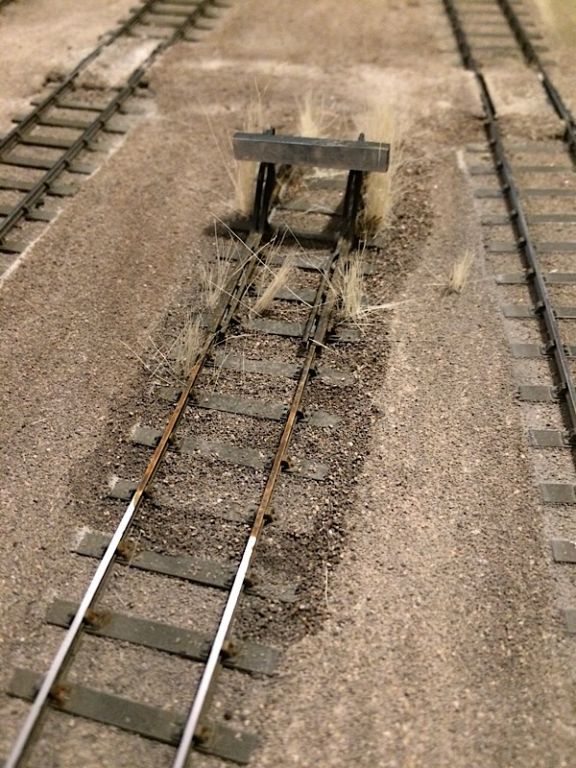 |
||
|
posted: 28 Aug 2018 01:06 from: Nigel Brown click the date to link to this post click member name to view archived images |
Think the ground surface is looking good. Having the colour not too dissimilar to the ballast is the right way to go; mine at the moment is a bit too grey and needs some dilute earth sloshed onto it. Somebody does do a kit for hand levers but can't remember who. But yours looks fine anyway. Must try it myself! |
||
|
posted: 28 Aug 2018 08:11 from: Phil O
click the date to link to this post click member name to view archived images |
Dornaplas/Springside Models do point levers,I can't remember if they are straight or curved levers though. Phil |
||
|
posted: 28 Aug 2018 09:06 from: John Shelley
click the date to link to this post click member name to view archived images |
Nigel Brown wrote: Think the ground surface is looking good. Having the colour not too dissimilar to the ballast is the right way to go; mine at the moment is a bit too grey and needs some dilute earth sloshed onto it. Somebody does do a kit for hand levers but can't remember who. But yours looks fine anyway. Must try it myself!Ambis Engineering do point hand levers. http://www.ambisengineering.co.uk/ I couldn't find them on the site, but they are in the price list, which is downloadable. Cheers for now John frrom 33820 St Ciers sur Gironde |
||
|
posted: 28 Aug 2018 10:13 from: John Palmer click the date to link to this post click member name to view archived images |
Various designs of levers are available as etched kits from Roxey Mouldings as part of the Southwark Bridge Models range - see this page. The kits are quite fiddly to assemble and a good test for your soldering capabilities (well, that's what I found with the Summerson lever), but produce a most acceptable result. I guess that on the full size railway the most commonly used lever reproduced in the Southwark Bridge range is the Wiliams, two of which I have just purchased for our Burnham layout. |
||
| Last edited on 28 Aug 2018 13:49 by John Palmer |
|||
|
posted: 28 Aug 2018 20:02 from: Andrew Duncan
click the date to link to this post click member name to view archived images |
Hello Nigel Thanks for the thoughts and the compliment. Looks like Phil has remembered that they come from Dornaplas. Are they the ones you were thinking of? Andrew |
||
|
posted: 28 Aug 2018 20:06 from: Rob Manchester
click the date to link to this post click member name to view archived images |
Andrew, Wizard Models - Andrew can supply these levers : Yard Levers Bet they are cheaper than the others mentioned Rob |
||
| Last edited on 28 Aug 2018 20:08 by Rob Manchester |
|||
|
posted: 28 Aug 2018 20:12 from: Andrew Duncan
click the date to link to this post click member name to view archived images |
Thanks PhilKind regards Andrew |
||
|
posted: 28 Aug 2018 20:17 from: Andrew Duncan
click the date to link to this post click member name to view archived images |
John ShelleyThanks for the info John. I too thought they did them, but couldn’t see them when I looked at his website. Didnt occure to me to look at the price list!Kind regardsAmbis Engineering do point hand levers. Andrew |
||
|
posted: 28 Aug 2018 20:22 from: Andrew Duncan
click the date to link to this post click member name to view archived images |
John Palmer wrote: Various designs of levers are available as etched kits from Roxey Mouldings as part of the Southwark Bridge Models range - see this page.Hello JohnThanks for the info, must admit I didn’t think of Roxey when doing my search Kind regards Andrew |
||
|
posted: 28 Aug 2018 20:25 from: Andrew Duncan
click the date to link to this post click member name to view archived images |
Rob Manchester wrote: Andrew,Hello RobThanks for the info and yes they do appear very good value. Seems I’m now spoilt for choice! Kind regards Andrew |
||
|
posted: 28 Aug 2018 23:04 from: Nigel Brown click the date to link to this post click member name to view archived images |
Andrew Duncan wrote: Hello Nigel Not sure. some were reviewed in Mixed Traffic, the 3mm Society quarterly magazine; wasn't sure if they were 3mm or 4mm. Am trying to find out scale and origin! I'll need some. If not, I'll follow your method. Nigel |
||
|
posted: 4 Sep 2018 21:44 from: Andrew Duncan
click the date to link to this post click member name to view archived images |
Hello I’ve gone underground as break from trying to achieve road surface perfection and am doing a rewire. Whilst at Missenden I realised that I had to do something about my ability to do electrical fault finding on the layout generally and on this baseboard in particular, as it’s has 11 turnouts and two diamonds all of which need their crossings polarity changed reliably. When this little lot goes wrong ( and it has several times already) I’d found it extremely difficult to trace where the problem came from. Now had I thought this through I’d have thought of having the layout split up into districts but somehow I’d just thought each baseboard would be a separate district. But as I’ve indicated above this isn’t adequate. So discussing it with Tim at Missenden I decided to adopt a pretty standard approach of separate districts for Up and Down lines and then further separate the line to Yeovil Town and keep the goods and marshalling yards separate, totalling 4 districts. 2787_041650_460000000.jpg 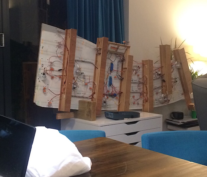 So now I’ve just about completed the rewire (see the picture above). The three districts that occur on this board all go to terminal blocks screwed to the underside of the board which in itself is much better than my previous arrangement. From there the 3 pairs of wires will feed through to an 8 pin DIN socket which in turn will be fed from the 4 district buses running round the layout. That’s about it for now Kind regards Andrew |
||
| Last edited on 4 Sep 2018 21:51 by Andrew Duncan |
|||
|
posted: 5 Sep 2018 09:25 from: Tony W
click the date to link to this post click member name to view archived images |
Hi Andrew. Yes, it is all to easy to be seduced by the 'all you need is two wires' argument of DCC. All very well when things work, not so great when they don't, as you have evidently discovered. Regardless of whether using DCC or conventional DC control systems, the ability to be able to easily break down the electrical system into smaller subsections to aid fault finding is invaluable and in my view, much under appreciated. I tend to go further than you have and connect all my point motors, which include the polarity switching for the crossings, via plug in connectors. Although this is primarily done to enable a point motor to be replaced relatively easily if needs be, this also makes it a lot easier to disconnect any individual crossing in the event of trying to localise a short. Diamonds tend to be a common source of shorts as it is often possible to run through either road regardless of how the crossing polarity is set. However the crossings will only be correct for one road unless the settings of the approach roads are carefully thought about to avoid this. Effectively incorporating some basic interlocking. Regards Tony. |
||
|
posted: 6 Sep 2018 22:37 from: Andrew Duncan
click the date to link to this post click member name to view archived images |
Tony W wrote: I tend to go further than you have and connect all my point motors, which include the polarity switching for the crossings, via plug in connectors. Although this is primarily done to enable a point motor to be replaced relatively easily if needs be, this also makes it a lot easier to disconnect any individual crossing in the event of trying to localise a short. Hello Tony Having decouplable point motors is a good idea I agree. When first planning this layout I was going to use the modern version of the Tortoise ( the name temporarily eludes me, but you know the blue one) and a friend had designed a plug in base which would have had a plug connection and been removable from above...no crawling around underneath ( trust you’re impressed?). I fear that in falling in love with Dave Fenton’s Megapoint servo control which takes much less space on top but is mounted underneath dashed all that planning and ease of replacement. Having said that I have used the Wago connectors to attach the crossing polarity wires to the micro switches ( making them unplayable) and of course the servos them selves by default come with plugs on their leads. It’s not the same as an unpluggable assembly however and only time will tell whether servos are more reliable than other forms of point motor. I am actually quite concerned about the micro switches( also operated by the servos) not being held in place once the blades have been thrown. This is partly because the latest version of the software switches off after a second after it’s thrown the blades and does no further checking on the servo until it’s asked to switch back again. And partly perhaps because the servos I’ve used have the standard lenght arm; would a long arm with great leverage be the answer? This means I get no twitching and chatter from the servos which is a blessed relief, but I also understand that there’s no power to keep it in position and with the micro switch pushing against the servo arm my fear is that it may allow the switch to return to the opposite/ wrong polarity for that road. Diamonds tend to be a common source of shorts as it is often possible to run through either road regardless of how the crossing polarity is set. However the crossings will only be correct for one road unless the settings of the approach roads are carefully thought about to avoid this. Effectively incorporating some basic interlocking.So I’m not sure if I’m making sense here, but I think I may end up using Frog Juicers of some sort to change the crossings polarity...certainly easier for diamonds! But at this point I’ve stuck to micro switches throughout and we’ll see how things go. What I haven’t addressed is your thought on interlocking. I’d be interested to know if you feel that frog juicers would obviate the need for interlocking? Thanks for your continued thoughts and advice, both much appreciated. Kind regards Andrew |
||
|
posted: 7 Sep 2018 07:21 from: Andrew Barrowman
click the date to link to this post click member name to view archived images |
Andrew Duncan wrote: I am actually quite concerned about the micro switches( also operated by the servos) not being held in place once the blades have been thrown. This is partly because the latest version of the software switches off after a second after it’s thrown the blades and does no further checking on the servo until it’s asked to switch back again. And partly perhaps because the servos I’ve used have the standard lenght arm; would a long arm with great leverage be the answer? This means I get no twitching and chatter from the servos which is a blessed relief, but I also understand that there’s no power to keep it in position and with the micro switch pushing against the servo arm my fear is that it may allow the switch to return to the opposite/ wrong polarity for that road.Hi Andrew, It's good that you are concerned. I could write a book about the misapplication of servos in a model railway environment but I'm pretty sure, even if it was free, nobody would bother to read it If you want to reduce the pressure on the servo from the microswitch you should use the shortest possible servo arm. That will minimize the torque that's tending to rotate the servo. Likewise with the mechanism that acts on the points. What you really want to do is make the servo rotate through the greatest possible angle. If the actuator arm rotates through 140 degrees it is almost impossible for the points to "back-drive" the servo. The "pulse disable" feature that's intended to prevent twitch (which btw can also result in gigantic excursions capable of destroying tie-bars etc.) is a kludge. The servo is still receiving power and if there is sufficient interference the servo can head for never-never land and stay there. It's also a "roll of the dice". The drive pulses to the servo are only disabled after a delay. If interference strikes while the pulse stream is active the servo can assume an indeterminate position which will not be corrected if the pulse stream stops. I can make servos operate with total reliability but it involves messing around with some electronics. Not a lot, but it seems to be much more than anyone wants to deal with. Servos are seductive, but if you just want everything to work without a lot of potential aggravation, don't touch them. Cheers, Andy |
||
| Last edited on 7 Sep 2018 08:20 by Andrew Barrowman |
|||
|
posted: 7 Sep 2018 08:11 from: Martin Wynne
click the date to link to this post click member name to view archived images |
Andrew Barrowman wrote:but if you just want everything to work without a lot of potential aggravation, don't touch them.And the same for microswitches, the installation and adjustment of which is a form of cruelty in contravention of the Geneva Convention. To switch the polarity of a V-crossing, use a sugar-cube relay. They cost very little more than a microswitch. They can be installed anywhere you like with just a dab of the glue gun. Given the typical model railway use, they will last forever and never need any attention whatsoever -- you can safely bury them under the scenery. If you have an all-mechanical lever-frame setup for operating the points, all a relay needs is an on-off switch, not a changeover. That can be very easily contrived by grounding the frame, and having an insulated bit of springy wire making contact with the lever or rodding somewhere in the run. The contact quality is irrelevant for a low-voltage relay and will have no effect on the train running over the crossing. Martin. |
||
|
posted: 7 Sep 2018 23:40 from: Andrew Duncan
click the date to link to this post click member name to view archived images |
Andrew Barrowman wrote: Andrew Duncan wrote:Hello AndyI am actually quite concerned about the micro switches( also operated by the servos) not being held in place once the blades have been thrown. This is partly because the latest version of the software switches off after a second after it’s thrown the blades and does no further checking on the servo until it’s asked to switch back again. And partly perhaps because the servos I’ve used have the standard lenght arm; would a long arm with great leverage be the answer? This means I get no twitching and chatter from the servos which is a blessed relief, but I also understand that there’s no power to keep it in position and with the micro switch pushing against the servo arm my fear is that it may allow the switch to return to the opposite/ wrong polarity for that road.Hi Andrew, Thanks for your thoughts on how to avoid the back drive on the servo from the microswitch which I will look into to see how much more rotation I can achieve with the existing servo brackets. I think I’ll have to move the control wire either in or out along the servo arm to achieve the extra rotation. If I feel that it’s still going to be a problem then I’ll either take Martins advice or go the frog juicer route. As to ripping them all out and going back to Cobalts or something more conventional, this thought doesn’t fill me with joy and I’d like to prove to myself that I can do it. Time will tell! Kind regards Andrew |
||
| Last edited on 8 Sep 2018 06:48 by Andrew Duncan |
|||
|
posted: 7 Sep 2018 23:47 from: Nigel Brown click the date to link to this post click member name to view archived images |
Andrew Duncan wrote: Hello AndyBest of luck. I'd like to go with servos in future so I'll be following your progress with interest. Other options like Tortoises have their own drawbacks. I've used servos successfully on a couple of signals, but these don't quite have the same need to get the end points right. Nigel |
||
|
posted: 8 Sep 2018 00:07 from: Andrew Duncan
click the date to link to this post click member name to view archived images |
Martin Wynne wrote: Andrew Barrowman wrote:Hello Martinbut if you just want everything to work without a lot of potential aggravation, don't touch them.And the same for microswitches, the installation and adjustment of which is a form of cruelty in contravention of the Geneva Convention. I think I’ve heard you voice this reticence about microswitches before and I must say I’m beginning to feel that they are going to be a bit of a challenge to keep,adjusted correctly. Im wondering if I should just whip them out and try either your idea of relays or I’ve got three of the Gaugemaster frog juicer devices. They have a rating of only an amp,or two if I recall correctly. Is that likely to be problematic do you know when the power amp for the DCC is 5 amps? Typically my engines draw 0.3 to 0.4 of an amp. Kind regards Andrew |
||
|
posted: 8 Sep 2018 00:26 from: Andrew Duncan
click the date to link to this post click member name to view archived images |
Nigel wroteBest of luck. I'd like to go with servos in future so I'll be following your progress with interest. Other options like Tortoises have their own drawbacks. I've used servos successfully on a couple of signals, but these don't quite have the same need to get the end points right.Hello Nigel I’ll keep you posted on my progress. My initial experiences with the Megapoints control has been positive and certainly setting the end points has not been difficult with every control board being completely self contained with its own controls built in. The signal control even has bounce built in which varies every time by a small amount so no two returns to danger are the same. Very nice. What I’dont know yet is how it performs in regular use and that concerns me a bit. But, nothing ventured ....Kind regards Andrew |
||
|
posted: 8 Sep 2018 06:47 from: Andrew Duncan
click the date to link to this post click member name to view archived images |
Nigel BrownI've used servos successfully on a couple of signals, but these don't quite have the same need to get the end points right.Nigel realise that I don’t know and didn’t ask last night what system you are using for the signals and how does that work. I’d be very interested to know your experiences with another system. Andrew |
||
| Last edited on 9 Sep 2018 00:12 by Andrew Duncan |
|||
|
posted: 8 Sep 2018 07:13 from: Martin Wynne
click the date to link to this post click member name to view archived images |
Andrew Duncan wrote:I think I’ve heard you voice this reticence about microswitches before and I must say I’m beginning to feel that they are going to be a bit of a challenge to keep,adjusted correctly. I'm wondering if I should just whip them out and try either your idea of relays or I’ve got three of the Gaugemaster frog juicer devices. They have a rating of only an amp,or two if I recall correctly. Is that likely to be problematic do you know when the power amp for the DCC is 5 amps? Typically my engines draw 0.3 to 0.4 of an amp.Hi Andrew, In an ideal world, a crossing polarity switch never operates under load (i.e. with current flowing). So it needs only to be rated around 1 amp or so for the max likely loco current. In practice on a model railway, there are going to be times when it accidentally switches into a dead short condition, for example changing the crossing polarity when a wheel is bridging an isolation gap in the rails. So you need contacts which can handle that without being degraded. I suggest therefore that a relay contact needs to be rated around 5 or 10 amps or more for long term reliability. Looking at some of the contacts typically used by railway modellers I wouldn't be too happy about that -- for example the copper track wipers used inside a Tortoise point motor. Sorry, I know nothing about using small model servos. If you are saying that a microswitch is capable of pushing the arm back in standby condition, I'm puzzled to know how the servo is capable of holding the point blades against the stock rail? In fact looking at your servo installation: 2787_201839_300000000.jpg  it's not clear to me how it drives the points over? Is the top plate acting as a fulcrum for the drive rod? Whatever, all you need to operate a relay is to arrange something to make contact against something else as an improvised on-off switch. This is 100 times easier to do than improvising a changeover switch. For example an ordinary choc-block connector could have a bit of springy phos-bronze wire sticking out of it, which makes contact with the drive rod to the points in one position, and not the other. Connect the drive rod/bracket/whatever to the system ground (common return), and the springy bit of wire through the relay coil to the power supply. To be really posh you could add a reverse diode across the relay coil to quench any inductive sparking and keep the springy wire nice and clean, although even without I suspect it would work fine for 50 years without needing any attention. What you probably can't do is slave the relay directly across the servo connections (over to Andy on that) as you can do for example with a Tortoise point motor. If you buy relays on eBay from the far east you can get them for about 20p each in bulk packs. But I think I would prefer a branded product from a proper distributor, such as something like this: http://www.rapidonline.com/good-sky-rwh-ss-112d-12v-rwh-series-12a-spdt-relay-60-4668 or maybe something more rugged: http://uk.rs-online.com/web/p/non-latching-relays/2172876/ which are a lot cheaper than a frog juicer. There a dozens of types and coil voltages available (those are for 12v dc power supply). To install such a sugar-cube relay you just dab it with the glue gun anywhere you like under the baseboard. cheers, Martin. |
||
|
posted: 8 Sep 2018 08:21 from: Stephen Freeman
click the date to link to this post click member name to view archived images |
Good Morning, Martin - I think you would need latching relays for polarity changing. Servos are constantly powered (5vdc) direction speed etc is controlled by the signal, so I don't think powering a relay off that would work. Don't know the proposed method of controlling the switching of the servo but a dpdt switch could control the polarity as well. If you are worried about the servo switching off and the blades losing contact, then you have the blades too stiff. The servo will in fact still be powered, it's just that the control signal stops. If you need to have the servo constantly trying to hold its position with stiff blades and use a system which can do this (optional under MERGs Servo4 I think), you run the risk of burning out the servo motor and fairly rapid failure follows etc. In practice it is usually found (at least in my experience) that there is enough resistance in the servo motors gearing to hold the blades in position. If you want to use a Frog Juicer, I think I'm right in saying that TAM Valley ones can handle 5amps, in fact I seem to recall without checking that they are switchable between systems that are less than 5 amps and those that are 5 amps or more. I have some but still in their packets. |
||
| Last edited on 8 Sep 2018 08:28 by Stephen Freeman |
|||
|
posted: 8 Sep 2018 08:57 from: Martin Wynne
click the date to link to this post click member name to view archived images |
Stephen Freeman wrote: Don't know the proposed method of controlling the switching of the servo but a dpdt switch could control the polarity as well.Hi Stephen, I'm not worried about servos because I would never use one -- far too fragile and fiddly for me. My idea of a point motor is something like this: http://uk.rs-online.com/web/p/dc-d-frame-solenoid/9059944/ with a relay slaved across it for polarity switching. Adding a disc such as a jam pot lid to the linkage provides some air damping to slow it down and reduce shock. It doesn't need to be a latching relay, unless you also use a latching magnetic solenoid to save power consumption. Yes you could use a DPDT panel switch, but that then requires an additional wire connection in the cable to the control panel. A relay near the actual turnout is less trouble. But Andrew is using servos, using the Megapoints controller. I have no idea what the interface signals are for that, but almost certainly they don't allow the direct connection of a relay. Hence my suggestion of an improvised switch for the relay. I believe the servos are in fact unpowered in the stopped state, to prevent twitching from interference on the control line. cheers, Martin. |
||
|
posted: 8 Sep 2018 10:21 from: Andrew Howlett
click the date to link to this post click member name to view archived images |
I am using the MegaPoints system for my 0-gauge layout, but I am using the relay controller boards and relays (5A) working in conjunction with the servo controllers for switching the polarity on the crossings. I've used the shortest servo arms on the second or sometimes third hole to give the maximum rotation on the servo. I am very pleased with the MegaPoints system. Dave Fenton has bent over backwards to assist with getting my system to work correctly when I've had problems through not reading or understanding the installation instructions, although I did recently discover an error in the firmware on the MultiPanel controllers! Dave spent a whole weekend reproducing my system, reproducing the fault, rewriting part of the software to fix the problem, and sending me replacement controllers. How's that for service! Andrew Howlett. |
||
|
posted: 9 Sep 2018 00:17 from: Andrew Duncan
click the date to link to this post click member name to view archived images |
Hello MartinThanks for your replies to my questions. I’ve put mine in your text. Andrew Martin Wynne wrote Andrew Duncan wrote:I think I’ve heard you voice this reticence about microswitches before and I must say I’m beginning to feel that they are going to be a bit of a challenge to keep,adjusted correctly. I'm wondering if I should just whip them out and try either your idea of relays or I’ve got three of the Gaugemaster frog juicer devices. They have a rating of only an amp,or two if I recall correctly. Is that likely to be problematic do you know when the power amp for the DCC is 5 amps? Typically my engines draw 0.3 to 0.4 of an amp.Hi Andrew, In fact looking at your servo installation: Yes the top of the frame is the fulcrum and the operating wire goes through an 8mm hole in the baseboard to drive the switches Megapoints do have a board that will control relays which I’ve used on the junction board that I built before this one. I got in a bit of a muddle with it because I’m not very good at remembering where the wires were meant to go for some reason and on several occasions connected the wrong crossings to the switch. But I got there eventually and that works ok as it does for Andrew Howlett on his O gauge layout by the sound of it. The appeal of the individual frog juicers is the reduction in wiring with no wires longer than a turnout being involved, no remote switching or wiring going back to the Megapoints board. Downside is that I can’t test the layout in analogue mode as they don’t operate in DC. A bit more thought required I think. Thanks again. Andrew |
||
|
posted: 9 Sep 2018 00:33 from: Andrew Duncan
click the date to link to this post click member name to view archived images |
Andrew Howlett wrote: I am using the MegaPoints system for my 0-gauge layout, but I am using the relay controller boards and relays (5A) working in conjunction with the servo controllers for switching the polarity on the crossings. I've used the shortest servo arms on the second or sometimes third hole to give the maximum rotation on the servoHello Andrew Thanks for the feedback on your installation, its good to hear of an example which is up and running and working well. And I can echo your experience of Dave Fenton, he has been very helpful on a couple of occasions. One question for you, did you install the Megapoints relay control and relays themselves near the main control board or did you try to get them more locally placed to reduce wiring length. Kind regards Andrew |
||
| Last edited on 9 Sep 2018 00:39 by Andrew Duncan |
|||
|
posted: 9 Sep 2018 00:44 from: Martin Wynne
click the date to link to this post click member name to view archived images |
Andrew Duncan wrote:The appeal of the individual frog juicers is the reduction in wiring with no wires longer than a turnout being involved,Hi Andrew, The same applies to a relay if you mount it close to the turnout. The only extra wire to the board needed is a power supply for the relays, which would be 1 wire for the whole board. Or 2 wires, in the unlikely event that you don't already have a system ground (common return), for the servo power and items such as uncoupling magnets, lights in buildings, etc. cheers, Martin. |
||
|
posted: 9 Sep 2018 08:01 from: FraserSmith
click the date to link to this post click member name to view archived images |
Hi Andrew I have missed some of your recent postings as I'm away on a working trip so my response may not quite be the answer you want but I'm off out again soon and don't have the time to read back through all your postings. In your photo you show the operating wire in the top servo arm. It really should be through the bottom arm and a reasonable distance down. You then get less up and down movement of the wire. Where it goes depends on your baseboard thickness and scale. A thicker BB will have more movement of the operating wire than a thin one. N and 4mm will need about 2mm of movement at the tie bar height. Your O gauge will maybe be 3mm. Simple proportions can be used on the distances above and below the hole in the mounting plate of your servo mount. If the BB is say 20mm and you want 2mm travel up top and your wire goes through the horn at 25mm down your movement sideways will need to be 2.5mm (25/20*2). Frog juicers are an expensive tecchie solution to a problem that should never occur. If you know which way the point is set then you know the polarity of the frog that's needed. It can be switched with one microswitch as you have on your mount or with two so that the frog is isolated in mid travel.If you are using Megapoints then I don't know when that does its switching. I assume you will have the switch and closure rails bonded to their adjacent stock rails and isolated from the frog. I designed a board that drives the servo and has a built in relay that changes the relay at the mid point of travel. It can be located adjacent to the servo and driven by a simple switch or electronically via a module on a control bus. At £5.50 each they work out much cheaper than Megapoints. You haven't mentioned what feedback if any you are using to show point direction or occupied blocks but if you are heading that way then now is the time to install that as the rest of the wiring is done. That way you can have one or more control panels that are connected to the layout by just four wires each. Becoming a member of MERG would be a useful step along that path as well. HTH Fraser |
||
|
posted: 9 Sep 2018 11:47 from: Andrew Howlett
click the date to link to this post click member name to view archived images |
Andrew Duncan wrote: I have tried to locate the servo controllers as near to the turnout groups as possible. There is a 12-channel servo controller with its associated relay controller and relays at each end of the station, and an additional two 12-channel servo controllers with relay controllers and relays at the entrance to the fiddle yard. These are all network connected back to the two MultiPanel controllers at the control panels. Some turnouts and signals are operated from both control panels, and one crossover in particular which is on the hinged section across the door has the two servos on different servo controllers. The two control panels are connected together by a two-wire network, and the servo and relay controllers are connected to the nearest control panel by a three-wire network. Andrew Howlett |
||
|
posted: 9 Sep 2018 12:37 from: Nigel Brown click the date to link to this post click member name to view archived images |
Andrew Duncan wrote: Nigel BrownHi AndrewI've used servos successfully on a couple of signals, but these don't quite have the same need to get the end points right.Nigel realise that I don’t know and didn’t ask last night what system you are using for the signals and how does that work. I’d be very interested to know your experiences with another system. I used control board and servos from Heathcote Electronics. The board controls 4 servos; not too impressed, could only get 2 to work correctly and the instructions seemed to be out of date. As far as I remember each servo is controlled by an on/off switch; on moves it one way, off the other. Only had 2 signals on that layout board, so did the job; programming the movement was easy enough except that it didn't work on 2 servos. Other people have said they've been OK with Heatcote. For the 4 signals on the second board I've bought a Peco Smartswitch kit. Have yet to try it but the board looks a quality job and the instructions are clear enough. All the points on the current layout are already powered by Tortoises so aren't using servos for those. With the Tortoises I find one needs to leave the power on to ensure the switch blades remain fully closed, which means you get an irritating buzz from them! They're controlled by switches with centre off so I do have a means of turning the power off when I don't need them. I'm contemplating a small portable experimental layout and am thinking of trying servos for points on that. Nigel |
||
|
posted: 9 Sep 2018 12:49 from: FraserSmith
click the date to link to this post click member name to view archived images |
Hi Andrew More thoughts on your servo mount. I think the servo would be better turned around and so too would the microswitch(es). My hashed together picture attempts to show what I mean. You want the end of the activating bit of the microswitch to be pushed by the servo horn so that a much smaller force is required to activate the switch. Another thought, although I guess you have all your servo mounts already, are Dingo servo mounts. The great advantage of these is the linear action of the operating wire so no poking up and down as your current version and any that use the same system do. Cheers Fraser 3137_090730_060000000.jpg 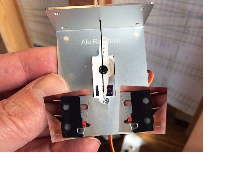 |
||
|
posted: 9 Sep 2018 14:26 from: madscientist click the date to link to this post click member name to view archived images |
Having installed both cobalts , soloneids , and servos , both with frog switching and frog juicers let me give u my perspectives The simplest form of existence is undoubtably cobalts etc. , easiest to install and integrated switches for feedback and frog switching , but it’s the dearest option Solenoids are the least sophisticated and unrealistic but simple and medium expensive Servos are cheap , very configurable and will do for points and signals whereas solenoids ate far too fierce , servos can be left active where they will exert considerable force holding the point over, or the signal can be removed in which case the gear train friction is more then enough ( the 5W RS solonoid mentioned would just break up points quite frankly ) I would agree with many , do not use micro switches with servos. Buy a controller that can switch relays Better yet join MERG and access their considerable range of servo kits Switch the relay from the servo controller , arranging micro switches on mechanical linkages etc is a mega pita especially with servos having programmable setting points . Servos despite requiring some “ roll your own work “ and the cheapest , Most realistic , and configurable option Now frog juicers are just brilliant and for dcc. If you can afford them , they are the best way to go , why because in dcc with ordinary frog switching when you go over an incorrect point in the trailing direction, you short put your whole dcc layout even if the switch blades would trail over , whereas With frog juicers everything keeps working , Complex Slips and scissors are a doddle Dave |
||
| Last edited on 9 Sep 2018 14:31 by madscientist |
|||
|
posted: 9 Sep 2018 14:39 from: Jim Guthrie
click the date to link to this post click member name to view archived images |
madscientist wrote: Now frog juicers are just brilliant and for dcc. If you can afford them , they are the best way to go , why because in dcc with ordinary frog switching when you go over an incorrect point in the trailing direction, you short put your whole dcc layout even if the switch blades would trail over , whereasI would agree with Dave - juicers get you round the complex interlocking on a DCC layout - like diamonds. 25_090935_300000000.jpg 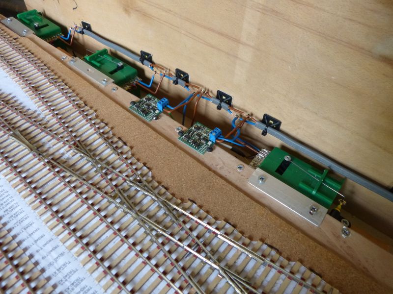 This is my US style switching layout with a diamond on the sidings and two Tam Valley mono juicers doing the business. Jim. |
||
|
posted: 9 Sep 2018 15:50 from: Martin Wynne
click the date to link to this post click member name to view archived images |
madscientist wrote:( the 5W RS solenoid mentioned would just break up points quite frankly )That depends on the design of linkage/escapement, the size of the air-damping plate, the inertia of the return system (such as a weighted lever), and of course the voltage used. The great advantage is that they are made of solid metal, not flimsy bits of plastic, and anyone can see how they work -- you just need some power and a switch, with not a chip in sight, all built out of Meccano and string. Or go for a hi-tech system: R8389550-01.jpg  http://uk.rs-online.com/web/p/pneumatic-roundline-cylinders/8389550/ Or slightly less hi-tech: 20ft.-air-release-8905-p.jpg  http://www.srb-photographic.co.uk/20ft-air-release-8905-p.asp p.s. I have had one of those for about 40 years. It is still good as new, and requires no batteries. Every time I use it, I see model railway possibilities. The stroke is an ample 15mm at constant force, and easily able to operate a set of points. air reservoir = old tyre under the baseboard. air valve = plastic syringe from pharmacy, drill hole in side of barrel, link to lever frame. Martin. |
||
|
posted: 9 Sep 2018 17:05 from: madscientist click the date to link to this post click member name to view archived images |
Martin , your just getting odder as well as older As Henry Ford said If I asked my customers , they’d have just said “faster horses” |
||
|
posted: 9 Sep 2018 17:48 from: Martin Wynne
click the date to link to this post click member name to view archived images |
madscientist wrote: As Henry Ford saidWhich don't need petrol, and don't drive on the wrong side of the road if they lose the GPS signal. Andrew is modelling the railway at a time when they employed thousands of horses, see: http://www.movietone.com/assets/BMN0624/wmv/BMN_92091_3.wmv Here is an interesting picture, from the above Movietone newsreel clip showing (allegedly?) the last working shunting horse on BR, filmed on 27th Feb 1967. Notice the catch points in the foreground -- the turnout rail is chaired on alternate timbers only. The only reason I can think for this is economy of chair castings. This may be a one-off for this location (Newmarket) or maybe typical of GER / LNER practice generally -- anyone know? vlcsnap-169994.png 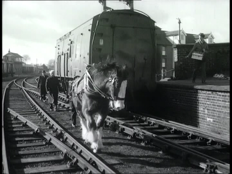 Picture linked from the PhotoBucket site: http://s193.photobucket.com/albums/z205/lamdelz/ regards, Martin. |
||
|
posted: 9 Sep 2018 18:20 from: Andrew Duncan
click the date to link to this post click member name to view archived images |
Hello Fraser Thanks for younr thoughts. I’ll try the control wire in the bottom arc and see if that improves things. Kind regards Andrew |
||
|
posted: 9 Sep 2018 18:31 from: Andrew Duncan
click the date to link to this post click member name to view archived images |
Hello again Fraser I should have read a bit further down the page! I’m pretty unsure about using micro switches now but the Dingo looks the business with a sliding tie bar of sorts which would stop the arc motion very neatly. But at present I need to decide on how to switch the crossing s if I’m not going to use the micro switches. Thanks again for your posts. Andrew |
||
|
posted: 9 Sep 2018 18:57 from: Andrew Duncan
click the date to link to this post click member name to view archived images |
Hello DaveThanks for your thoughts on things servo etc madscientist wrote: Having installed both cobalts , soloneids , and servos , both with frog switching and frog juicers let me give u my perspectivesI agree with your logic on solenoids and yes I like tortoise type motors, that are realistic and gentle on the mechanism. But I have found their switching to burn out though. I was a member of Merge a few years back and I’ve recently been very impressed by a couple of chaps I met at summer retreat at Missenden this summer. John Gowers ( edit:mixed out the s in John’s name) had a very impressive set up that he showed me briefly but I’m in no way an electronics man and I’m unsure of my ability’s to build electronics reliably. Having said that a friend did recommend the Merge “district cutouts” and they sounded reasonably easy to build so I will be investigating them. I also liked their hand held controllers. I currently use ZTC which although a bit old hat has excellent handhelds. The Merge one is the closest I’ve used to mine and if one day I had to change this would be my first choice. So far as the existing control boards are concerned I’m pretty well committed to Megapoints. They are very well thought through and well supported by Dave Fenton and not unreasonably priced. Wish they did a frog juicer also at a reasonable price as well! Yes I’ve very tempted by frog juicers as well for all the reasons you’ve just mentioned. Thanks again for your thoughts Kind regards Andrew |
||
| Last edited on 13 Sep 2018 07:38 by Andrew Duncan |
|||
|
posted: 9 Sep 2018 19:04 from: Andrew Duncan
click the date to link to this post click member name to view archived images |
Hello Jim That is some very neat trackwork and even neater wiring, well much neater then mine. I really should put more effort into that aspect of layout building. Thanks for your thoughts and the picture Kind regards Andrew |
||
|
posted: 9 Sep 2018 19:12 from: Martin Wynne
click the date to link to this post click member name to view archived images |
Andrew Duncan wrote:I like tortoise type motors, that are realistic and gentle on the mechanism. But I have found their switching to burn out though.Hi Andrew, There is a long topic on the Scalefour forum about the inadequacy and unreliability of the internal switching in Tortoise motors. Having dismantled one myself and seen the design, I would not use those switches for anything, especially not polarity switching of crossings. But if you use a Tortoise, the answer is simple. You can slave a relay straight across it with no more than a single diode, and the job is done. No additional wiring to the turnout, no microswitches to adjust. If you want the simplest and most reliable system, it would be hard to beat. No Meccano needed. Martin. |
||
|
posted: 9 Sep 2018 19:24 from: Andrew Duncan
click the date to link to this post click member name to view archived images |
Hello Nigel I’ll be interested to hear how you get on with Peco set up, should be good coming from that pedigree. I’m surprised to hear that your tortoises buzz. Maybe it’s my hearing but my old Maiden Newton layout has Tortoises and I can’t hear a thing. Mind you I’m using an old H&M one which is probably wheezing a bit these day so not many volts I suspect. At present I do certainly recommend Megapoints based on my experience of installing them and the back up, but perhaps I should be cautious until I’ve had it in daily use. Kind regards Andrew |
||
|
posted: 9 Sep 2018 19:35 from: Andrew Duncan
click the date to link to this post click member name to view archived images |
Martin Wynne wrote: Andrew Duncan wrote:Hello MartinI like tortoise type motors, that are realistic and gentle on the mechanism. But I have found their switching to burn out though.Hi Andrew, I wasn’t thinking of using either tortoises or Meccano, at least not unless all the above fails and I end up with egg on my face! Andrew |
||
|
posted: 9 Sep 2018 19:44 from: Martin Wynne
click the date to link to this post click member name to view archived images |
Andrew Duncan wrote:I wasn’t thinking of using either tortoises or Meccano, at least not unless all the above fails and I end up with egg on my face!Hi Andrew, Does that mean you have now found satisfactory answers to your problems in your message: topic 2547 - message 25595 cheers, Martin. |
||
|
posted: 9 Sep 2018 20:02 from: madscientist click the date to link to this post click member name to view archived images |
having reviewed both , I found the switching in cobalts to be more robust then tortoises | ||
|
posted: 9 Sep 2018 20:06 from: Andrew Duncan
click the date to link to this post click member name to view archived images |
Well a wee update 2787_091458_260000000.jpg 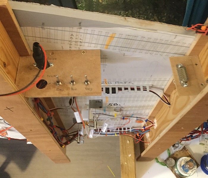 Yup as I said to Jim I do need to be neater in my approach to wiring. Anyway I’ve now finished splitting this board into 3 districts and compared to muddle I had before I now stand a sporting chance of finding electrical problems as I can now switch off each district separately wooow!!!! Other wise you can see the Megapoints plug and a hole where the track power din plug will go when it arrives from RS. Oh and the din plug for the Megapoints power. Food calls. Andrew |
||
|
posted: 9 Sep 2018 23:28 from: Andrew Duncan
click the date to link to this post click member name to view archived images |
Martin Wynne wrote: Andrew Duncan wrote:Hello MartinI wasn’t thinking of using either tortoises or Meccano, at least not unless all the above fails and I end up with egg on my face!Hi Andrew, Good question. Yes I think I probably have. 1. I’m going to dispense with the micro switches; too difficult to adjust reliably. 2. Try the Gaugemaster frog juicer as I have 3 and see how they do. 3. If they work well I’ll buy more to finish this board. 4. If they don’t I’ll replace them with Tam Valley juicers. Thanks to everyone who's let me know what their experiences have been. The feedback has been really helpful. Kind regards Andrew |
||
|
posted: 10 Sep 2018 10:00 from: Tony W
click the date to link to this post click member name to view archived images |
Hi Andrew. Can't believe how this thread has grown since my last comment at post 117, but glad Andrew has reached some conclusion. My only further comment regards the perceived problems with micro switches. I have used them on several occasions and once set up have generally performed reliably. I don’t use them for crossing polarity, but as limit switches. I have had failures with some on Green Street, but that was after 30 odd years use, so perhaps to be expected. Being a non DCC person, I have also learnt something as 'Frog juicers' were a mystery before. As an aside, I am custodian of the Nottingham Area Group's test track at Scaleforum this year, if anyone fancies a chat. Being a test track, the opportunity was taken to test various options on it. There are three crossovers, one being switched by Tortoise point motors, and the other two by servos, but using the Peco Smartswitch system for one, a MERG board for the other. The test track is not kept in the best of environments, it has to be said, being kept in an unheated storeroom at the the club. To date we have had one failure with a Tortoise point motor failing to switch a crossing polarity (traced to a contact failure within the motor). The Peco Smartswitch has performed impeccably, but one of the MERG controlled servos suffers badly from the twitches, which seems to decrease with use. PS I don't wish to hijack Andrews thread with comments about this, merely posting the above as observations. Regards Tony. |
||
| Last edited on 11 Sep 2018 09:39 by Tony W |
|||
|
posted: 11 Sep 2018 00:04 from: Andrew Duncan
click the date to link to this post click member name to view archived images |
Tony W wrote: Hi Andrew.Hello Tony Good to hear from you as always; I don’t believe there was a complete condemnation of micro switches in general but certainly in the application I was using them for they did seem a bit iffy. Quite apart from anything else the adjustment screws were difficult to get to and to see what was happening. They also had an inclination to push the servos back from whence they’d come although I think I might have overcome that problem? So as I strongly dislike stuff under the baseboard I thought a system that didn’t need adjustment was called for. Judging by his reference to the Geneva convention I’ve a feeling Martin probably agrees as well! I’m delighted that you’ll be at Scaleforum this year so I’ll pop along at some point. Not sure which day yet. Your experience with Tortoise switch gear is the same as mine and sounds like it’s common problem judging by the comments over the weekend on this thread. When you refer to solenoids for the other two examples, Merge and Peco, you then finish with a reference to servos? Were one of the boards controlling servos and the other solenoids, or have I just misread ....not unknown To complete your education on frog juicers, well actuall not a frog juicer, but an Autofrog( same idea but 2787_101847_530000000.jpg  uses a relay rather than solid state to change the polarity. The first picture shows the Autofrog first wiring up with a Wago plug stuck to the top as they don’t come with proper terminals, just three solder pads, hence the need for something to make them unpluggable! The next shows one installed on the layout. Not a neat job but I’ve got it colour coded and I think with the records I’ve now got I should be able to understand it in a few years time when all this is but a distant memory! 2787_101852_190000000.jpg 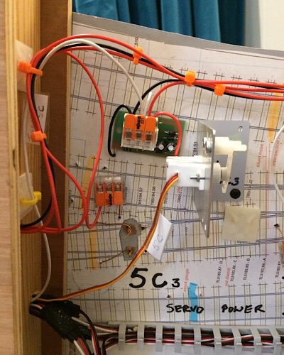 Kind regards Andrew |
||
|
posted: 11 Sep 2018 08:25 from: madscientist click the date to link to this post click member name to view archived images |
As an idea for future builds , why not create an electronics/ wiring duct , in our case ( club O gauge layout , based on the GWR direct line ) , designed by yours truelh , you can see the frog juicers n place , it’s much more crowed now with the Merg cobalt controls and other boards , but I don’t have a recent pic. The green boards are tam valley frog juicers the red ones are my own design DCC dropper connector boards |
||
| Attachment: attach_2742_2547_BFAC5314-300C-43E2-ADD7-15435F254590.jpeg 373 | |||
| Last edited on 11 Sep 2018 09:24 by madscientist |
|||
|
posted: 11 Sep 2018 09:50 from: Tony W
click the date to link to this post click member name to view archived images |
Andrew Duncan wrote: Tony W wrote:Hi Andrew.Hello Tony Hi Andrew. You have spotted my typo, it should of course have been servos in both instances. They wouldn't work with solenoids. I have corrected the original post now. I must admit that I am having similar thoughts regarding equipment under the baseboard re accessibility. Regards Tony. |
||
| Last edited on 11 Sep 2018 09:53 by Tony W |
|||
|
posted: 11 Sep 2018 14:03 from: Andrew Duncan
click the date to link to this post click member name to view archived images |
Tony Ah that explains it. Thank you! As to your further thoughts of what goes on top and what below, I’d be interested to hear how they go as time goes by. I’m considering going back to the way I construct my first version of Yeovil, in 00, where everything was on top of the boards and the jigsaw scenery covered most point motors and the wiring lay in trenches cut into the cork surface. In fact I’m increasingly masking myself why I didn’t do it this way on my current attempt! Part of the answer to that question is that I thought that by having all the baseboards removable for easy maintenance I’d not need every thing so accessible. I’m not sure now that that was such a wise decision? Kind regards Andrew |
||
|
posted: 11 Sep 2018 17:10 from: Tony W
click the date to link to this post click member name to view archived images |
Hi Andrew. With my previous layout Green Street, everything was underneath. My current thinking is to have the wiring underneath the layout, but the mechanical things such as point motors accessible from the top. You may have noticed that my straight scenic boards have a trackbed narrower than the subframes, the inner side spaces is where the point motors and control circuitry will go. Bare in mind that the electrics will be conventional DC, so there will be rather a lot of it. My approach for the fiddle yard will have to be different as there is too much track on top to do that, so it is most likely that the point motors will be mounted on the outside edge somewhere with (over scale) rod linkages to the blades. PS. When I say the outside edge, I mean the outside of the inner baseboard edge. Regards Tony. |
||
| Last edited on 12 Sep 2018 09:04 by Tony W |
|||
|
posted: 11 Sep 2018 19:11 from: Andrew Duncan
click the date to link to this post click member name to view archived images |
madscientist wrote: As an idea for future builds , why not create an electronics/ wiring duct , in our case ( club O gauge layout , based on the GWR direct line ) , designed by yours truelh , you can see the frog juicers n place , it’s much more crowed now with the Merg cobalt controls and other boards , but I don’t have a recent pic. The green boards are tam valley frog juicers the red ones are my own design DCC dropper connector boardsHello Dave Well funny you should suggest that, but that is not a million miles from what I have in mind (but not planned in detail...will I never learn?) for the front edge of my layout. There are some photos on page one of this thread which show the side of the base-baseboards. That is to say the baseboards that I've laid track on, sit on top of the base-baseboards. I think the picture will show you what I mean if you can find it. Its two thirds of the way done page one. What is different however to yours is that most of the wiring and the Megapoints control boards, as you know, are integral to track baseboards, whilst the lower supporting baseboards will just carry the buses for Track Power (split into 4 districts) and the Megapoints / Servo Power. I've done it this way to enable me to build and test complete sections of the layout independently in the comfort of our kitchen on one end of the kitchen table! I've a tolerant wife and family! Kind regards Andrew |
||
| Last edited on 11 Sep 2018 19:12 by Andrew Duncan |
|||
|
posted: 13 Sep 2018 07:47 from: Andrew Duncan
click the date to link to this post click member name to view archived images |
madscientist wrote: having reviewed both , I found the switching in cobalts to be more robust then tortoisesHello Dave That’s interesting, have you understood why? Like Martin I’ve had a Tortoise apart and although by looking I wouldn’t condemn them out of hand, my experience says there is something wrong with the design both from my experience and those of others. Have you taken one of the Cobalts apart to see why they seem better? Kind regards Andrew |
||
|
posted: 13 Sep 2018 12:40 from: Nigel Brown click the date to link to this post click member name to view archived images |
Andrew Duncan wrote: madscientist wrote:For the record, apart from the fact that I find them noisy, I've not had any problem with the switching on my tortoises. I do take trouble to make sure that when the tortoise is in mid travel the switch blades are also in mid position.having reviewed both , I found the switching in cobalts to be more robust then tortoisesHello Dave Nigel |
||
|
posted: 13 Sep 2018 13:47 from: Martin Wynne
click the date to link to this post click member name to view archived images |
There are 3 problems with the Tortoise switching: 1. plain copper is not a satisfactory contact material for other than very low currents. The Tortoise switches use phosphor-bronze wipers running along tracks of thin copper foil on the printed circuit board. If you can guarantee that you will never switch into a short-circuit condition, they are probably acceptable. That would happen for example if a loco or just a metal wheel is left bridging an isolation gap in the rails, with power on, and the points are then reversed against it. What then happens is that the full short-circuit current passes through the copper track as the wiper makes contact with it (until the short-circuit protection operates). The thin copper is very likely to be burnt and permanently damaged. Future operation of the contacts will be degraded, probably leading to a high-resistance contact instead of zero. 2. the actual design of the printed circuit board is very poor, with the tracks misaligned with the wipers. Andrew Jukes went so far as to have new circuit boards made for his Tortoise point motors. A full account of all this is at (2 pages): http://www.scalefour.org/forum/viewtopic.php?f=5&t=360 I believe the Tortoise circuit boards have since been through several design revisions by the manufacturers. That is indicative of the problem, and it is not easy to know if you are buying fresh stock. 3. contact pressure relies on the Tortoise motors being used in stall mode, i.e. the current remains on permanently in each position. As simple point motors they will operate the points just fine if you choose instead to switch the power off after movement is complete. This saves on power consumption and eliminates the slight buzzing noise from the stalled motors. However, if you do that, the back pressure from the points linkage causes the plastic drive arm to twist slightly, lifting the wipers from the copper tracks. Some have argued that this is not a fair criticism, because the Tortoise motors are intended to be used in stall mode, as indicated in their instructions. I would argue that it is indicative of the poor design of these switches, and limits a useful way of using the Tortoise point motors. One user I know, to operate his Tortoise motors, would connect the required one to the loco controller (DC) with a simple on-off switch, drive the points across visually using the loco controller, and then switch it off. It worked fine as a simple method of operating the points, needing no extra power supply or double-pole switches -- but failed because of the failure of the internal polarity switches to maintain contact with the power off. Martin. |
||
|
posted: 14 Sep 2018 08:45 from: madscientist click the date to link to this post click member name to view archived images |
Andrew , Martin has covered most of the issues I disassembled a recent tortoise and a cobalt omega ( I also traced the circuit diagram out for the cobalt ) As Martin says , tortoise is using bare copper , cobalt is gold tinned , the cobalt wiper is better engineered and the contact area is better As cobalts don’t use a special stall motor , merely a 5V motor that is powered via a comparatively high resistance feed , they then use a considerable gear train to reduce the motor speed to the arm speed , much more then the tortoise . This means that it’s not possible to mechanically force the actuator arm back from its stop position , so cobalts remain in position with the power present ( in stall ) or not , whereas with tortoises you can move the arm and hence if you remove power you loose pressure on the blades The main thing I don’t like about the cobalts is their power consumption in stall , upwards of 60mA stall current when the operating voltage is 12v , around 30mA when actually moving ( if you can arrange it , try and power cobalts from about 7v , anything above that is wasted in the internal zenner diodes ) . There is no audible buzz from the cobalts in powered stall Note these comments apply to the cobalt omega , not the IP And of course the cobalt is considerably smaller and has a lifetime warranty As a general comment , I do feel the switches are a weak design in both tortoise and cobalts and a belt and braces approach would be to use the point motor switch to switch an external relay, it I doubt many will bother All in all , I can’t see why anyone would bother on this side of the pond with tortoises quite frankly Dave |
||
| Last edited on 14 Sep 2018 08:51 by madscientist |
|||
|
posted: 14 Sep 2018 14:18 from: Andrew Duncan
click the date to link to this post click member name to view archived images |
Hello Dave Very clear succinct answer thank you. The only bit I didn’t understand was the reference to the two different types of Cobalt. Are you referring to the ordinary and DDC ready types? Thanks again Andrew |
||
|
posted: 15 Sep 2018 01:00 from: madscientist click the date to link to this post click member name to view archived images |
Andrew Duncan wrote: Hello DaveDCC concepts tend to love their own marketing speak , so you gets lots of it ! The Omega , is now the lowest spec , which is an improved version of the original ( the classic ) The Analog IP is basically a V2.0 version of the omega , with improved power supply range ,microprocessor control of the motor , and improved contacts , it’s easily worth the extra 2 quid or so, in fact I wonder why DCC concepts keep the omega in the range .( the difference is nearly nothing if you buy the 6 pack ) It also cuts off the motor at the end of the movement removing one of the big issues with the Omega , which is the high stall current , so unlike the Omega , the IP isn’t actually a stall type PM at all. The analog IP isn’t really any more “ digital ready “then the omega other then it can use DCC track power as a source of motor power The digital IP is DCC compatible |
||
| Last edited on 15 Sep 2018 01:09 by madscientist |
|||
|
posted: 15 Sep 2018 10:55 from: Andrew Duncan
click the date to link to this post click member name to view archived images |
Martin Wynne wrote: madscientist wrote:Martin and DaveAs Henry Ford saidWhich don't need petrol, and don't drive on the wrong side of the road if they lose the GPS signal. Now I’ve just caught up with you on this. When Dave first made the rather bold statement that you were getting not only older, but odder too boot, I was expecting verbal fisty cuffs or pistols at dawn, For some reason the meaning of Henry Ford quote eluded me. It took my French wife ( and it’s a well known fact that the French have no sense of humour) to explain to me what Dave was saying! Which made us both chuckle, me at both myself for not understanding it in the first place and at Dave’s wit. Your response brought further amusement at the kitchen table this morning. Thus disproving my previous statement about the French;a very entertaining way start a Saturday morning. Thanks to you both. Andew |
||
|
posted: 2 Oct 2018 23:33 from: Andrew Duncan
click the date to link to this post click member name to view archived images |
A little bit of progress on the electrics front. I’ve installed and tested with my ZTC 511 and it’s 5 amp power supply, three of the Gaugemaster Autofrogs and they seem very smooth in changing over the polarity. That is to say that running a loco dead slow over the crossing there doesn’t appear to be any hesitation as it hits the opposite polarity. Will they last the course, would it have been better to employ Tam Valley frog juicers, or should I have used relays as I did on the junction board? Only time and using them will tell. Here’s a picture or two of how i installed them. They come unwired and with just three solder pads on the underside, two to connect to the track power and one for the crossing itself. Not wanting to solder them in directly to the layout wiring I soldered three short wires from the pads which then go to a Chocolate Block strip double sided to the top of the Autofrog. I also double sided the Autofrog to the baseboard. Then I connected the three wires that had gone to the micro switch to the Chocolate Block strip on top of the Autofrog. And that is the job done really. If they fail then I can remove and replace them easily. To do this testing incidentally I’ve been trying to convert a Buffalo pannier to EM but it’s not running as well as it used to as an OO model. I thought it would be an easy conversion having outside frames all I need to do is to push the wheels out on on their axels and insert some fibre washers cut open just enough to allow their installation, extend the brake block lateral spacing and that would be it. It wasn’t quite that simple and as I say the running is quite up to scratch as yet. When I’ve got it sorted I’ll post a video of it working( very exciting! ) if some kind soul would would tell me how to put a video up? 2787_021815_260000000.jpg 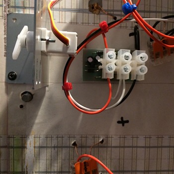 Sorry, just one picture as it turns out. Sometimes I think I’ve got the hang of resizing and uploading, then it all goes to pot and the computer shows who’s really in charge. This is the picture of the Autofrog installed, to state the obvious. Kind regards Andrew |
||
|
posted: 7 Oct 2018 23:05 from: Andrew Duncan
click the date to link to this post click member name to view archived images |
Hello Can anyone tell me how to upload a video preferably without involving YouTube as I don’t have an account with them. Kind regards Andrew |
||
|
posted: 8 Oct 2018 00:00 from: Martin Wynne
click the date to link to this post click member name to view archived images |
Andrew Duncan wrote: Hello Can anyone tell me how to upload a video preferably without involving YouTube as I don’t have an account with them.Hi Andrew, You need an account somewhere in order to upload a video. Unless it's a very short clip in a format supported as an attachment here. (SWF, GIF, MP4, FBR). 10MB max. YouTube is the easiest to use. If you don't want to create a YouTube account yourself, send it to me as an email attachment, and I will upload it to the Templot YouTube channel for you. (This means you will lose the option to edit it yourself.) Email success will depend on the file size. To see my email address, click my name on the left, and Profile. cheers, Martin. |
||
|
posted: 8 Oct 2018 23:37 from: Andrew Duncan
click the date to link to this post click member name to view archived images |
Martin Thanks for the offer of uploading a video. I did try to send one to you this evening but it didn’t go so I suspect the file size was the reason. I’ll get someone at work to show me what to do to use YouTube instead. Thanks again and I loved the photo of the style( I presume?) and church. Andrew |
||
|
posted: 9 Oct 2018 00:11 from: Martin Wynne
click the date to link to this post click member name to view archived images |
Hi Andrew, How big is the file? What type of file is it, e.g. MP4, MOV, WMV? If it's not too big I may be able to make a temporary change to the attachment settings to allow you to post it here. Yes, it's a stile, although not much used then as you can see -- that was a few years ago. It seems to have received some TLC since, this is Google's view 2 years ago: http://goo.gl/maps/3M7hbs6MwCr p.s. edit: just checked -- "a few years" turns out to be 16, that was June 2002. Where do they all go? cheers, Martin. |
||
|
posted: 9 Oct 2018 12:29 from: Andrew Duncan
click the date to link to this post click member name to view archived images |
Hello Martin Thanks for the offer of doing this. Its a MOV file and its about 40mb which is surprising as its only 39 seconds. Will the site accept a file of this size? Andrew |
||
|
posted: 9 Oct 2018 12:52 from: Martin Wynne
click the date to link to this post click member name to view archived images |
Andrew Duncan wrote:Will the site accept a file of this size?Hi Andrew, I don't know for sure, without getting advice from Jim. However, I have now added mov and MOV to the allowable types and temporarily increased the size limit to 80 million bytes (about 76MB). Give it a try, nothing to lose if it fails. cheers, Martin. |
||
|
posted: 9 Oct 2018 14:18 from: Andrew Duncan
click the date to link to this post click member name to view archived images |
Hello Martin No it’s said error invalid file. Tried three times. Unless you’ve any other ideas it’s back to some bright spark giving me a lesson in YouTube. Thanks for trying. Andrew |
||
|
posted: 9 Oct 2018 19:46 from: Andrew Duncan
click the date to link to this post click member name to view archived images |
[Edit] Well this is my first experience of uploading a video on YouTube and in Templot. Another string to my bow! Having said that it’s turned out a very narrow picture...? I’ve done a very rough conversion on this loco ( no rebuilt chassis I'm afraid) by just putting washers in the space created by the wider gauge but with its outside frames the narrow chassis isn’t too obvious. I haven’t finished the job as it’s missing it’s brake gear and lost a front sanding pipe in the struggle to push the back to back out to 16.5mm so that needs restoring as well. Kind regards Andrew |
||
|
posted: 9 Oct 2018 20:12 from: Martin Wynne
click the date to link to this post click member name to view archived images |
Thanks Andrew. You seem to have cracked YouTube. Looking good. cheers, Martin. |
||
|
posted: 10 Oct 2018 19:43 from: Martin Wynne
click the date to link to this post click member name to view archived images |
Andrew Duncan wrote:Having said that it’s turned out a very narrow picture...?Hi Andrew, It's narrow because you probably recorded it on a smartphone held upright? YouTube has then fitted it into its standard 16:9 landscape-format frame. If you had turned your phone on its side, it would probably have filled the frame better. If you do that, make sure it is not upside down -- the camera lens on the back should be at the top. Having said all that, YouTube is a law unto itself and not always predictable. p.s. if you are widening RTR wheels for EM, it is better to set 16.4mm back-to-back rather than 16.5mm (which is for EMGS wheels). cheers, Martin. |
||
|
posted: 10 Oct 2018 22:59 from: Andrew Duncan
click the date to link to this post click member name to view archived images |
Martin Wynne wrote: Andrew Duncan wrote:Hello Martin,Having said that it’s turned out a very narrow picture...?Hi Andrew Thanks for the tip on the phone. I'll try it out and let you know. As to the wheels they are Alan Gibson wheels that I have largely standardised on and the loco is one of his as well. A very nice kit with a mixture of white metal, nickel silver and brass which as a layout loco is good for me particularly on my old layout of Maiden Newton / Yeovil in 00 there were sharp curves and steep gradients and the weight of the white metal really helped the loco's pulling power. I've got three of them, one open cab as on the video, a closed backed cab, both of which are panniers(based in Yeovil in the early 20's and a third, yet to be built, in saddle tank format...gorgeous. So coming back to your thought on back to back I take it that 16.5 is correct for Gibson and the odd Ultrascale wheel? Kind regards Andrew |
||
| Last edited on 20 Oct 2018 20:56 by Andrew Duncan |
|||
|
posted: 21 Oct 2018 15:31 from: Andrew Duncan
click the date to link to this post click member name to view archived images |
Hello Below is a video of me testing out baseboard no 5 of YPMill and final fettling apart I’m pleased to say it worked pretty well straight away. You may well notice the loco jumping over some of the crossings but only the rear drivers appear effected. In this model that is the fixed wheel with the others compensated with traditional Sharman three point compensation. So I think it likely that the back to back on the rear drivers is a little tight. It may get a bit boring watching it go back and forth, back and forth but I wanted to demonstrate to myself that I could build track that worked and just in case it stops working between now and whenever it’s taken for a run next, that i did have it working on the 20th October 2018! So celebabrations t one side what I haven’t yet even really thought about is the signalling. I say not thought about, I really mean planned properly. I’ve got the Megapoints board installed ready to control them but I haven’t worked out how to build them. So far I’ve thought I’d mount them on a rectangular brass base plate with a copper or brass tube soldered to the underside that would go through a close fitting hole in the baseboard and also serve as the mount for the signal and the frame for the servo(s)to be held in. The benefit of this is to have a design that can just lift out of the baseboard without any fiddling underneath ( other than to unplug it electrically). Has anyone experience of building signals that unplug like this. Steve Hewitt is building beautiful signals over on RMweb but his require access underneath. I want to be able to set up a signal whilst still on the workbench. I’m sure I’ve seen somewhere an article on building them as I describe above but I can’t remember where it was or when. Can anyone point me in the right direction? Kind regards Andrew I’ll post the video separately |
||
|
posted: 21 Oct 2018 15:35 from: Andrew Duncan
click the date to link to this post click member name to view archived images |
Here it is... There is some sound but it’s towards the end of the video. H |
||
| Last edited on 21 Oct 2018 15:41 by Andrew Duncan |
|||
|
posted: 21 Oct 2018 16:22 from: Nigel Brown click the date to link to this post click member name to view archived images |
The slight bump going over some crossings just might be the crossing rather than the rear drivers. Might. Remember bumps involving the fixed axle are likely to be more noticeable than the rocking drivers. Like the idea for signals. I do something like that, maybe the way Steve Hewitt does it? I have a plasticard top plate (easily buried under ballast) and a plastruct tube glued vertically to it, which slots into a hole in the baseboard. The signal, including post and ladder, is built up from the top plate and is installed as a unit. But the servos are mounted and adjusted separately underneath the baseboard. The signal posts are plastic (Ratio or similar) which is why the base plate etc is plastic. Nigel |
||
|
posted: 21 Oct 2018 22:06 from: Andrew Duncan
click the date to link to this post click member name to view archived images |
Hello Nigel It’s interesting you using plastic for a plastic signal kit. As a matter of interest what diameter is the tube? For speed Ive wondered about using Ratio as they are pretty good models and a lot quicker than using MSE parts. Maybe I should try one out see how it looks. On the other hand I’ve used MSE and Springside in the past though and my concern is they may not be quite what I’m looking for. Needs some more thought. Thanks for ideas Kind regards Andrew |
||
|
posted: 22 Oct 2018 17:54 from: Nigel Brown click the date to link to this post click member name to view archived images |
Andrew Duncan wrote: Hello Nigel Can't find the tube I used but I'm pretty sure it was 10mm. This was for 3mm/ft scale. I used Ratio because at the time signal components such as final and lamps weren't readily available through the 3mm Society. So the signal post is slightly too thick, but not noticeable. I cut the post to the height I wanted. The final and lamp were trimmed to a more reasonable size using a scalpel. The arms and balance arms were from a 3mm scale fret from Worsley works. After connect the signal arm to the balance arm using nickel silver rod, another bit of rod went from the balance arm down through a small hole in the plasticard base and then through the tube down to the servo. If I was doing it now, I'd adopt a similar approach, but use finials and lamps from Modelu and a correct thickness plastic signal post from the 3mm Society. Nigel |
||
|
posted: 24 Oct 2018 22:19 from: Andrew Duncan
click the date to link to this post click member name to view archived images |
Nigel Brown wrote:Hello Nigel Thanks for the extra info on your signals. I must say I’d always thought I’d be building mine with a brass base but your use of plastic is making me wonder about it as an alternative , especially if I use Ratio. And this especially if I end up using the really mini servos which are about the size of my thumb nail to operate signals, as they might fit in a 10 - 15mm tube. And I may be able to just glue them in place as you’ll see in my next post with a standard servo. Needs some more thought and experimentation. Kind regards Andrew |
||
|
posted: 24 Oct 2018 23:04 from: Andrew Duncan
click the date to link to this post click member name to view archived images |
This is board no 3 at the southern or left hand end of the station. I’m xperimenting with this board in having as much as possible of the wiring and point controls on the surface rather then underneath. So there’s a servo stuck to a piece of plasticard ( to act as the base that I can screw to the baseboard) which I’m hoping to hide under the platforms and I’ve cut trenches through the cork for both the wire in a tube control from servo to turnout, and trenches for the wiring runs to the various sections / districts. When I’ve installed the wiring and turnout controls and “made good” then I’ll make a start on laying sleepers as I have previously. But this time I must remember to give the plan a wash of brown paint to kill the white. Without that any defect in the ballast shows up white like a sore thumb. At this stage I’m still thinking I’ll keep the servo wiring subterranean and again as far away from the traction power as possible. Not that I’ve experienced any problems ( so far) with board no5 when testing it out, but that was only one loco trundling up and down. 2787_241736_380000000.jpg 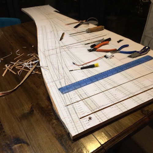 Time will tell on that one. Kind regards Andrew |
||
|
posted: 25 Oct 2018 03:49 from: Andrew Barrowman
click the date to link to this post click member name to view archived images |
Hi Andrew, Have you been able to try any serious train movements with the servos in operation? Andrew |
||
|
posted: 25 Oct 2018 10:13 from: Andrew Duncan
click the date to link to this post click member name to view archived images |
Andrew Barrowman wrote: Hi Andrew, Edited out the large white spacesHello Andrew Serious movements? I'm not sure what youre thinking of , but quite possibly not, just the Buffalo wandering up and down the no 5 board as in the video above. At present I don't have any other stock to test it out with as they are all still in 00 from my old Pen Mill / Maiden Newton layout! Andrew |
||
| Last edited on 25 Oct 2018 20:51 by Andrew Duncan |
|||
|
posted: 25 Oct 2018 19:14 from: Andrew Barrowman
click the date to link to this post click member name to view archived images |
Hi Andrew, The movements in that video are quite a good test. If you didn't see any strange servo behavior there's a good chance you won't have any problems. You might make the test conditions a bit more difficult if you can simulate intermittent connection between the wheels and rails. That tends to generate some pretty impressive bursts of interference. Cheers, Andy |
||
|
posted: 27 Oct 2018 23:54 from: Andrew Duncan
click the date to link to this post click member name to view archived images |
Andrew Barrowman wrote: Hi Andrew,Hello Andy I’ll give it a go when I next have a chance to get that board back on the table again. For the moment it onto board no 3. Talking of which I’ve just installed any surface wiring that needs to go down before I start laying sleepers, in other words any wires that go under sleepers. And I’ve been thinking how to join the operating wire from the servo to turnout tiebar and wondering how to get an omega loop or equivalent into the mix to prevent overdriving. By chance I came across Leeds City the Midland side on RM web. This one very impressive layout and John the builder surface mounts his servos as I’m doing and connects his operating wire in such a way as to give some slack. I’ll take a photo soon of my copy of his elegant solution. Here’s a photo of board 3 almost ready for sleeper laying to commence with the servos just laid in their approximate positions. They are under the platforms mostly or the road bridge. Kind regards Andrew 2787_271847_410000000.jpg 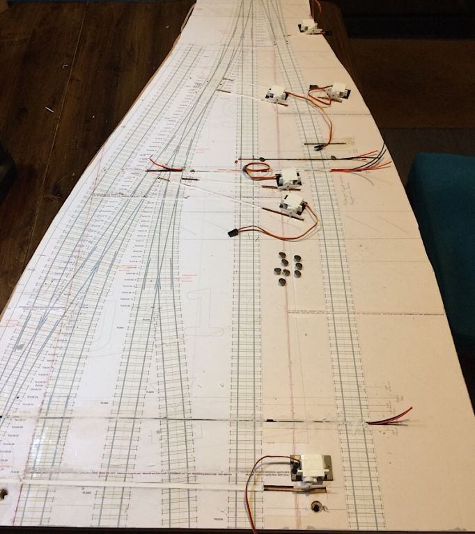 |
||
|
posted: 28 Oct 2018 00:40 from: Andrew Barrowman
click the date to link to this post click member name to view archived images |
Sounds good Andrew. I like the fact that you are mounting them "topside". BTW, the more slack you can put in the connection the better. That will increase the servo rotation which will reduce the tendency for the points to back-drive the servo. Ideally you'd like the servo to rotate through something like 120 degrees. I believe the latest version of the Megapoints controller stops sending pulses after a second or so. That reduces the probability of interference changing its position but it also means that the servo won't fight to maintain its position. Torque applied to the servo's horns can make it rotate, particularly if there is a lot of vibration. Increasing the angle of rotation reduces the torque. Cheers, Andy |
||
|
posted: 28 Oct 2018 06:17 from: Andrew Duncan
click the date to link to this post click member name to view archived images |
Andrew Barrowman wrote: Sounds good Andrew.Hello Andy Thanks for your encouragement and thoughts on servo drives, angles and so on. Without the microswitches that I originally had on the previous board (no5) and,as you know, subsequently removed, there shouldn’t be much if any inclination for my switches to back drive as they’re loose heeled. I use a 10BA nut soldered to the underside of the “hinge sleeper” and countersunk 10BA bolt with the head filed down to act as the loosely bolted fishplate. This photo should help explain what I mean I hope? Theoretically at least they will just blow around in the wind. There’s another photo or two on page one of this thread that shows a bit more. 2787_031702_460000000.jpg  And yes your quite tight about the Megapoints controllers. They no longer chatter to each other which is a considerable relief. The first board I built ( junction board no 2) and fitted the Megapoints board, has the earlier version and they talk incessantly. However Dave Fenton at Megapoints does an upgrade service,for a fiver I think, which I shall avail myself of at some point! So yes thanks again for the feedback, I’ll try to be as sloppy as possible. Not something I’ve ever had to a problem with.... Kind regards Andrew (Edited for spaces ) |
||
| Last edited on 28 Oct 2018 06:24 by Andrew Duncan |
|||
|
posted: 28 Oct 2018 07:03 from: Andrew Barrowman
click the date to link to this post click member name to view archived images |
"does an upgrade service,for a fiver" It's probably best if I don't say what I think about that on social media. |
||
|
posted: 28 Oct 2018 08:03 from: Andrew Duncan
click the date to link to this post click member name to view archived images |
Andrew Barrowman wrote: "does an upgrade service,for a fiver"Hello Andy Sounds like I’ve hit a sore point? That certainly wasn’t my intention. Let me know if I can clarify anything, as I’m unsure what it is that surprised you. Andrew |
||
|
posted: 28 Oct 2018 08:20 from: FraserSmith
click the date to link to this post click member name to view archived images |
I think it might be that charging to make the unit do what it really should have been doing already is a bit cheeky. Fraser |
||
|
posted: 28 Oct 2018 19:45 from: Andrew Duncan
click the date to link to this post click member name to view archived images |
FraserSmith wrote: I think it might be that charging to make the unit do what it really should have been doing already is a bit cheeky.Hello Fraser I have to admit to knowing very little about electronics but I thought it was standard practice for servo controllers to constantly check on the servo position and hence the chatter when it moved it back where it should be....or something like that? So should it have not chattered in the first place? Might this be a debatable point? What I’d say about Dave Fenton and his products are that they do what they say on the tin. Whenever I’ve had a question he’s answered it very fully and has been generally helpful. He also has a raft of easy to understand videos on his website which are very clear. Designed and made in this country. Megapoints have a lot to recommend them I think. So a fiver for an update....? Kind regards Andrew |
||
|
posted: 28 Oct 2018 20:58 from: Andrew Barrowman
click the date to link to this post click member name to view archived images |
Hi Andrew, Fraser interpreted my remark correctly Servos seem like a good idea, but there there are quite a few reasons why they are not a good idea on a model railway. But that's not to say you'll have any problems with them. Probably best to run a lot of tests before you get too far into the build. Cheers! Andy |
||
|
posted: 30 Oct 2018 00:11 from: Andrew Duncan
click the date to link to this post click member name to view archived images |
Hello Andy Let’s hope my initial tests are a good omen! Andrew |
||
| Last edited on 30 Oct 2018 00:12 by Andrew Duncan |
|||
|
posted: 30 Oct 2018 00:58 from: Andrew Duncan
click the date to link to this post click member name to view archived images |
Heres a little more progress on board no 3. Sleepers laid, barring the copper clad hinge sleepers for the loose heeled switches, the material for which I have just ordered. One the cats has walked off with one my eight servos, so I’m down to seven now, impressive maths. And if it wasn’t one of the cats or a human then I suppose it’ll be me having left it somewhere....but where? As an aside I went to Scaleforum last month with, amongst other intentions, of buying one of the Mk1 society lever frames. At the same time I wanted to see Howard Bolton’s 70 lever frame in the flesh and to see the new Mk2 to understand what “all the fuss” was about. Well in true Bolton style he has done a superb job of improving on the original which I had thought was a very good product( I built 5 of them for my old layout and thoroughly enjoyed the experience). So as you’ve probably guessed, despite my best intentions I came away with the etches for the Mk2. EDIT I realise as I reread this this morning, that I’ve left out my discussions with Howard. He’s a pretty persuasive fellow and it was only shear will power on my part that prevented me from not only buying the lever frame which I hadn’t planned on, but also the locking frame to go with it! Even as I write this I’m salivating at the thought, so maybe one day....? For the moment it was a narrow escape So this aside came about as I’ve just spent an enjoyable half hour reading the very full instructions that accompany the kit. I can’t wait to get started...but I think I’d better build some more track before I get distracted down the seductive etched kit road. Sorry about the angle of the photo 2787_291950_220000000.jpg 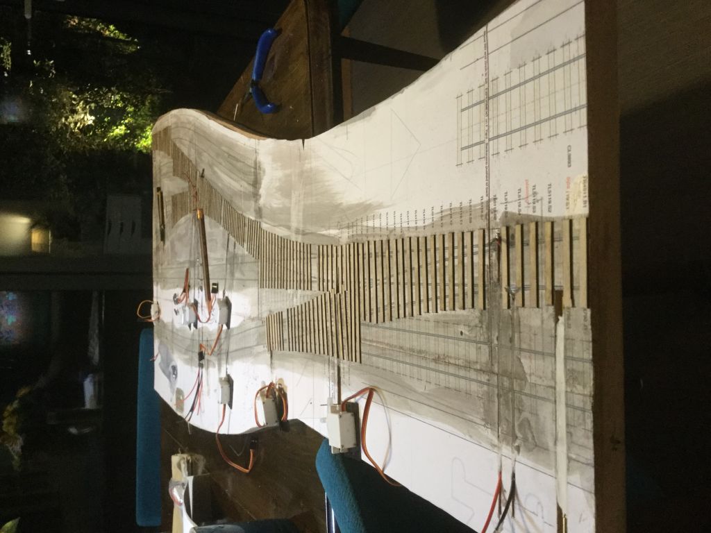 Before I go much further I must stick the track plan to the underside of the baseboard. Kind regards Andrew |
||
| Last edited on 30 Oct 2018 07:37 by Andrew Duncan |
|||
|
posted: 5 Nov 2018 23:17 from: Andrew Duncan
click the date to link to this post click member name to view archived images |
I’ve made a bit of progress on the hinges for the loose heeled switches over the last few days. This time I’ve used 1mm glass fibre copper clad for the timbers that provide the hinge points. The main reason is to allow me to provide a solid anchor point for the switch blades to hinge from. So I drill a couple of holes in the timber, solder two 10BA nuts to the underside and then screw counter sunk bolts through from the top. These then give a nice flat surface to solder the switch blade to. The copper timber thickness is a little too thick as the ply timbers are only 0.8mm thick, so I cut away the Templot plan to allow the copper to sit a little lower and this seems to work. Any variance can be taken up by adjusting the bolt up or down. I’m aware that this approach is a bit crude, but it seems to work and is less likely to fail electrically or mechanically I feel, than say springy wire. 2787_051729_420000000.jpg 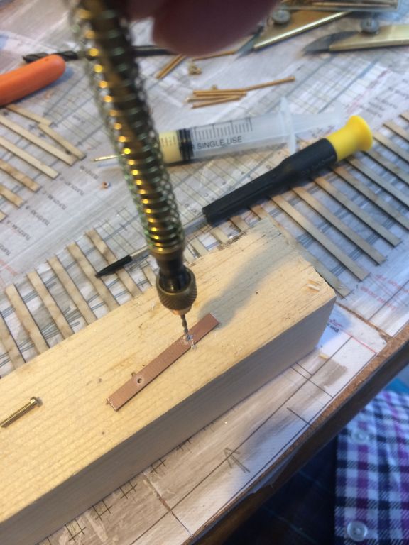 2787_051731_550000000.jpg 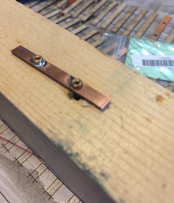 2787_051734_200000000.jpg 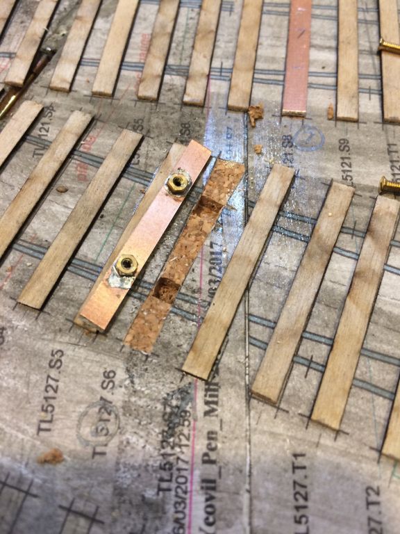 After the stage shown in the photo above i drill right through the baseboard to allow the bolts to protrude out at the bottom underneath the baseboard. And I gap the copper clad twice to be on the safe side, top and bottom. 2787_051733_000000000.jpg 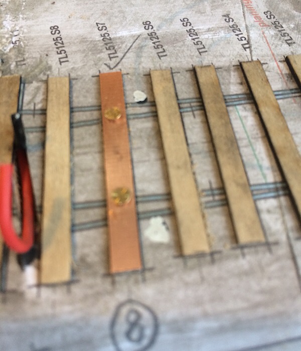 The other end of the bolts are used to provide the track power to the blades. The resulting blades have virtually no sideways resistance which makes them an easy drive for the servo. The next thing on my list is to produce 7 V’s That’s it for tonight Kind regards Andrew |
||
|
posted: 6 Nov 2018 01:37 from: Rob Manchester
click the date to link to this post click member name to view archived images |
That is good Andrew. Are you counter-sinking cheesehead bolts into the 'timber'? Can't quite see from the last pic as it a little blurred on my screen ( polite way of saying your depth of field is too small ). Could you sand the copperclad 'timber' thinner on one face to match the depth of the other timbers - you only need the copper to solder to on one side- unless you are also soldering the bolt heads to the copper. Look forward to future updates. Rob |
||
|
posted: 6 Nov 2018 09:51 from: Andrew Duncan
click the date to link to this post click member name to view archived images |
Rob Manchester wrote: That is good Andrew. Are you counter-sinking cheesehead bolts into the 'timber'? Can't quite see from the last pic as it a little blurred on my screen ( polite way of saying your depth of field is too small ). Hello Rob No I'm slightly countersinking counter sunk bolts but possibly the picture shows a cheese head(?) which i used to align the nut when soldering to the bottoe of the timber. so 10 out 10 for paying attention and an eye for detail. As a proper photographer your camera will doubtless have inumerable F stops with which to play. My Iphone seems to lack this, so my apologies for the lack focus. This would have my parents turning in their graves as they were both in the photgraphic trade most of their lives. Back in the 60's and 70's Dad had Pentax which was very swish at the time, and Mum a Rollei, Very confusing looking into the lense finder on that whilst at the same time putting your hand over it to shade the screen enough to seeing anything atall. but she loved it! Yes i could have filed the copper away on the top but i did that with the previous boards and it nearlty drove me crazy taking 0.8mm off evenly so when I came across the 1.06mm stuff I jumped at it. So no there no need for copper on the top as the head of the bolt is the hinge and needs to turn, albeit by not much! Thanks for the continued encouragement. Andrew |
||
|
posted: 17 Nov 2018 00:33 from: Andrew Duncan
click the date to link to this post click member name to view archived images |
A few years ago I made up jigs for all the Vs I’d need for the layout and so using three of these I’ve made up 7 of them for the turnouts on this board I’ve then assembled three of them(so far) on a duplicate plan. On the plan I first superglued some strips of brass about 2mm wide and 0.5mm thick below where the timbers support crossing and closure rails. 2787_111848_020000000.jpg 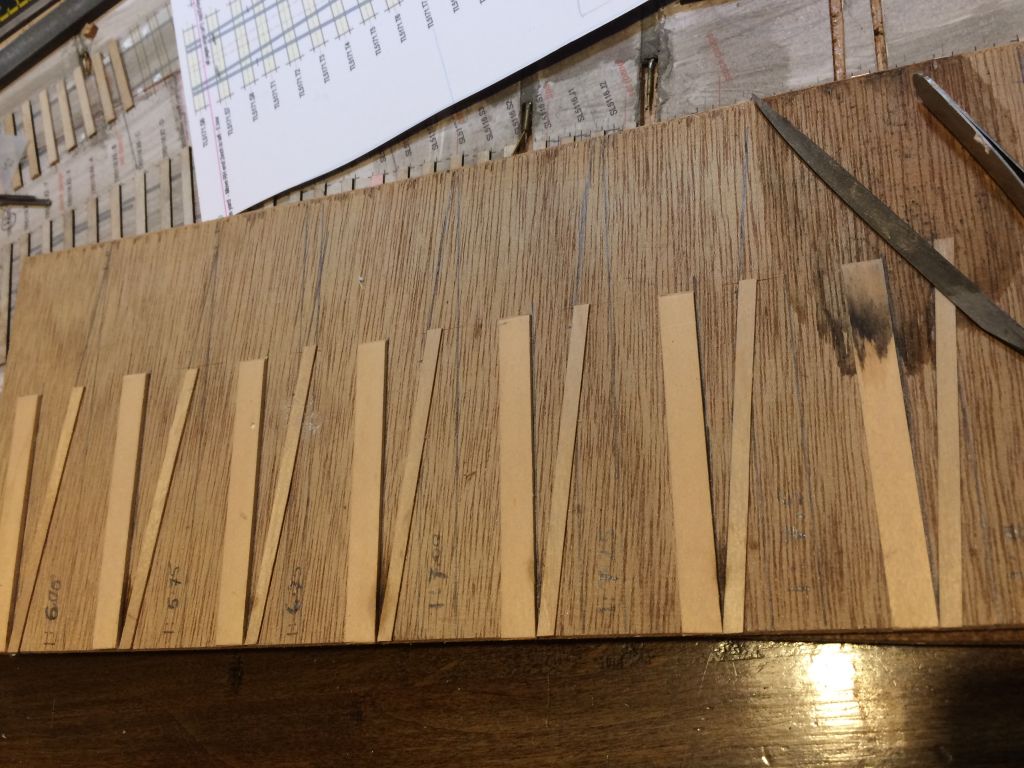 I hope this photo shows what I mean. Here you can see the brass strips supporting the Vs, the wing rails and closure rails. And here you can also see the two 1.0mm spacers I use to set the flange way gaps through the crossing. They are very shallow in height and so a bit fiddly but, I find the benefit of being able to see exactly what’s going on, on either side of the gauge pays dividends for my slightly haphazard way of working. I got the idea from Tony Gee at Missenden last summer. 2787_122002_280000000.jpg 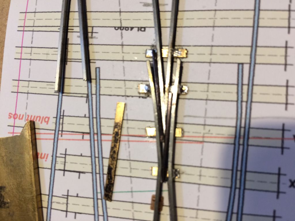 Having then soldered up the assembly I put a sharp knife under the brass strips to lift them off the temporary plan and give them thorough scrub in the sink. I’m using steel rail so being able to get rid of all flux deposits it an advantage. 2787_161843_570000000.jpg 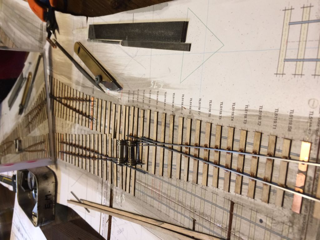 Having dried them they’re then ready to glue in place on the layout, having first trimmed the excess brass strip to length flush up against the side of the rail. That’s about it for now. Kind regards Andrew |
||
|
posted: 17 Nov 2018 18:27 from: Rob Manchester
click the date to link to this post click member name to view archived images |
Andrew, Thanks for the 'proper photographer' comment although I think 'photographic equipment geek' would be more appropriate If I wanted to remove the copper on one side of a timer I would just rub it up and down on wet'n dry paper until it was gone. Just an idea. The methods involved in assembling the crossings are very similar to what I use although I often put some of the brass strips between the timbers so you can use normal chairs functionally. Takes a bit of planning though..... Rob |
||
|
posted: 18 Nov 2018 00:29 from: Andrew Duncan
click the date to link to this post click member name to view archived images |
Rob Manchester wrote: Andrew, Hello Rob When you say that you sometimes put brass strips between the timbers, how do you stop them showing up? Having written this question to you, I suppose within the confines of the crossing area they might not show as rails are so close together? I may give your wet and dry technique a go with hinge sleepers on the next baseboard. My iPhone is a 5 incidentally, so I imagine the digital sensor is probably smaller still, but it doesn’t seem to have done the trick in my snapshots! Kind regards Andrew |
||
| Last edited on 18 Nov 2018 00:30 by Andrew Duncan |
|||
|
posted: 18 Nov 2018 08:00 from: Hayfield
click the date to link to this post click member name to view archived images |
if using plastic timbers I am happy using the plastic chairs functionally using prebuilt Vees not common crossing assemblies. I use the Exactoscale products (E4CH 502A common crossing and E4CH 403A 0.8 check rail chairs) mostly as designed following the Exactoscale common crossing chair guide with these exceptions :- 1/ A&B timber positions I use either slide chair bases or 0.5 copperclad to support the tip of the Vee 2/ B timber position I use check chairs on the wing rails with one outer chair part removed 3/ X chair position I either use the centre part of a check chair or a centre part of one of the block chairs on the common crossing fret the correct size to fill the gap 4/ The gap between the wingrails and Vee in the A position can be filled with check rail chair centres if required I have found this method totally reliable with plastic timbers, but would hesitate with ply timbers owing to the strength of bond between ply & plastic You could switch the X & B timbers for either plastic of copperclad timbers, with the latter substitute plastic chairs with cast metal half chairs |
||
|
posted: 18 Nov 2018 12:14 from: Nigel Brown click the date to link to this post click member name to view archived images |
Hayfield wrote: if using plastic timbers I am happy using the plastic chairs functionally using prebuilt Vees not common crossing assemblies. I use the Exactoscale products (E4CH 502A common crossing and E4CH 403A 0.8 check rail chairs) mostly as designed following the Exactoscale common crossing chair guide with these exceptions :- You could switch the X & B timbers for either plastic of copperclad timbers, with the latter substitute plastic chairs with cast metal half chairsHi Hayfield I used a similar system on my 3mm'ft layout. Only 3-bolt chairs for plain track plus slide chairs were available at the time. Everything else was built by carving those chairs as necessary. I used Plastruct strip for sleepers/timbers, and Plastic Weld to fit everything together. The result is as solid as a rock, but things can be adjusted by sliding a thin blade between chair and sleepers/timbers. However, as one might expect, chairs and sleepers need to be of a compatible plastic. The 3mm Society fairly recently introduced its own chairs, but no sleepering or timbering to go with it. These chairs don't work well with Plastic Weld, so Plastruct strip is no good. I'm told Butanone, which I can't stand, will work with the chairs, I suspect Mekpak will as well; neither works well with Plastruct. It's been suggested that Evergreen strip is a different plastic from Plastruct and should work, but I've yet to try it out. Obviously in 4mm the Exactoscale or C&L products should work together OK; I mention the above in case someone is working in unusual scales. The 3mm Society approach seems to be based on the assumption that everyone will use ply sleepers, something I've not found satisfactory. Nigel |
||
|
posted: 18 Nov 2018 21:18 from: Rob Manchester
click the date to link to this post click member name to view archived images |
Hello Andrew, Sorry. I should have been more specific in my suggestion concerning brass strips between the timbers - it would only usually be done like this if I were modelling a location where the ballast or other surface was high enough to at least partially hide the brass. As John ( Hayfield ) has noted the bond strength with chairs to plastic sleepers is excellent and many people just build crossings without any additional support. Chair to timber joint strength isn't quite as robust especially if the timbers have been pre stained. The ip5 sensor is a little smaller than later models but I wouldn't worry about it as the difference is very small. I bet the camera is better than my Huawei/Tesco/Android Rob |
||
|
posted: 20 Nov 2018 00:06 from: Andrew Duncan
click the date to link to this post click member name to view archived images |
Rob Manchester wrote: Hello Andrew,Hello Rob No apology necessary and thanks for your various explanations. I’m glad my iPhone isn’t beyond redemption! In fact I keep on being quite impressed by its abilities particularly at taking close ups of railway related stuff and think the definition isn’t at all bad considering the minute size of the lens and that it’s not its main function. But maybe thats like comparing a clockwork tinplate with P4! Kind regards Andrew |
||
|
posted: 9 Dec 2018 00:21 from: Andrew Duncan
click the date to link to this post click member name to view archived images |
A bit of an update. On Tony Wilkins thread on the Scalefour Society’s Eforum I came across Howard Bolton’s reference to a rather nifty and simple to construct tiebar arrangement that Mike Norris uses on his very large layout which he describes in Scalefour News 181 (early 2013). They are a simple arrangement with the copper paxolin moving sleeper idea turned literally through 90 degrees so that it’s lies on edge. So far Ive made up three of these and apart from a mild concern that it may suffer from metal fatigue it’s no more work to make and install than my current rather ugly efforts I hope the photos will show what I’m describing better than my words. This photo shows the switches awaiting the new tie-bar. 2787_081903_520000000.jpg 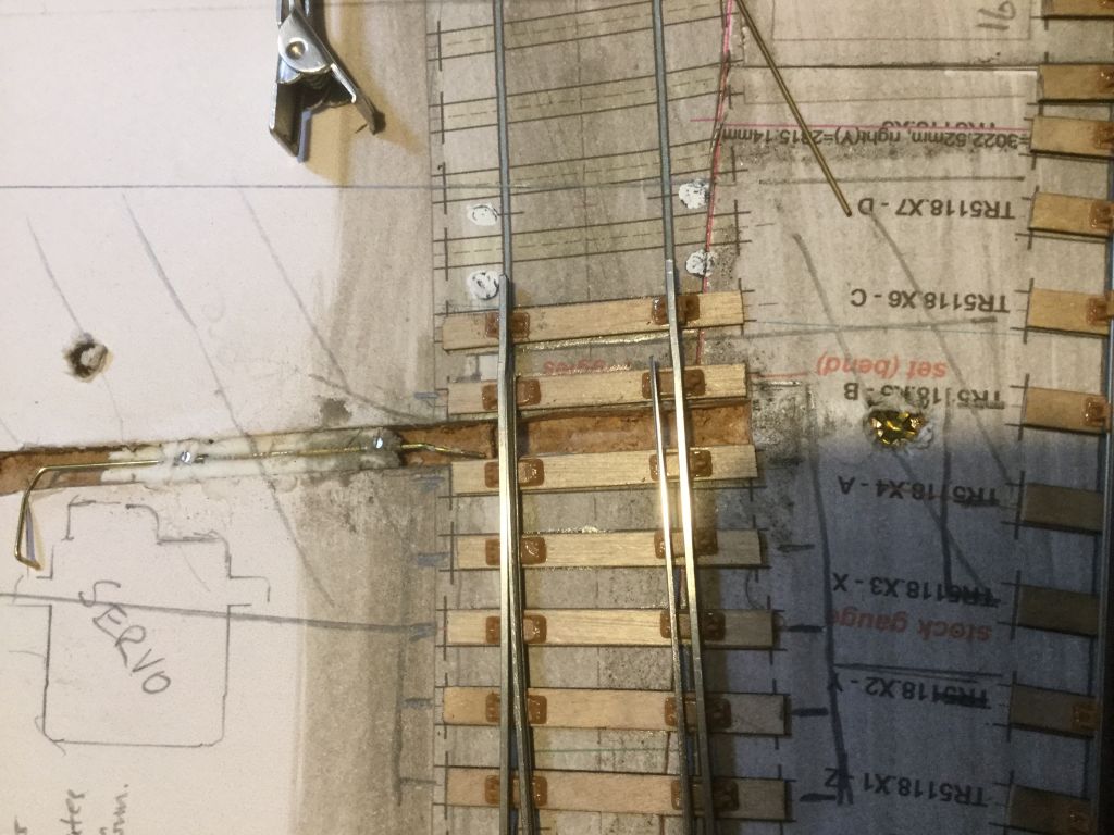 And this one shows it installed. Bit difficult to see, but that of course is it’s charm. 2787_081920_250000000.jpg 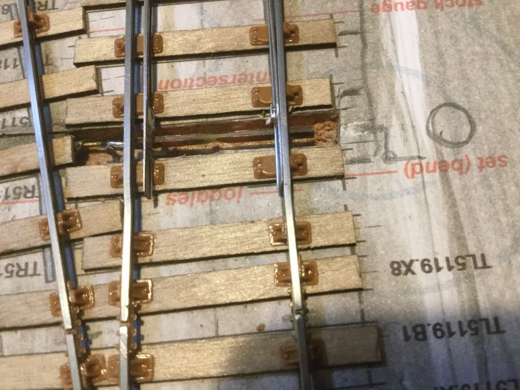 I’m using fibreglass covered copper gapped on both sides which I feel is a bit stronger and finer/thinner than the copper paxolin sleeper material I use for the loose heeled hinge sleepers. Andrew |
||
| Last edited on 9 Dec 2018 00:23 by Andrew Duncan |
|||
|
posted: 9 Dec 2018 01:27 from: Andrew Barrowman
click the date to link to this post click member name to view archived images |
Andrew Duncan wrote: A bit of an update.Hi Andrew, In my experience with that arrangement the solder joints will fail. PCB material is just not flexible enough. There's a trick that lets you substitute a vertical phosphor bronze strip instead. Form a piece of PB into a right angle and solder it to a double-sided FR4 tie-bar. Now grind away most of the tie-bar and the horizontal part of the PB. You will be left with a very flexible PB tie-bar with two insulated pads to solder the switch rails to. Somewhere there is a photo showing this in a bit more detail. I'll post it if I can ever find it again Cheers, Andy |
||
|
posted: 9 Dec 2018 08:15 from: Andrew Duncan
click the date to link to this post click member name to view archived images |
Hello Andy Thanks for your reply and yes I agree with you it would be very fragile if it were perhaps as I may have described . So my apologies for not taking more time to do a proper job of explaining how I did it. I made up a little jig to enable me to driI two holes just over 15mm apart in the centre of tie-bar material. I then soldered in a separate (Edit to correct the dimension) 0.45mm wire into each hole ( equivalent to the pad you suggested) the business end of which is bent through ninety degrees( once vertically and once horizontally) which ends up with 3 or 4mm of wire lieing horizontal. And this wire can be soldered into the web of the rail. So it’s the wire that takes the strain and my concern is that this may “give” in time. However I believe that a largish number have been in use now over some years on Mikes layout. If you have access to the description in Scalefour news 181 then all will be clear. If not then I’ll take picture or two of it later which will help make things clearer. Kind regards Andrew edit PS I realise looking at both photos of two different switches that they don’t appear to be a snug fit in the joggle and this important for reliable running so I shall be going back to check on this and do some “acing” on both the fit and the blade shape on the running surface. |
||
| Last edited on 7 Jan 2019 23:31 by Andrew Duncan |
|||
|
posted: 9 Dec 2018 08:56 from: Stephen Freeman
click the date to link to this post click member name to view archived images |
Not too dissimilar to the AMBIS solution. Being "old-fashioned" I also believe in the belt and braces approach to common crossings. A couple of small points though. I think the blades overhang the slide chairs a bit too much and have you considered replacing the slide chairs with the Modelu ones? | ||
|
posted: 9 Dec 2018 09:31 from: JFS
click the date to link to this post click member name to view archived images |
Since my name is mentioned in Andrew's post, I feel I ought to contribute to correct a few mis-impressions. Firstly I wonder if either Stephen or Andy have actually read the original article before offering comment on the design? Andy, you say you have "experience of this arrangement" yet you seem to miss the point that it is the design of the wires which creates the flexibility NOT the PCB. I hereby accuse you of jumping to assumption!!! Stephen, perhaps you can describe to me in what way this is similar to the Ambis design? If you refer to the original magazine to which Andrew refers, you will see (coincidentally) a lengthy article by myself decsribing my use of the Ambis design and I specifically mention NOT to use PCB as it is not flexible enough (I use GRE and bonded joints). So I would rather say that Mikes design is at exactly the opposite end of the design spectrum to the Ambis design. Finally - Andrew - severe smacked wrist for you. Why on earth have you chosen to gap the PCB like that rather than the way Mike designed it? You have the gap on both sides opposite each other (creating a stress raiser) whereas Mike has two gaps on one side and single one on the other so that they reinforce each other. And you have gone well into the "bone" beyond the "meat" beyond the fat! The trouble with all good designs is that the brilliance lies in the subtle detail which the critics can't be @rs*d to comprehend... |
||
|
posted: 9 Dec 2018 12:52 from: Stephen Freeman
click the date to link to this post click member name to view archived images |
At the moment I must admit that I am failing to see the difference between GRE and GRE copperclad suitably gapped (yes it is possible though difficult to do it without affecting the GRE) other than the advantage of being able to solder rather than rely on a glued joint. Flexibility of Copperclad depends largely on the type of Copperclad involved. 1mm or 1.6mm is far too thick of course to impart any flexibility. Alan Austin suggests 0.5mm for 7mm scale and 0.25mm for 4mm scale. Andy's method is different as it is not intended to look like a stretcher bar as it is to be hidden as much as possible with a suitably cosmetic stretcher bar to be added. Howard is right about the copperclad gaps of course. Yes I have read the article, still don't like the idea of relying on glued joints and of course Alan Austin has since changed the design of his fixings. |
||
| Last edited on 9 Dec 2018 13:11 by Stephen Freeman |
|||
|
posted: 9 Dec 2018 13:45 from: Martin Wynne
click the date to link to this post click member name to view archived images |
Copied from a post of mine on RMweb: ________________________________ In the olden days (1970s) I manufactured tie-bars based on these methods as part of my Kit-Trak range. The pin is free to rotate in the bar as the points move over, so the design is entirely stress-free. The switch rail is free to take up the correct prototypical curve in the open position, for both flexible and loose-heel switches. The bar runs directly under the stock rail, holding the switch blade down on the slide chair and preventing the tip from kicking up under traffic (an important function of prototype stretcher bars, especially on loose-heel switches). The tie-bar was unclad 1/32" fibreglass, 3mm wide. The 1mm dia. pins were turned from nickel-silver or brass, having a thin head below the tie-bar and a small profiled groove to receive the foot of the switch blade for soldering. Anyone with a lathe would be able to replicate that method. I will try to find the pin drawing. It produced a reliable and unobtrusive blade fixing. The construction depth below the stock rails is less than the timber/chair/rivet depth, providing a clearance in the event any particles of ballast get underneath it. Hi Gordon, I could find only a scruffy sketch from 1975, so here's a new sketch. It's a good few years since I made any of these pins. They are quite quick to do, the groove doesn't have to be too precise, it gets filled with solder (stiffening the pin in the process). I used a form tool to make these pins in production: 2_060951_320000000.png 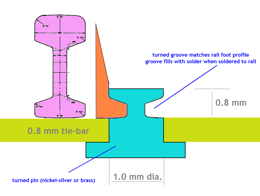 _______________________ These tie-bars were used on Adavoyle Junction (P4 21mm gauge) and gave no trouble during the 20 years it was on the exhibition circuit: ad7.jpg 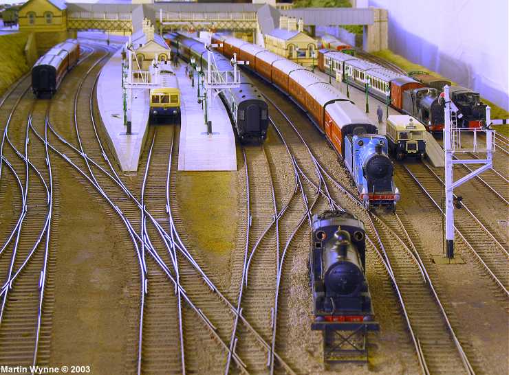 They are unobtrusive and can be further hidden by sprinkling a bit of ballast on top of them, and adding dummy prototype stretcher bars (we never got round to doing that). Assembly is very easy, because the switch blade foot locates into the pin dry, with a bit of packing from the stock rail. Then some phos flux, a dab with a loaded soldering iron, and you are done. regards, Martin. |
||
|
posted: 9 Dec 2018 20:24 from: Andrew Barrowman
click the date to link to this post click member name to view archived images |
Couldn't find the photo so I made this example to help explain what I was wittering on about. Strip of 0.031" double sided FR-4 and piece of PB strip folded down the middle. 2983_091517_220000000.jpg 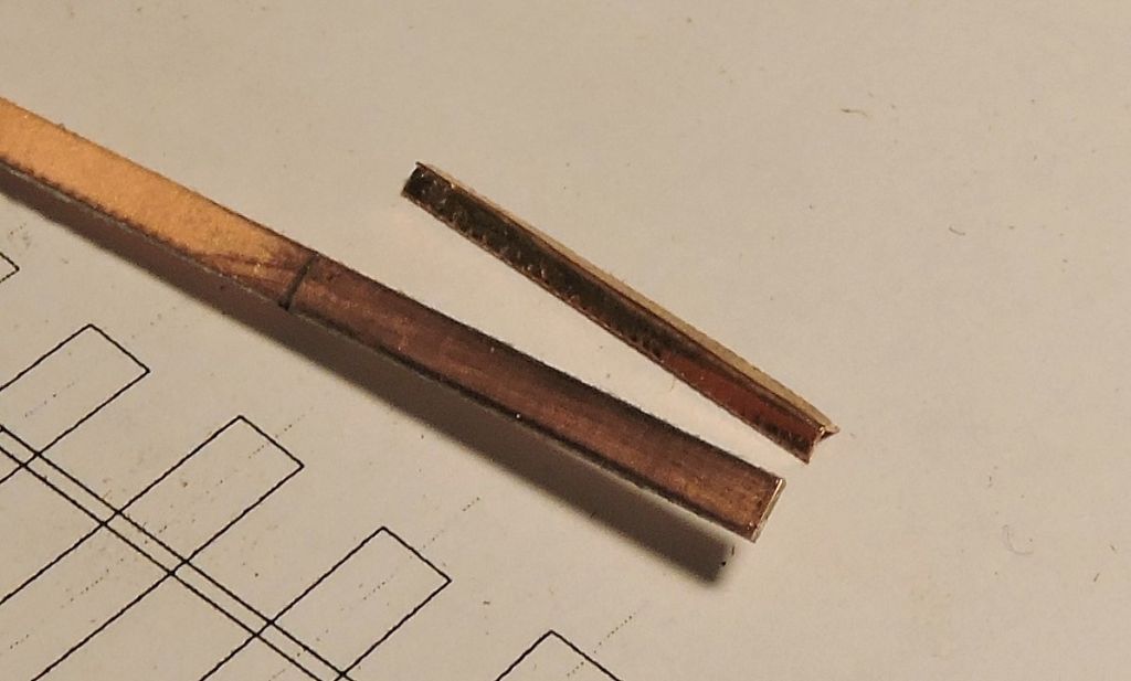 Solder the PB to the FR-4 then grind away the bits you don't want. 2983_091520_080000000.jpg 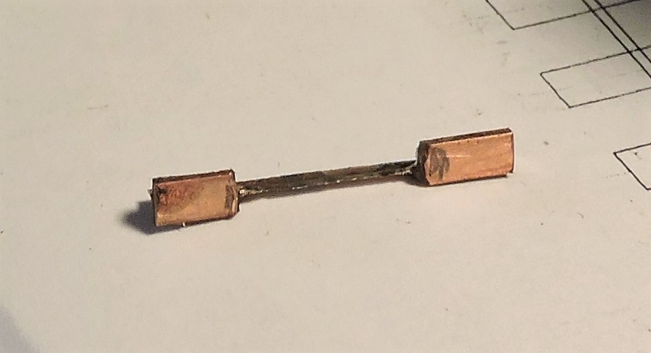 I've no idea if this is any simpler or better than any other method |
||
|
posted: 9 Dec 2018 22:07 from: Andrew Duncan
click the date to link to this post click member name to view archived images |
JFS wrote: Since my name is mentioned in Andrew's post, I feel I ought to contribute to correct a few mis-impressions. Firstly I wonder if either Stephen or Andy have actually read the original article before offering comment on the design? Andy, you say you have "experience of this arrangement" yet you seem to miss the point that it is the design of the wires which creates the flexibility NOT the PCB. I hereby accuse you of jumping to assumption!!! Stephen, perhaps you can describe to me in what way this is similar to the Ambis design? If you refer to the original magazine to which Andrew refers, you will see (coincidentally) a lengthy article by myself decsribing my use of the Ambis design and I specifically mention NOT to use PCB as it is not flexible enough (I use GRE and bonded joints). So I would rather say that Mikes design is at exactly the opposite end of the design spectrum to the Ambis design.Hello Howard Guilty as charged...! but not out of carelessness or don’t give a damn, just an enthusiast desire to get on try it! I shall now pay some attention to how I gap! Kind regards Andrew |
||
|
posted: 9 Dec 2018 22:12 from: Andrew Duncan
click the date to link to this post click member name to view archived images |
Stephen Freeman wrote: Not too dissimilar to the AMBIS solution. Being "old-fashioned" I also believe in the belt and braces approach to common crossings. A couple of small points though. I think the blades overhang the slide chairs a bit too much and have you considered replacing the slide chairs with the Modelu ones?Hello Stephen Yup I think you’re correct about the blade length. What do you feel is the benefit of the Modelu slide chairs ? Andrew |
||
|
posted: 9 Dec 2018 22:25 from: Andrew Duncan
click the date to link to this post click member name to view archived images |
Andi Thanks for going to the trouble to make one to explain your approach which I now understand. I shall stick to the Norris version, suitably chastened by my lack of observation and now have two cuts one side, and one tother Kind regards Andrew |
||
|
posted: 10 Dec 2018 07:36 from: Stephen Freeman
click the date to link to this post click member name to view archived images |
I'll try again - something weird going on with the edit option - Modelu 2 bolt sliderail chair - from a scan of GWR slide rail chair Exactoscale/C&L - wrong shape and too many bolts. C&L have an almost accurate version in 7mm scale - missing representation of bolt securing chair to rail. Link to Modelu sliderail chair Stephen Freeman wrote:Not too dissimilar to the AMBIS solution. Being "old-fashioned" I also believe in the belt and braces approach to common crossings. A couple of small points though. I think the blades overhang the slide chairs a bit too much and have you considered replacing the slide chairs with the Modelu ones?Hello Stephen Yup I think you’re correct about the blade length. What do you feel is the benefit of the Modelu slide chairs ? |
||
| Last edited on 10 Dec 2018 13:49 by Stephen Freeman |
|||
|
posted: 10 Dec 2018 13:07 from: JFS
click the date to link to this post click member name to view archived images |
Andrew Duncan wrote: Hello Howard It will all seem so much easier once your sore wrists are better!! Good luck and Best Wishes, Howard |
||
|
posted: 12 Dec 2018 22:26 from: Andrew Duncan
click the date to link to this post click member name to view archived images |
JFS wrote: Andrew Duncan wrote:Hello HowardHello Howard Thank you I’m sure it will! I had another look at the article to try understand why I missed this clever design feature ( two cuts one side one the other) and couldn’t see any reference to it. Are you sure it isn’t an improvement that you made when you made some. It seems to be quite clear in the article that Mike has gapped as I did, opposite each other...? Have I misunderstood your meaning somehow? Kind regards Andrew |
||
|
posted: 24 Dec 2018 03:44 from: Andrew Duncan
click the date to link to this post click member name to view archived images |
Hello Everyone I’ve not made much progress in the last few weeks electrics apart. But on this subject I’ve installed the Megapoints board for controlling the turnout and signal servos and here’s there’s been an interesting development. But before I get to that I’ve also decided to use the Megapoints relay board, as I had one in stock, to change the polarity of the crossings as previously did on the junction board. So in addition to the Servo control board there’s the interface board for the relays and the two relay boards themselves. Anyway back to signal operation. I think I mentioned a little while ago a chap, John over on RMWeb, who’s building an impressive layout of Leeds City the Midland side in EM. I noticed having read through 30 odd pages logging his progress since late 2012, that he’d developed a very neat MDF frame which holds the servos and off which he’d constructed his signals. After some brief communication he kindly sent me three examples to play with. I have since made up all three frames and actually put together a Home starter signal (one of Ratio almost readymade ones for speed) on one of the three frames. An exercise that took remarkably little time including installing the servo itself and linking it up to the Megapoints board. And it works and as with any Megapoints install it’s a doddle to adjust. Incidentally I chose a very small digital servo (from Hobbyking) for this purpose as I read somewhere that they didn’t move on start up (so less likelyhood of damage to the signal mechanism) and sure enough it remained stoically silent throughout the whole process. Makes me wonder if I could use them as an alternative to the bigger 9gm servos for turnouts where space is tight and where servos are mounted topside. I’ve included a couple of photos of the install which at present is just Bluetacked to edge of the baseboard. To give a better idea of how small this assembly is, the baseboard is 12mm thick MDF which I hope will give you an idea of how neat and small the servo frame is and indeed how small the servos themselves are. This shows the double width frame that could take two servos side by side 2787_232248_070000000.jpg 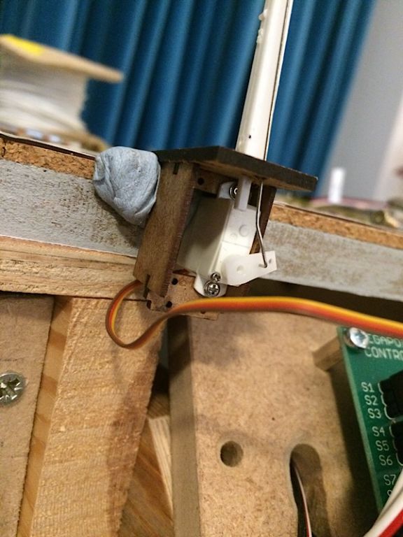 And this one an overall view of this rather hastily assembled experiment. Apologies if your a signal buff and this slightly gung-ho approach offends! 2787_232255_010000000.jpg 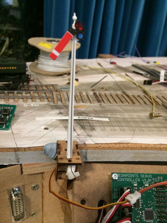 This is all very exciting stuff as I was quite concerned about how I was going to get reliable easily adjusted signals constructed that plugged in from above the baseboard, and this design of John’s has made this a great deal easier and therefore more achievable. A happy and peaceful Christmas to you and thank you to all of you who have read about my goings on at the end of the dining room table and to those who have replied with thoughts and ideas over the last year. I find it surprising and really encouraging. Thanks. Kind regards Andrew PS MartinAs this is wandering off the topic of track building would you prefer that I had posted to Share & Show? |
||
| Last edited on 24 Dec 2018 04:59 by Andrew Duncan |
|||
|
posted: 24 Dec 2018 04:54 from: Andrew Duncan
click the date to link to this post click member name to view archived images |
And finally to add a little more clarity to the previous post here are a couple more shots. This one shows the frame detail a little more clearly of the double width servo frame. 2787_232333_450000000.jpg 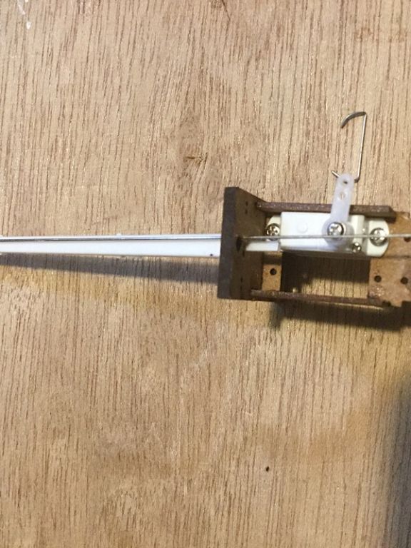 And here’s the same thing in single width. On this one I’ve left it full length with two servos installed but as you can see it will take three and the same goes for the double width one above which if left at full length will take 6 servos. The question I ask myself then is do I have the skills to make the signal that these would drive...Unlikely! Happily I don’t need any more than two servos on any one post for Pen Mill 2787_232334_430000000.jpg 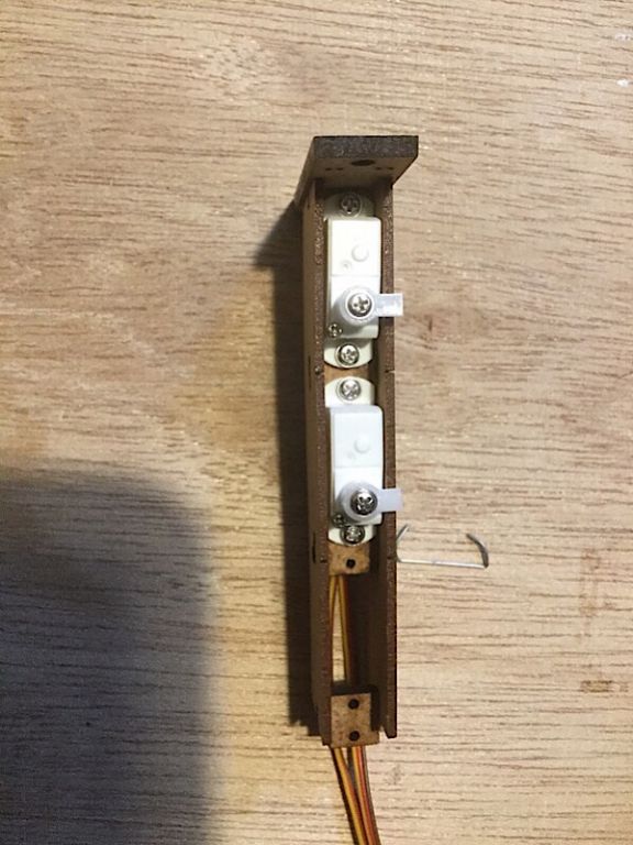 Andrew |
||
|
posted: 24 Dec 2018 19:58 from: Rob Manchester
click the date to link to this post click member name to view archived images |
Andrew Duncan wrote: A happy and peaceful Christmas to you and thank you to all of you who have read about my goings on at the end of the dining room table and to those who have replied with thoughts and ideas over the last year. I find it surprising and really encouraging. Thanks.Hi Andrew, And the same to you too. Thanks for posting your activities on here for us to view. You always make interesting reading. Rob |
||
|
posted: 29 Dec 2018 22:48 from: Andrew Duncan
click the date to link to this post click member name to view archived images |
Thanks very much Rob, kind of you to say so. Kind regards Andrew |
||
|
posted: 29 Dec 2018 23:04 from: Andrew Duncan
click the date to link to this post click member name to view archived images |
Incidentally to pick up on a previous conversation here is a photo of apparent order and calm taken close up of my current progress. .2787_291755_470000000.jpg 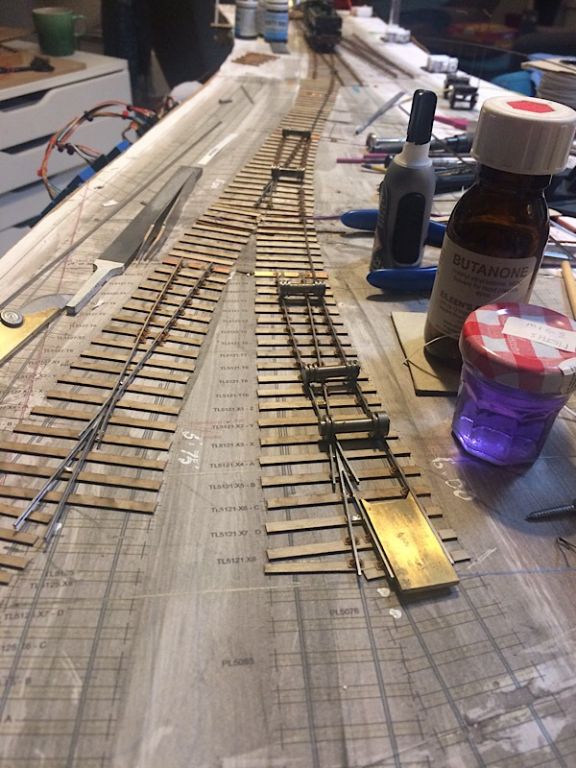 And here’s the same thing taken from the other end, cruelly showing the chaos I really work in. Sadly I’m going to have to give in to Nigel’s theory... 2787_291801_410000000.jpg 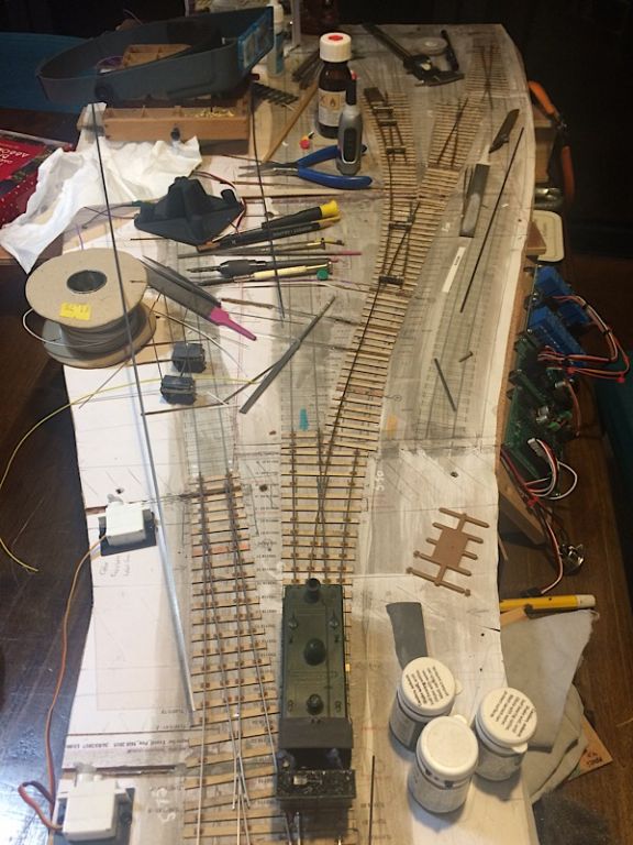 Andrew |
||
|
posted: 30 Dec 2018 08:52 from: Hayfield
click the date to link to this post click member name to view archived images |
Andrew Looks quite normal to me, plus I like to see the order people build their track formations in |
||
|
posted: 31 Dec 2018 01:07 from: Andrew Duncan
click the date to link to this post click member name to view archived images |
Hayfield wrote: Andrew Thanks John Yup there so many different approaches to building track. Indeed this is a different one to my previous efforts as I’m building the crossings separately, directly on a spare Templot plan and then transferring them complete to the waiting sleepers! Not done this before but it does enable me opportunity to give the crossing a good old wash and brush up ( after all the soldering ) that isn’t possible if already stuck in place and, as I mentioned earlier, when using steel rail that’s a real benefit in keeping corrosion at bay. I feel also that it helps me build a more accurate crossing which is so often the part of turnout construction that trips me up! Kind regards Andrew |
||
|
posted: 1 Jan 2019 00:43 from: Andrew Duncan
click the date to link to this post click member name to view archived images |
Cry for help! I’ve just run out of the Exactoscale plastic insulating Fishplates ( the double sided ones with insulating break in the middle) and Exactoscale appear to be out of stock. Does anyone know where I might beg, buy or borrow some? Kind regards Andrew |
||
|
posted: 1 Jan 2019 01:11 from: Rob Manchester
click the date to link to this post click member name to view archived images |
Andrew Duncan wrote: Cry for help!Hi Andrew, Happy New Year to you I just checked my stash and I haven't any Exactoscale one's or anything similar. Sorry. I did have some whiskey earlier.. Best Rob |
||
|
posted: 1 Jan 2019 09:38 from: Andrew Duncan
click the date to link to this post click member name to view archived images |
Rob Manchester wrote: Andrew Duncan wrote:Hello RobCry for help!Hi Andrew, And a happy new year to you as well! No, no whiskey or even whisky, but a good or even average Bordeaux is very much my taste, drunk of course from the correct Riedel glass really brings out that lovely gravelly taste that some have. Incidentally Riedel, if you haven’t come across them do an excellent single malt Whisky glass which if you haven’t tried it you should seriously consider, especially if you’re currently using a traditional whisky tumbler. You might well think you’re drinking a much older more mature spirit. If I’m beginning to sound like a salesman forgive me and ( full disclosure) yes we do sell them! But I’m really just an enthusiast for the product. Thanks for looking in your stash, much appreciated. Here’s hoping that someone either knows a retailer with some stock or has some they’d sell or lend me. I’ll keep my fingers crossed! Kind regards Andrew |
||
|
posted: 1 Jan 2019 12:11 from: Graham Idle
click the date to link to this post click member name to view archived images |
Hi Andrew, I have some frets of 4XX FP01 if thats any use to you. I only live in Salfords so you could pick them up if you are in a hurry for them. Regards, Graham Idle Andrew Duncan wrote: Cry for help! |
||
| Last edited on 1 Jan 2019 12:43 by Graham Idle |
|||
|
posted: 1 Jan 2019 12:44 from: richard_t
click the date to link to this post click member name to view archived images |
I've looked in my stash of 4mm track parts, but no fishplates I'm afraid. Richard |
||
|
posted: 1 Jan 2019 15:00 from: Andrew Duncan
click the date to link to this post click member name to view archived images |
Graham Idle wrote: Hi Andrew,Hello Graham Thank you very much indeed for your offer. May I check that we’re talking about the same thing. I’ve just found a picture of the 7mm version on the web and have added it below. If we talking about the same thing I’d be delighted to take you up on your kind offer. 2787_010958_390000000.jpg  Kind regards Andrew |
||
|
posted: 1 Jan 2019 15:09 from: Graham Idle
click the date to link to this post click member name to view archived images |
Hi Andrew, Yes those are they, I assume the 4XX denotes 4mm. I have 3 full frets and one with 9 fishplates on, if these will help you, please give me a ring on 07732953848 and we can arrange collection. Regards, Graham Andrew Duncan wrote: Graham Idle wrote:Hi Andrew,Hello Graham |
||
|
posted: 1 Jan 2019 19:40 from: Rob Manchester
click the date to link to this post click member name to view archived images |
Hi Andrew, I hope the fishplates for 4mm fit a little better than the version that Exactoscale made for 7mm. I had some of the larger ones and they needed a lot of modification to fit if I remember correctly which is why I went onto using etched ones ( which won't be much use when insulation is required of course ). Thanks for the glasses insight ( drinking not reading ). My whisk(e)y gets drunk from a very old Ravenhead chunky tumbler Rob |
||
|
posted: 1 Jan 2019 21:17 from: Stephen Freeman
click the date to link to this post click member name to view archived images |
I have used both fairly recently without much problem. The only thing I have ever found necesary is to ensure there is no burr on rail web.Easiy sorted. Available from either EMGS or Exactoscale I think. |
||
|
posted: 1 Jan 2019 22:53 from: Andrew Duncan
click the date to link to this post click member name to view archived images |
Thanks very much Graham, I’ll ring you tomorrow Andrew |
||
|
posted: 1 Jan 2019 22:54 from: Andrew Duncan
click the date to link to this post click member name to view archived images |
richard_t wrote: I've looked in my stash of 4mm track parts, but no fishplates I'm afraid.Thanks for looking Richard. Andrew |
||
|
posted: 1 Jan 2019 23:20 from: Andrew Duncan
click the date to link to this post click member name to view archived images |
Rob Manchester wrote: Hi Andrew, Hello Rob Like Stephen I ve not had much problem with them in 4 mm other than the odd one splitting or separating, I should say, so that the two sides were no longer connected. But I discovered that this was due to me not fettling the ends of the rail carefully enough. Once I put a mild chamfer on the web of the rail, all was well! Interesting what you say about the shape not making any difference to the flavour of your whisky. But I think you maybe surprised by how much shape does make a difference. When your thirsty next, humour me, and try it out of some wildly different shapes, a mug a wine glass, tea cup etc and then come back to me and tell me it didn’t make a haporth of difference....you might, but I doubt it! Kind regards Andrew |
||
|
posted: 1 Jan 2019 23:25 from: Andrew Duncan
click the date to link to this post click member name to view archived images |
Stephen Freeman wrote: I have used both fairly recently without much problem. The only thing I have ever found necesary is to ensure there is no burr on rail web.Easiy sorted.Hello Stephen Yup I’ve found a similar problem but eventually found the solution. My problem is that they are out of stock, but Graham has very kindly offered me some which will allow me to finish this baseboard. Kind regards Andrew |
||
|
posted: 3 Jan 2019 10:13 from: Graham Idle
click the date to link to this post click member name to view archived images |
Hi Andrew, I'm around all day today if you want to ring me. Regards, Graham Andrew Duncan wrote: Thanks very much Graham, I’ll ring you tomorrow Andrew |
||
|
posted: 3 Jan 2019 18:33 from: Andrew Duncan
click the date to link to this post click member name to view archived images |
Graham Idle wrote: Hi Andrew,Hello Graham Thanks very much for the fishplates, I’ve already used four pairs this evening when I got in from work. Kind regards Andrew |
||
|
posted: 6 Jan 2019 16:29 from: Andrew Duncan
click the date to link to this post click member name to view archived images |
Hello everyone Another request I’m afraid. I need to dispose of my old 00 layout of Maiden Newton and a very cut down version of Yeovil Pen Mill. Maiden Newton is approx 12’ long and Yeovil approx 10’long. The layout is featured in Iain Rice’s “Railway modelling the Realistic Way” on pages 9, 170, 207, 210, 217, and in his Haynes book “Layout Design” on pages 20, 27, 32. 51, 58/9, 110, 113, 116/7, 129, 138, 156. And both he and I built it over a period of 12 years or so. The track has handbiult turnouts and C&L track. It’s built to finescale standards employing a 14.8mm back to back and 1mm through the flangeways. The buildings are nearly all Rice creations which are I think little works of art. For example he hand painted every flint on the station building and the goods shed and they are all a subtly different colours. The turnout operation is with Tortoises on MN and Seep on YPM. The latter have created problems with the tie bars on YPM and remedial work is needed here. And whilst talking electrics the layout hasn’t run in about 4years so will need work to get it operational again, anything from just cleaning the track to resoldering broken connections is my best guess. It doesn’t include any rolling stock. I may include the Scalefour Society lever frame at Maiden Newton. On YPM I’m NOT intending to include the station building or overall roof as I can reuse them on the new YPM. This is an urgent disposal as we need the space for the business as we’re having to move out of our warehouse at the end of the month and use our home to store some of stock for the business until I can find an affordable storage solution. So my reality is that if I can’t get rid of the two stations I will have to break them up and take them to the dump, which I’d find difficult! So any offers would be welcome, but at the end of the day what I really want is for it go to a good home. Kind regards Andrew |
||
|
posted: 6 Jan 2019 18:43 from: Andrew Duncan
click the date to link to this post click member name to view archived images |
Here are a few photos that show firstly Maiden Newton looking south down the line towards Weymouth. 2787_061333_040000000.jpg 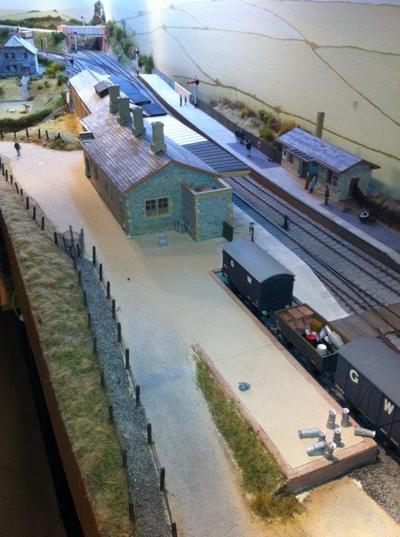 And here’s the goods shed 2787_061336_180000000.jpg 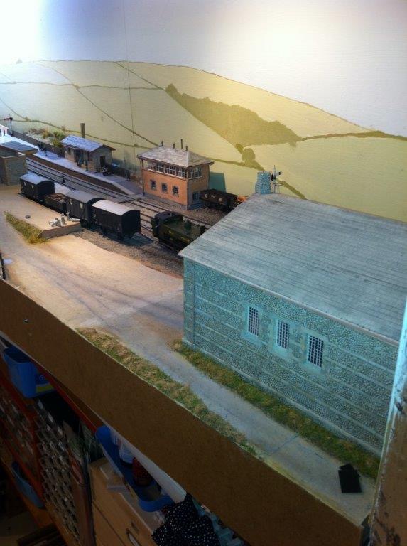 Hers an overall view of Yeovil Pen Mill 2787_061337_450000000.jpg 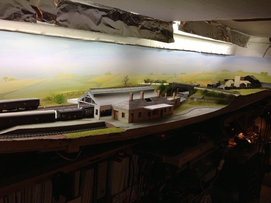 And lastly a view over the roof of the Brunel train shed towards the MPD and south towards Maiden Newton and Weymouth 2787_061339_210000000.jpg 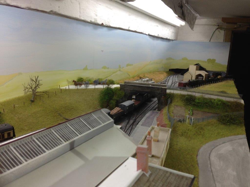 Andrew |
||
|
posted: 8 Jan 2019 01:34 from: Andrew Duncan
click the date to link to this post click member name to view archived images |
Ok onward and upward. A photo or two of turnout building progress and in particular this new tiebar arrangement copied from Mike Norris with amendments from Howard Bolton. Seven out of the eight turnouts now have switches fitted and new unobtrusive tiebar installed as well and, because it’s easy to do with servos topside, I’ve also connected them up to their switches and so far it’s all looking good. 2_072054_010000000.jpg 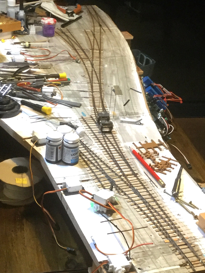 Below are few photos of the new tiebar during construction. I must say that I’m very enamoured with them so far: so much less obtrusive than the moving sleeper that I was using and not difficult to build. So firstly there is the copper fibreglass strip suitably gapped once in the mid point on one side an naturally twice on the other to not introduce a thin weak point ( thanks to Howard for this subtly that had passed me by). A couple of holes drilled through for the operating wire tother end of which one solders the switches to. 2_072058_400000000.jpg 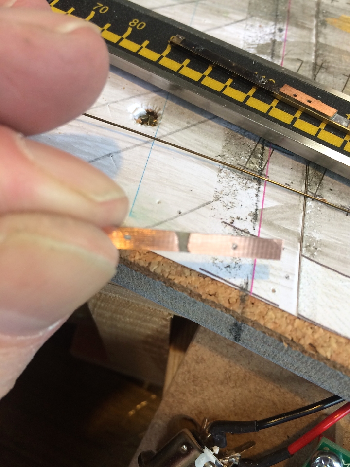 And here’s the completed tiebar ready to be installed. I tried to make gentle bends on the .45mm wire using pliers with round jaws to reduce the chance the metal snapping with metal fatigue. 2787_072010_340000000.jpg 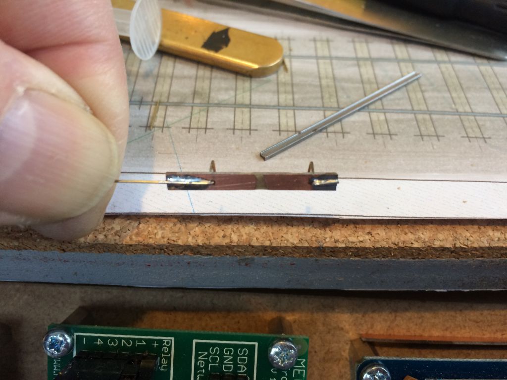 And here’s a side view of how the wire sits in the web of the rail. Very neat! 2787_072013_220000000.jpg 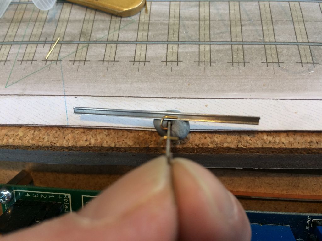 Andrew |
||
|
posted: 14 Jan 2019 00:25 from: Andrew Duncan
click the date to link to this post click member name to view archived images |
Hello everyone Progress in the last week has been steady rather than startling. The basic turnouts have been completed less their check rails and as you can see from the photo I’ve now made a start on them( check rails). What I’m finding though is that they are all under gauge at the crossing by a smidgen, but it’s enough to stop the check rail gauge sliding nicely into place when setting out the checkrail, so I’m finding myself sliding a sharp knife under a number of chairs (either side of the check rail area ) that are holding the stock rails, to ease them out a tad. There’s lots been written about this and I’m pretty certain it’s inclination of the rail in the chairs that’s being held upright by the roller gauges, whilst the glue sets, that is causing it. Perhaps I should make a couple more of the simple brass block gauge that I also use which has no clamping action, to allow the rail to sit naturally in the chair at 20 degrees(?) whilst the glue sets. Has anybody got a favourite method of avoiding this problem? 2787_131918_550000000.jpg 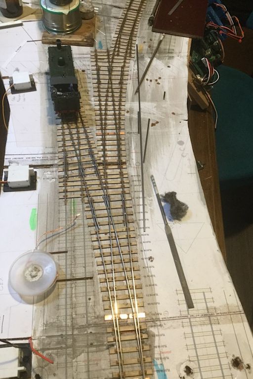 That’s it for tonight I think. Kind regards Andrew |
||
| Last edited on 14 Jan 2019 00:26 by Andrew Duncan |
|||
|
posted: 14 Jan 2019 00:48 from: Rob Manchester
click the date to link to this post click member name to view archived images |
Hi Andrew, I don't think it will work very well with the rails inclined by 20 degrees As to the rail being held by the gauges and then easing itself back when the gauges are removed it depend on what depth of the rail is held in the gauge slots and how tight the gauges are on the width of the rail head. Remind me what size turnouts these are ? Time for a dram of Aldi malt in my chunky Ravenhead glass - some people never learn Rob |
||
|
posted: 14 Jan 2019 01:09 from: Martin Wynne
click the date to link to this post click member name to view archived images |
Andrew Duncan wrote: What I’m finding though is that they are all under gauge at the crossing by a smidgen, but it’s enough to stop the check rail gauge sliding nicely into place when setting out the checkrail, so I’m finding myself sliding a sharp knife under a number of chairs (either side of the check rail area ) that are holding the stock rails, to ease them out a tad.Hi Andrew, If you are using inclined rails, it is important that the gauge slots are deep enough only to engage the rail head. Because of the corner radius on the head, the rail can then easily rotate to 1:20 inclination in the slot: 2_291255_350000000.png  If the slots are too deep, the easiest solution is to wind some fuse wire into them until they are not. A tiny smear of paint will seal the loose end of the wire. The gauge of the track should have no effect on the positioning of check rails. If you are using multi-slot gauges having more than 2 slots, please don't. Please? This is how the gauging of check rails should work: 2_102021_190000000.png 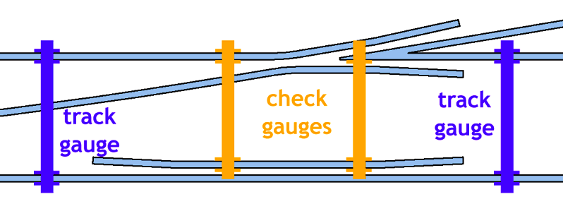 More information about gauging is here, just add 2mm to everything there for EM: http://00-sf.org.uk If using combined check rail/stock rail chairs (as far as I know there are none such available for EM, despite the Exactoscale web site describing 0.8mm check chairs as "EM" -- they should be 1.0mm for EM), it is important to set them using the check rail gauges and check rails. The stock rail can then be left to its own devices through them, regardless of its gauge. cheers, Martin. |
||
|
posted: 14 Jan 2019 14:18 from: Andrew Duncan
click the date to link to this post click member name to view archived images |
Rob Manchester wrote: Hi Andrew,Hello Rob, 20 degrees? Well perhaps not ! I could tell you it was late in the day, but you might think that an excuse? I could tell you that I had just a senior moment...but surely I'm too young for that! I could tell you amongst all the O levels I failed, that I failed maths miserably and completely ( and my failures in education were quite impressive), and that might sound a tad more likely. Or maybe I just didn't stop to think. what everthe truth of the matter thank you for the correction. As to size of turnout they are quite sharp being between 5.5. to 6.00. Why do you ask? Now as to your drinking habits, I see it as my task to shed a little light! Whilst you, in your youth were evidently studying complicated long division sums and geometry, obviously, I was sampling the delights of various forms of fermented fruit which seemed to have a greater appeal and relevance to my life at the time. Long story short this leads me to conclude that drinking whisky out of a Ravenhead tumbler is not quite where "it" is. If I promise to never lay my rails at 20 degrees again, I challenge you to do the same with your tipple! Odd where conversations about model railways end up really. Kind regards Andrew |
||
|
posted: 14 Jan 2019 17:06 from: Rob Manchester
click the date to link to this post click member name to view archived images |
Hi Andrew, Just curious about the turnout sizes, that is all. Do you use 3-point gauges at all or just roller types ? Martin's comments re filling the slots in roller gauges apply also to the 3 point types. As for my boozing habits in earlier years - we used to frequent the pubs and knock back the ale before turning to the beauty of the grape at a later hour. Reason ? Simple, the pubs called last orders at 10:20 but the wine bars ( serving food If you don't stop laying your rails at 20 degrees I will send Network Rail's grinder along to level the tops for you. In return you may throw charity shop Ravenhead tumblers at your garden wall in the hope that voodoo makes mine turn into a fine glassware item. Bottoms up. Rob |
||
|
posted: 14 Jan 2019 23:46 from: Andrew Duncan
click the date to link to this post click member name to view archived images |
Martin Wynne wrote: Andrew Duncan wrote:Hello MartinWhat I’m finding though is that they are all under gauge at the crossing by a smidgen, but it’s enough to stop the check rail gauge sliding nicely into place when setting out the checkrail, so I’m finding myself sliding a sharp knife under a number of chairs (either side of the check rail area ) that are holding the stock rails, to ease them out a tad.Hi Andrew, Thank you for your very clear reply. And in particular thanks for the tip of reducing the depth of the gauge slot with wire, simple and I hope straightforward to do. I am using multi slot roller gauges but only use the outer slot for holding the rails to gauge. And I’ve filled away the inner slot completely on two of them so that I can still use them in the crossing area. They’re from C&L I think or it may have been the EM society? See photo below. I’m not using the check rail chairs either as they’re not available as you say. I am using the checkrail gauge for setting the checkrails off from the crossing and the one I use is also in the photo. Thanks again for your help and advice Kind regards Andrew 2787_141845_360000000.jpg 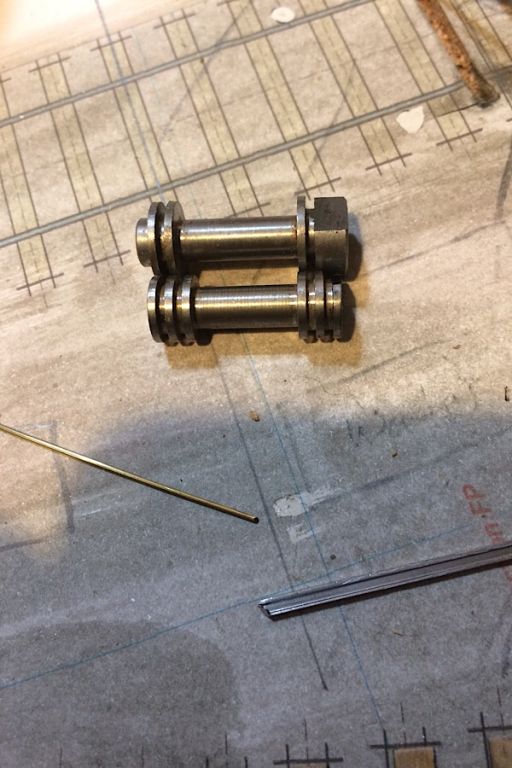 |
||
|
posted: 15 Jan 2019 00:25 from: Andrew Duncan
click the date to link to this post click member name to view archived images |
Rob Manchester wrote: Hi Andrew,Hello Rob There are some evocative memories in that picture you paint. I certainly remember the extortionate interest rates which I seem to remember taking taking rather for granted at the time and making 5 gallons of wine at a time and never getting round to bottling it. Just siphoned it out into a jug and that was as good as it got! Well, back to track building and no I don’t seem to get on with three point gauges. I use the roller gauges i referred to in my reply to Martin and a home made flat brass plate about 40mm long that just sits between the rails. Those plus the little strips of nickel silver 1mm thick gauging the flangeway in the crossing about sums up my armoury. Just finished the remaining checkrails tonight and my track testing wagon thing with the long brass arms went through all of them with barely a murmur. Impressive or what!! I can see I’ve a way to go on the booze receptical front, but in a gesture of goodwill I’ll undertake to never lay anymore rail at 20 degrees. Kind regards Andrew |
||
|
posted: 15 Jan 2019 07:42 from: Stephen Freeman
click the date to link to this post click member name to view archived images |
Hi, The grooves do look deeper than those on the gauges I have. They came from C&L some years ago and only just hold the rail head, though as far as I know they never made a separate checkrail setting gauge. Andrew Duncan wrote: Martin Wynne wrote:Andrew Duncan wrote:Hello MartinWhat I’m finding though is that they are all under gauge at the crossing by a smidgen, but it’s enough to stop the check rail gauge sliding nicely into place when setting out the checkrail, so I’m finding myself sliding a sharp knife under a number of chairs (either side of the check rail area ) that are holding the stock rails, to ease them out a tad.Hi Andrew, |
||
|
posted: 15 Jan 2019 09:07 from: Hayfield
click the date to link to this post click member name to view archived images |
Over the weekend I was party to a discussion between C&L and their roller gauge supplier/manufacturer and to some extent the penny is starting to drop. New gauges are being ordered and will as you expect will be plastic chair compliant There is some hesitation removing the inner slots on roller gauges, they can however see that as they stand without flats being made at one end on the outer rim and at the other on an inner rim, the former to allow gauging over the common crossing, the latter over the switch end. They are now exploring the supply of wing rail gauges As for 3 point gauges, I have successfully adapted an older EM gauge (large round pin version)by removing the rear part of the pin. For some time I have used my newer style of Exactoscale P4 gauges which only have inner flanges, gauge widening is done manually and no instructions were available as to the radii and amount of widening to use. In the past I have erred on the cautious side by mainly using the smallest one except on the smallest of radii where I use the smallest two sizes A quick heads up with C&L, a new website is expected to be live within a week or so, until the website changes visibly always phone as the existing website has a known glitch. Phone after making an order, and if waiting for an order phone them, this is on their home page Due to technical difficulties I am unable to do any administration work within the website this includes stock numbers, pricing and the printing of orders from 19739 dated 21-09-2018. I do have a work round on these orders which can be placed as usual and follow the same payment process, but it is essential that you call me during my normal office hours with your order number. If you come across stock item reading zero please call me. Apologies for the inconvenience caused, a new website is being worked on but currently do not have an implementation date. Update last weekend hope to go live in a week or so |
||
| Last edited on 15 Jan 2019 09:10 by Hayfield |
|||
|
posted: 15 Jan 2019 23:47 from: Andrew Duncan
click the date to link to this post click member name to view archived images |
Hello John It’s good to hear that C&L are going to be supplying gauges that won’t force the rail to the vertical and that they’ve a new website in the offing as ordering from the current site is quite a challenge and long winded. Kind regards Andrew |
||
|
posted: 16 Jan 2019 00:04 from: Andrew Duncan
click the date to link to this post click member name to view archived images |
Hello Stephen If yours with shallow slots are C&L then I think mine must be from the EM gauge society ...probably ? Kind regards Andrew |
||
|
posted: 16 Jan 2019 10:48 from: Stephen Freeman
click the date to link to this post click member name to view archived images |
I bought mine some time ago, when it was run by Brian Lewis, early 2000s so could have changed since then. Just checked, EMGS sell a whole gamut of gauges so most probably theirs. They do appear to be out of stock of 3 point gauges. Andrew Duncan wrote: Hello Stephen |
||
| Last edited on 16 Jan 2019 10:51 by Stephen Freeman |
|||
|
posted: 20 Jan 2019 01:45 from: Andrew Duncan
click the date to link to this post click member name to view archived images |
Stephen Freeman wrote: I bought mine some time ago, when it was run by Brian Lewis, early 2000s so could have changed since then. Just checked, EMGS sell a whole gamut of gauges so most probably theirs.Hello Stephen Yes I think you right about the provenance Andrew |
||
|
posted: 28 Jan 2019 23:02 from: Andrew Duncan
click the date to link to this post click member name to view archived images |
Hello everyone So the baseboard that was not meant to have anything underneath ....well it didn’t quite work out that way, but it’s far less then on previous boards and there is little or nothing that needs adjustment underneath and that is a real plus! Here’s a photo of the underside with “only” servo power leads and crossing polarity leads evident. I also tried to keep the two apart and to not have them running parallel when they’re close to each other. Instead I’ve crossed them at right angles ish where it’s necessary. 2787_281713_560000000.jpg 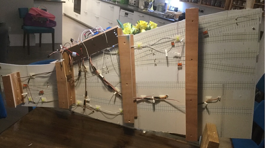 And the little white tags you can see are the cable numbering labels with each wire identified at each end using a Brother Ptouch labeller that I think Andy recommended? Nice bit of kit if you can understand the instructions, which generally I can’t and this time completely defeated my poor brain. However I have a very cooperative wife who usually can fathom these things out but in this case it even got the better of her. So child number one had to come to our rescue. Hes a computer programmer and he struggled a bit. However in the end the fiendish brain of whoever wrote the instructions was no match for the combined might of the Bluett- Duncan family who eventually triumphed! And, I discovered it could do sequential labelling as well. Fanatastic! Here are a couple more photos of progress to date. Having wired up the stockrails to the to the relevant switch blades, the crossing feeds through to the blue relays controlled by the Megapoints boards and the servos also wired up to the Megapoints boards, I’m getting close to testing the track under power. Very exciting! And yes I know it looks like nothing on earth at the moment, but with a can of Halfords grey primer wafted over it in a week or twos time, it’ll take on a more homogeneous feel I think?🤪 less Battle of the Somme more Seurat or Manet. 2787_281735_190000000.jpg 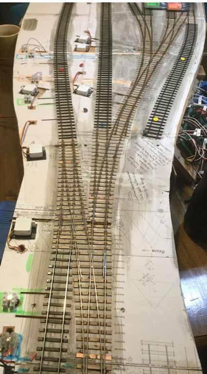 And here a last picture of a close up of my crude colour coding for the three different “ Districts “ that split the board into Up Line, Down Line and GoodsYard. So the wires are buried in trenches in the cork and the colour coding hopefully means I’ll connect the correct wires to the right switches. Ive just realised that I actually need to build that switch assembly before I can fire the thing up and see something moving. 2787_281740_330000000.jpg 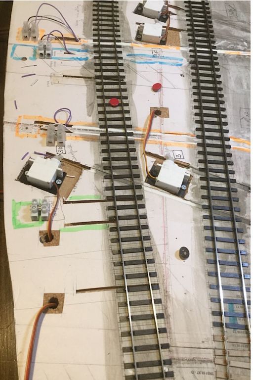 Kind regards Andrew |
||
|
posted: 21 Feb 2019 21:16 from: Andrew Duncan
click the date to link to this post click member name to view archived images |
Hello everyone A brief update. In two words “it works”. And no one is more surprised than me! But yes it’s working ok and I think that it’s my best yet in terms of smoothness of running through the crossings in particular, which is very pleasing! I’ve just today given the trackwork a waft over of Halfords grey primer which has improved the look a little and now I need some fine weather to take it outside to spray the sleepers a light / medium brown grey and the sides of the rail a more rusty colour. Here a picture of it’s current state 2787_211559_070000000.jpg 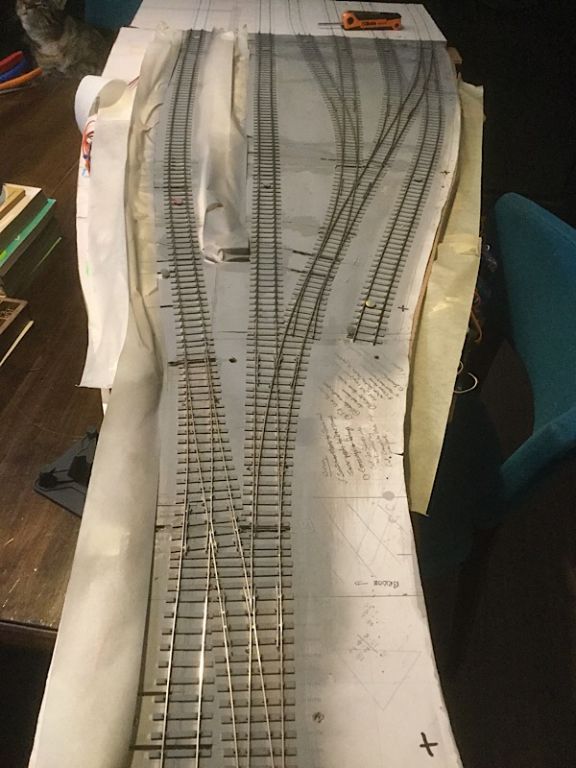 And here’s one of the baseboard temporarily in position on the layout. Only one more baseboard to go and that’s the station almost complete trackwise. 2787_211609_210000000.jpg 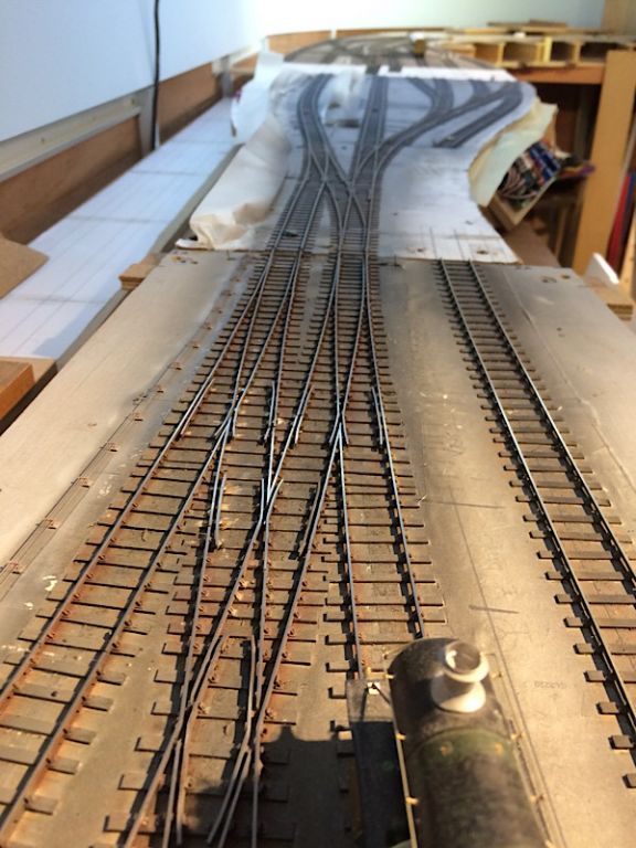 Kind regards Andrew |
||
|
posted: 21 Feb 2019 23:52 from: Nigel Brown click the date to link to this post click member name to view archived images |
Always think track looks best when it's in that state. Mucking it up with ballast, paint and other scenic stuff ruins it! | ||
|
posted: 22 Feb 2019 18:21 from: Andrew Duncan
click the date to link to this post click member name to view archived images |
Nigel Brown wrote: Always think track looks best when it's in that state. Mucking it up with ballast, paint and other scenic stuff ruins it!Hi Nigel Yup I agree it’s really tricky getting the ballast looking good/ lifelike. Haven’t achieved it to my satisfaction so far. Andrew |
||
|
posted: 24 Feb 2019 15:47 from: Andrew Duncan
click the date to link to this post click member name to view archived images |
I got out my Iwata Neo trigger operated airbrush first thing this morning and had two goes at spraying the sleepers firstly , as it turned out a slightly browner grey than Halfords grey primer and actually maybe I should have left it at that. At the time I didn’t think it looked very different to the primer so I then experimented with more brown and a shade or three darker. In strong sunlight it look pretty good. So then I tried ever so gently and sparingly sparying the side of the rail a sort of rust colour. I then put it in place on the layout to photograph and suddenly it became ever so dark. Quite extraordinary the difference and I think far too dark probably. Below you can see my problem. 2787_241040_020000000.jpg 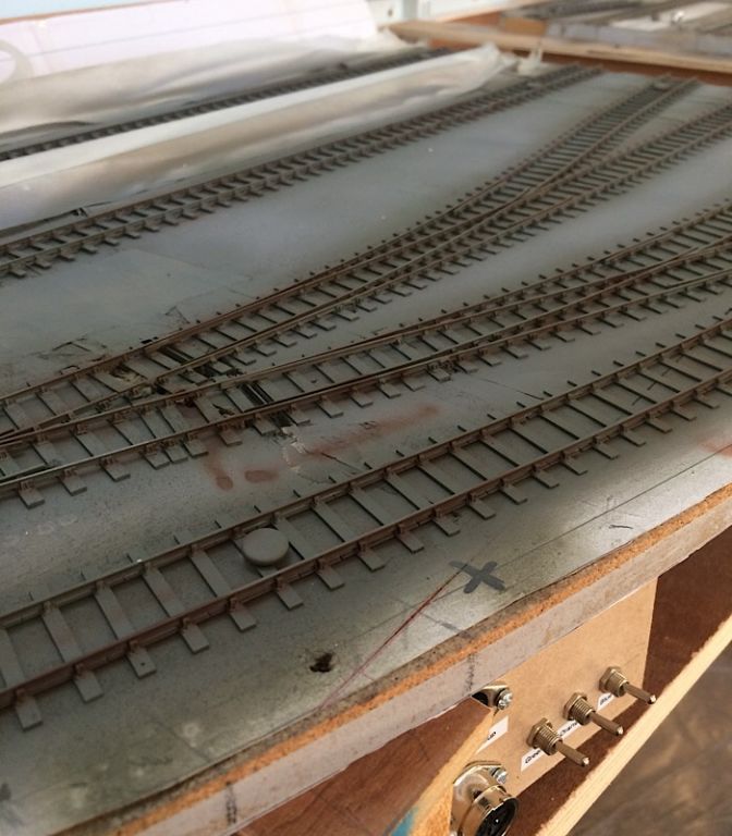 Once ballasted of course that will lighten it. Time to let it “sink”and see how it looks in a bit. Andrew |
||
|
posted: 24 Feb 2019 17:31 from: Nigel Brown click the date to link to this post click member name to view archived images |
For sleeper colour it may be about right; I use a sort of graphite on mine. When ballasted you'll only see the sleeper tops. It also depends on what sort of lighting you intend to use, if any. For rail I tend to use something distinctly lighter, a lightish greyish brown. A lot of layouts these days seem to use a sort of pink, which looks horrible. Rail sides and chairs quickly weather to a greyish hue, rather than bright rust. Nigel |
||
|
posted: 28 Feb 2019 00:16 from: Andrew Duncan
click the date to link to this post click member name to view archived images |
Nigel Brown wrote: For sleeper colour it may be about right; I use a sort of graphite on mine. When ballasted you'll only see the sleeper tops. It also depends on what sort of lighting you intend to use, if any.Hello Nigel I’ve been thinking more about your opinion on track colours and wondering if in fact grey might not be that far off for sleeper colour. I’ve always tried for some sort medium light grey brown colour in an attempt not to copy the real thing up close, but to give an impression as viewed from 50 odd scale yards (so about two feet) away. Like you, I don’t think bright orange or pink convinces as rust on rail unless you’re right up close and even then it has to be oh so subtle. More thought and experiment are needed me thinks. Andrew |
||
|
posted: 7 Mar 2019 14:57 from: Stephen Freeman
click the date to link to this post click member name to view archived images |
Sleeper colour is one of life's variables. The wooden timbers started out life freshly cresoted, so would be black. Weathering would turn them lighter, add to that the effect of rust coming from the chairs. At places with standing locos, the track as a whole would probably be darker due to leakage of water/oil/grease. Braking locos etc would also have an impact (probably not too heathily either). Fishplates should normally be black as long as the PW staff remembered to oil them! Track would also be subject to various "deposits" both randomly and in specfic areas. Whatever you choose an all over colour is probably not going to be realistic. |
||
|
posted: 10 May 2019 22:52 from: Andrew Duncan
click the date to link to this post click member name to view archived images |
Hello everyone It’s been a while and indeed I’ve not been idle, but a lot of it’s been rewiring the junction baseboard and building my first Merg DCO (district cutout) which I fearbI’ll never get to work. But that’s probably just me and my complete lack of knowledge of such things. It certainly won’t be because of the lack of really practical advice. Merge have a forum very much like this one, where a complete starter can ask the simplest most basic of questions and get very practical help. So far so good. Tomorrow I’m intending to do the final testing to see if it works with the ICs in place. I’m not sure what an IC is but there are dire warnings about the consequences of installing them the wrong way round! Wish me luck Andrew |
||
|
posted: 11 May 2019 10:16 from: Judi R
click the date to link to this post click member name to view archived images |
Don't forget that MERG do offer a "get you going" service which is mentioned on our forum. If all else fails, then our Technical Support Manager will look at it and get it going for you if you post it to him. Judi Rastall |
||
|
posted: 11 May 2019 11:40 from: Andrew Duncan
click the date to link to this post click member name to view archived images |
Judi R wrote: Don't forget that MERG do offer a "get you going" service which is mentioned on our forum. If all else fails, then our Technical Support Manager will look at it and get it going for you if you post it to him.Hello Judi Thanks for your message, I'm hoping that my pessimism is misplaced and that everything will go swimmingly. I suppose I said that I feared it wouldn't work because in electronics I have no experience of fault finding. Indeed I find tracing a short circuit on one of my baseboards, a long drawn out process that sometimes can takes me days to track down and that's with something that is a simple + or - that I've designed and built myself. You can probably imagine therefore that the thought of tracing a problem on a tiny circuit board that seems to talk a different language and has things on it that have more in common with magic than any reality I understand, is a big leap. Having said that I've been very impressed by both your (Merg) support and, that I've got through the first stage of testing successfully! So keep your fingers crossed that I make it through the last stage without blowing the thing to kingdom come! Thanks again for you help on the Merg forum Kind regards Andrew PS I wasn't aware of the get you going service. Excellent service to offer. |
||
|
posted: 11 May 2019 23:09 from: Andrew Duncan
click the date to link to this post click member name to view archived images |
Hooray it worked! It’s a bit of a long story but in the end I got the DCO working ok (with a,little more help from Geoff on the Merg forum)I think. I say I think because it’s not yet been tested out in anger, but all the signs suggest it’ll be fine in use. Andrew |
||
|
posted: 11 May 2019 23:49 from: Andrew Duncan
click the date to link to this post click member name to view archived images |
Ok so here are few pictures of stuff that I’ve been up to in the last couple of months. Below is a picture of the control panel I’ve just made that holds the ZTC 511 controller and all the power supplies needed for it and the servos. The switches you can see ( two missing at present) are the district switches, UP MAIN, DOWN MAIN, MARSHALLING YARD, BRANCH LINE which as the title suggests cut out any one of these power districts. And on each board each district can be switched out locally for that board which makes trouble shooting easier. There’s a LED below each switch to show its live. 2787_111813_160000000.jpg 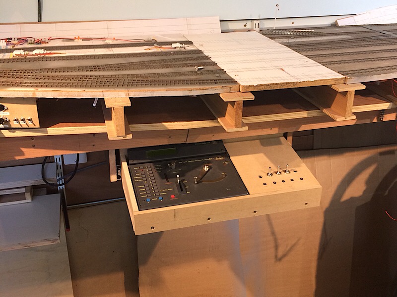 The control panel is mounted on a pair of drawer runners and behind it (you can see in the picture below,) it pulled out showing where the power supplies live. 2787_111825_390000000.jpg 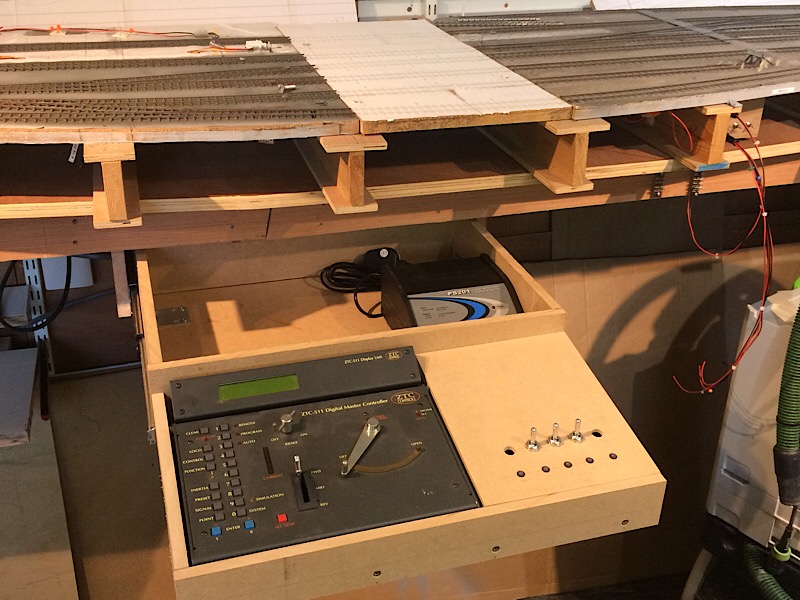 And here,s a picture of my collection of azaleas which are about to burst into bloom ...sorry just couldn’t resist 2787_111831_250000000.jpg  And here is one of our cats trying to help me understand complicated long division sums that the Merg site refer to as basic electronics!!! Truffle, the cat, (all our cats are named after food, I should say that I run a company selling cookware and my wife's French and loves cooking, my middle daughter’s a pastry chef so I mention this so you don’t think my life’s all beer and peanuts.) couldn’t make head or tail of it either and eventually left in search of more interesting tit bits. In fact I think in this photo he was already getting distracted, probably by the catnip which he’s very partial to. 2787_111846_420000000.jpg  And here is the junction baseboard still with its relay electrics in tact....but not for long. The relays that control the crossing polarity have been very iffy for some reason and in the end back at the end of March I finally got fed up with them and replaced them all with Gaugemaster Autofrogs ( frog juicers). Huge reduction in wiring! I’ve still got an intermittent short circuit on the branch line on that board but the change has made most of the board pretty reliable...just a little way to go. 2787_111854_230000000.jpg 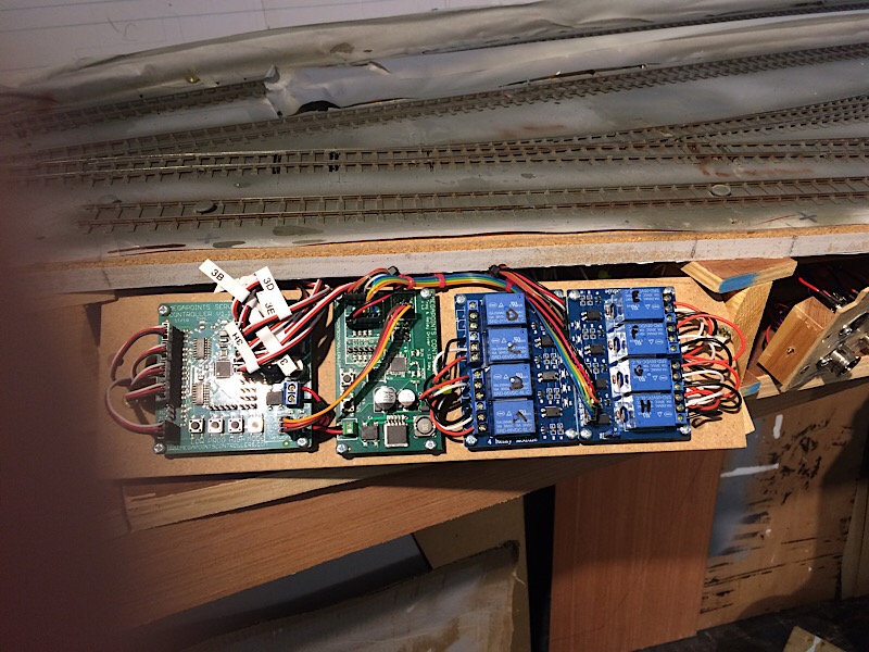 I think that’s about it for tonight. Time for a wee dram before bed perhaps? Kind regards Andrew PS in the end it turned into a couple of madeleines dipped in the apricot jam, washed down with some cooking brandy and a mug of tea. Heady stuff. |
||
| Last edited on 12 May 2019 00:37 by Andrew Duncan |
|||
|
posted: 28 May 2019 03:12 from: Andrew Duncan
click the date to link to this post click member name to view archived images |
Hello everyone I’ve been concentrating on electrics of late which, as it’s hidden, can easily get overlooked and, in my case perhaps, not well enough planned. For instance I wish now that I had surface mounted all the servos “topside” as I did with board no3 and put the track power topside as well again as I did with that board. There’s no point in crying over spilt milk but more thought at the planning stage may well have lead me to that conclusion especially as that was how I wired my mark1 version of Yeovil Pen Mill in 00 years ago. So to continue the story of the MERG district cut outs I’ve now successfully built a second one that seems to work ok in basic testing I’ve done so far. When talking to John Gower at Railex last Saturday he thought that I may have to adjust them to be a little less sensitive to cope with the “Autofrog” frog juicers I’m using from Gaugemaster for switching the polarity of the crossings. But, if I’ve read the instructions correctly, that is an easy matter to address with jumpers provided. So not a lot to see but progress is being made and soon I need to start thinking about the final station board, board no6, as I’m intending to take that to the Missenden summer school this July. That’s it for the moment I think. Kind regards Andrew |
||
|
posted: 2 Jun 2019 23:12 from: Andrew Duncan
click the date to link to this post click member name to view archived images |
Hello everyone A little more progress with the electronics. I’ve now built and installed three out of the four “DCO’s” from MERG and tonight made a start on my fourth one. Earlier I wired up the three in the picture below to the ZTC 511 and all seems to be ok albeit I’ve not yet run a loco with them in circuit. The second picture shows all the green LEDs alight on the DCOs, just to prove that even I can build not just one, but three electronics boards that work! 2787_021750_140000000.jpg 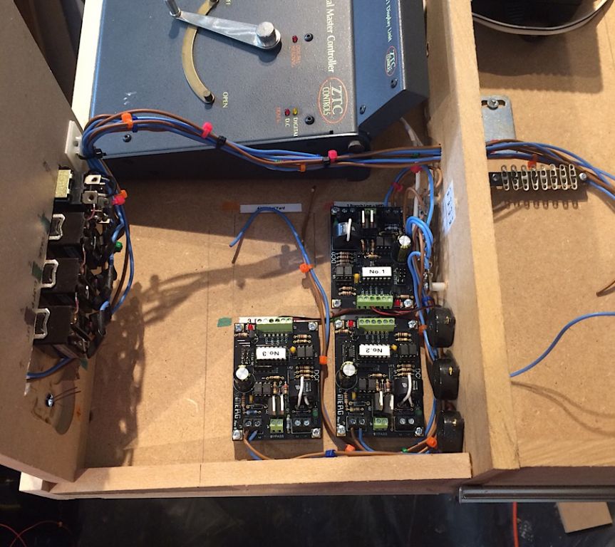 2787_021749_200000000.jpg 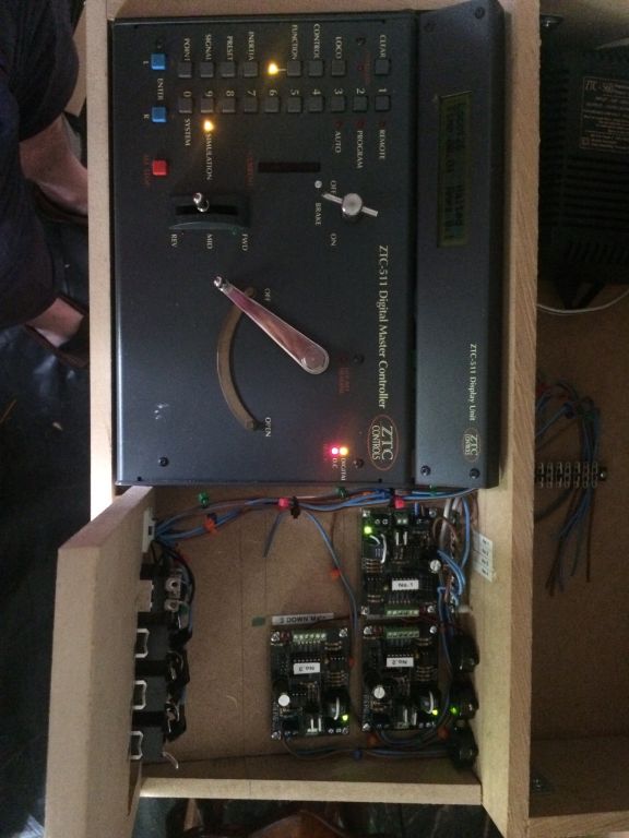 That’s it for now. Kind regards Andrew |
||
|
posted: 24 Jul 2019 21:44 from: Andrew Duncan
click the date to link to this post click member name to view archived images |
Hello everyone I’m off to Missenden this weekend and am hoping to make a good start on the last station baseboard number 6. But just to keep you up to date here’s a few photos of some progress on the electrics. Below is the 4th DCO nearing completion and yes it did work just like the previous three have. I’m really glad I came across the clamp that’s holding the board in the picture. It made installing all the components a lot easier than had I been without it. I bought mine on CPC website. 2787_241556_050000000.jpg 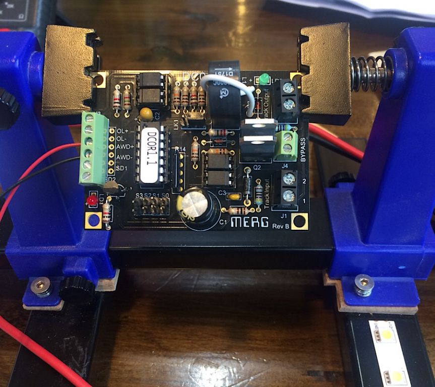 The next picture shows the main traction wiring (split into four districts) gradually making progress along the length of the layout which, after reading much of Davey Dicks ebook on the Merg website, I took his advice and have twisted each pair( positive and negative) to reduce the chances of radio interference. I’ve done the same with the Servo power bus as well to reduce the likelihood of unpleasant surprises! 2787_241604_240000000.jpg 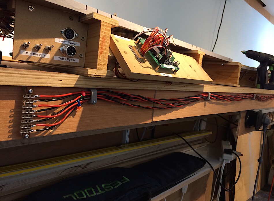 Next is a picture of the latest state of the control panel. As you can it’s beginning to look a little crowded in there and with hindsight I should have made it much deeper. It’ll do for the moment and I’ll have to see if I ultimately feel I need to replace it with something better?2787_241623_150000000.jpg 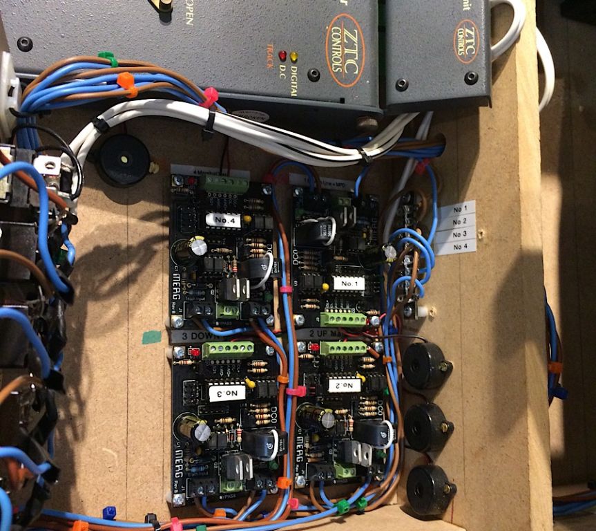 And lastly here is board number 6 in preparation to take with me on Sunday. The plan is stuck down after a few false starts and the black lines going across the board at various points are the channels I’ve cut for the metal tubing for point control. I’ll also need to cut similar channels for the surface run wiring that I started to adopt when doing board 3. I still took the trouble to stick a mirror image of the plan to the underside of the board as I have the unhappy knack of completing forgetting what I’ve just seen on the top when I turn it over to do something underneath! Sad but true!! 2787_241628_500000000.jpg 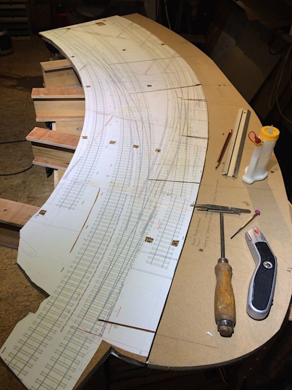 Ok I think that’s it for tonight. Bracing myself for tomorrow’s heat wave! Kind regards Andrew |
||
| Last edited on 24 Jul 2019 23:39 by Andrew Duncan |
|||
|
posted: 3 Aug 2019 18:15 from: Andrew Duncan
click the date to link to this post click member name to view archived images |
Hello everyone Well I’m back from Missenden and despite my apparent progress I have had a really good, if at times, challenging time! As you can see below I managed to stick down some sleepers, install some surface wiring in tubes and complete a double slip. Not exactly what I had in mind as I foolishly thought I’d get at least both slips done and possibly a turnout or two. Well let me tell you there was a time at close of play on Thursday night that I bitterly regretted having chosen to put a double slip in the goods yard to save space and decrease the sharp radius going into the goods shed. Double slips on a curve I discovered are for the experienced or foolhardy. As I’d not built one before you can see which category I came into. However one of the great things about Missenden is the plentiful supply of expertise on which to call. So my thanks go to Tim Peacock and Tony Gee without whose collective advice I’d still be there wondering why everything fell off and to my other chums in Studio 1, John G, Charley, Nigel, Chris, Andy and last but least John W who donated his biscuit ration to me....kept me going. And whilst I’m listing the great and good I’ll indulge in a spot of name dropping in the person of Barry Norman who thought baseboard no 5 ( that I also took with me) looked pretty good. If it’s good enough for Barry, it’s good enough for me! (Edit) In short the collective power of being in the presence of all this knowledge and encouragement, both practically and psychologically, got me through. I dont know about you, but I need both these qualities around me when the going gets really tough and I find my own resources and determination are just not up to the job! I suppose what I’m talking about here is team work. Something I may take for granted at work but don’t usually experience in my hobby other than on forums like this one. Missenden is a really inspirational place to go for any modeller( experienced or inexperienced), I doubt that there was a person there who didn’t take something of real value away with him at the end of the week. So my thanks to the organisers Mick, David and Simon for arranging everything so well and the Abbey people who made us so welcome. Anyway here’s the photo of my work and yes it does work if a little lumpy on some roads...some more fettling should sort this out. In the second picture incidentally I’ve got two pairs of the blades hooked up to a couple of servos as well. Kind regards Andrew 2787_031313_080000000.jpg 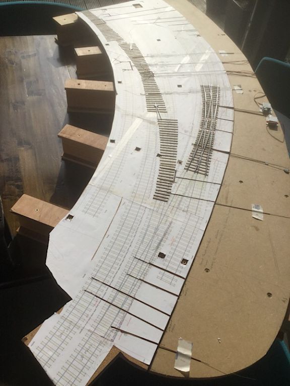 And here’s a bit more detail .... 2787_031314_180000000.jpg 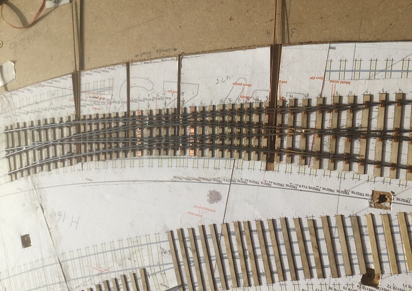 |
||
| Last edited on 4 Aug 2019 03:42 by Andrew Duncan |
|||
|
posted: 6 Aug 2019 15:14 from: Andrew Duncan
click the date to link to this post click member name to view archived images |
Hello everyone Here’s a little more detail on what tripped me up that I thought you might be interested in especially if you’re considering doing something similar and haven’t done it before. The biggest problem that I encountered and hadn’t come across before (because even the three diamonds I’ve built have all been on the straight) was the wheel hitting the end of the internal stockrail / closure rail where it is chamfered off, in this case 1:7.5 which is the same ratio as Ve, Despite what I fondly imagined was painstaking trouble over alignment I still managed to make them too long. And as a result spent a happy hour or so filing them back. But If you go too far with this filing you may end up with the wheels dropping into the Ve. If his happens, and luckily for this didn’t, then I’m told you can put a strip of Evergreen or Slaters into the gap to support the wheel flange as it crosses. I believe they’ve done this at Pendon to good effect. You do need to have all wheels with a standard flange depth to get awards with this dodge. I’m not sure I’d get away with it completely as I use mainly Gibson wheels but do have the odd loco or two with Ultrascale and I’ve never measured them to see how they compare? Alternatively I could have taken Martin’s advice and gone for moving K crossings. Anyway I hope that you can see where I’ve had to shorten the chamfered rail ends, none too neatly I’m afraid but it works. 2787_061006_050000000.jpg 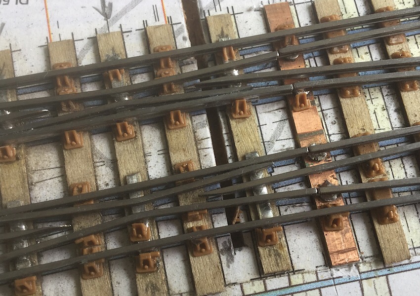 The trench you can see in the middle of the photo is for wiring and just to the left of it is one the offending chamfered rail ends that gave me so much grief! That’s it for now Kind regards Andrew |
||
| Last edited on 7 Aug 2019 07:15 by Andrew Duncan |
|||
|
posted: 6 Aug 2019 18:18 from: Tony W
click the date to link to this post click member name to view archived images |
Hi Andrew. I think you are either very brave or very foolish attempting such a combination. My personal limit for the angle of a fixed diamond crossing in EM is 1 in 7 and that with both roads straight. Even so I find that reliability can be iffy at times. The track gauge at the center of the obtuse crossings needs to be absolute minimum and I set this to 18.0mm even when using 18.2mm gauge elsewhere to maximize the chance of success. I emphasize the track gauge of each road NOT the minimum distance as measured directly between the knuckles centers. For flatter angles than this I insist on a switched crossing. However, I must congratulate you on your perseverance and determination to make it work. Particularly using largely functional chairs, which I have not had much luck with thus far. Many years ago, I was asked to construct a 1 in 8 diamond crossing on a curve in P4. I was unaware that this was not supposed to be sensible and therefore made it work. More recently I needed a similar unit for my goods yard for Brimsdown, this time in S4. I have posted some pictures including it in my Scaleforum thread, but nobody appeared to pick up on it. Here are a couple to save searching for them. Regards Tony. 2151_061306_570000000.jpg 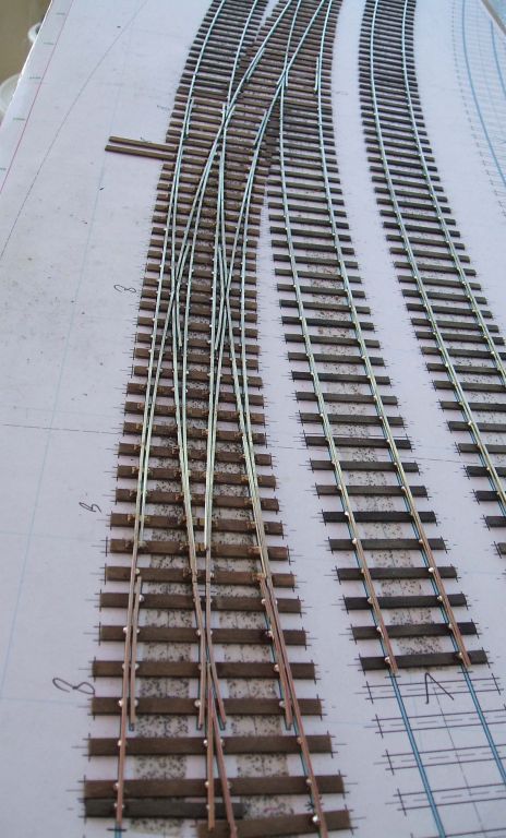 The critical area. 2151_061307_430000000.jpg 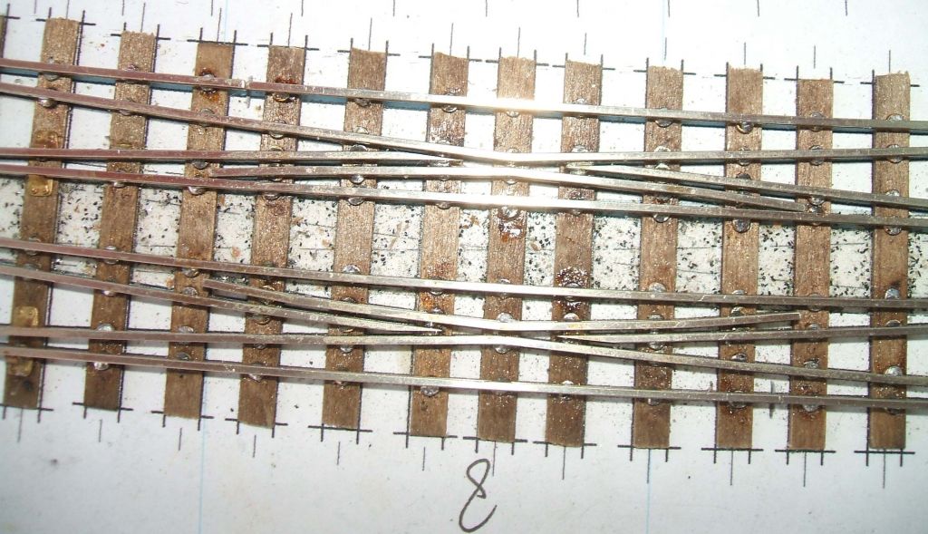 |
||
|
posted: 6 Aug 2019 18:59 from: Rob Manchester
click the date to link to this post click member name to view archived images |
Hi Tony, Do you have any experience in EM-SF with 0.8mm flangeways on diamonds or slips ? I have sort of adopted it as my standard now as it gives nice running with a visible flangeway that looks very close to P4 but you retain some cross running capabilities with normal EM. I have only done ordinary turnouts so far to test the water but at some point(!) will have to be dip into some more complex items, can't have a GW goods yard without a slip or two... Sorry to hijack your thread Andrew. Watching you as always - nice work, glad you enjoyed the modelling weekend. Rob |
||
|
posted: 6 Aug 2019 23:51 from: Andrew Duncan
click the date to link to this post click member name to view archived images |
Tony W wrote: Hi Andrew.Hello Tony It’s good to hear from you again, it’s been quite a while. Foolish or brave or just a bit naive? Not sure how I’d characterise my actions but as usual I stand in awe at the neatness and beauty of everything you produce and all in S4 to boot. However my question to you is why didn’t you switch the K crossings on the double slip in your photo which is clearly curved. Having met you once and read your Brimsdown thread religiously I have an idea, but would like to hear it from horses mouth. I am also interested in what you said about the gauge, but didn’t follow it entirely. When you said The track gauge at the center of the obtuse crossings needs to be absolute minimum and I set this to 18.0mm even when using 18.2mm gauge elsewhere to maximize the chance of success. How does this maximise the chances of success I emphasize the track gauge of each road NOT the minimum distance as measured directly between the knuckles centers. And this I’m afraid I didn’t follow at all. To show you that I am not a complete Neanderthal and am open minded I’m currently considering switching the K crossings on the single slip that on the main line that I’m about to commence battle with. Do you have any tips on the approach I might take with it. It’s a 1:8 on approximately a 3’6” curve. And last question for you. Have you made any progress on deciding on a tiebar format yet for Brimsdown? Kind regards Andrew |
||
|
posted: 7 Aug 2019 23:01 from: Andrew Duncan
click the date to link to this post click member name to view archived images |
Hello Rob Good to hear from you. Interesting that you've adopted a 0.8mm flangeway gap and if I may echo Tony's remarks about my slip, quite a brave thing to do. Do you narrow the gauge in point work to enable ordinary EM mm back to back to run through or is there sufficient slop to allow it to work unaltered? As it closes up the difference(between EM at 1.0mm and P4 at 0.68mm) by 60%+ it must look pretty good as well as running well through crossings. Do you have any photos? In fact at one stage I thought of bringing mine down to 0.9mm flangeway but didn't feel I really had the skills to pull it off. Even that small difference (10%) made some difference visually and quite considerably tightened up the look of common crossings. Ah well, time for we dram of something (out of a Riedel Cognac glass naturally) before turning in. Kind regards Andrew wow, Lydl's cooking brandy in the right glass... just like a glass of Remy Martin... |
||
| Last edited on 7 Aug 2019 23:13 by Andrew Duncan |
|||
|
posted: 7 Aug 2019 23:23 from: Martin Wynne
click the date to link to this post click member name to view archived images |
Andrew Duncan wrote: Hello RobHi Andrew, Rob's EM-SF standard is explained here (to which you replied): topic 3380 - message 26610 As far as I know, Rob is the only one using it (so far). cheers, Martin. |
||
|
posted: 7 Aug 2019 23:34 from: Jim Guthrie
click the date to link to this post click member name to view archived images |
Andrew Duncan wrote:
Andrew, Another trick I have tried with "K" crossings is to raise the check rail by a small amount which effectively extends the checking distance across the gap. Jim. |
||
|
posted: 7 Aug 2019 23:53 from: Martin Wynne
click the date to link to this post click member name to view archived images |
Jim Guthrie wrote:Another trick I have tried with "K" crossings is to raise the check rail by a small amount which effectively extends the checking distance across the gap.Hi Jim, The prototype does that too nowadays, for the same reason. It cause problems with any steam locomotives having flangeless drivers. Are there any of those in preservation? cheers, Martin. |
||
|
posted: 8 Aug 2019 00:40 from: Nigel Brown click the date to link to this post click member name to view archived images |
Martin Wynne wrote: Jim Guthrie wrote:Another trick I have tried with "K" crossings is to raise the check rail by a small amount which effectively extends the checking distance across the gap.Hi Jim, Cunning! Must remember that one. There are 3 operational 9Fs in preservation. Nigel |
||
|
posted: 8 Aug 2019 00:42 from: Rob Manchester
click the date to link to this post click member name to view archived images |
Martin, Oh no, don't say I am the only one using EM-SF There are several BR 9F's in working order but they are banned from main line running for just the reason you mention ( flangeless centre drivers ). The axles either side of the centre have reduced sized flanges too if I remember correctly. I have seen Evening Star on the mainline but it was a number of years back before the ban. One of the 0-8-0 goods tender locos that ended up as part of the LNER stock had one of the driving axles with flangeless wheels but I don't think there are any still around. Andy, Good to hear from you too. The key to EM-SF is the fact that the flangeway gap is less than the rail head width which is what the eye expects to see on real track. Use Templot and print out a #6 diamond in both normal EM and EM-SF. The track gauge of EM-SF is narrowed to 18mm on all track until gauge widening is required on the bends. As Martin will point out you do have to use wheels with narrow flanges ( Gibson, Ultrascale etc ) rather than re-gauged Hornby etc. Time to get my tumbler out............ Rob |
||
|
posted: 8 Aug 2019 01:05 from: Martin Wynne
click the date to link to this post click member name to view archived images |
Hi Nigel, Rob, Thanks for the info on preserved flangeless driving wheels. The only one I knew about was Gordon the Blue Engine: http://www.svrwiki.com/LMR_600_Gordon Which is currently in the SVR railway museum at Highley, and not looking to move far anytime soon. cheers, Martin. |
||
|
posted: 8 Aug 2019 06:04 from: Andrew Duncan
click the date to link to this post click member name to view archived images |
Martin Wynne wrote: Andrew Duncan wrote:Hello MartinHello RobHi Andrew, I’d completely forgotten about it, and it was only 8 months ago! Ah well, let’s hope things don’t go down hill too quickly after this. Kind regards Andrew |
||
|
posted: 8 Aug 2019 06:10 from: Andrew Duncan
click the date to link to this post click member name to view archived images |
Jim Guthrie wrote: Andrew Duncan wrote:Hello Jim Clever idea! Kind regards Andrew |
||
|
posted: 8 Aug 2019 06:24 from: Bernard Haste click the date to link to this post click member name to view archived images |
SBB (switzerland) has used raised check rails on the Brunig line (metre gauge) since at least 1984. Bernard |
||
|
posted: 8 Aug 2019 06:27 from: Andrew Duncan
click the date to link to this post click member name to view archived images |
Rob Manchester wroteAndy,Hello Rob You make an interesting point about the ratio of rail head width to the flangeway width. I’ll try a print out of one of my turnouts converted, but you know I dont really need much convincing, I’m sure it looks a great deal better. If you feel so moved at some point, a picture of a turnout built to the standard would be very interesting to see🤪 Kind regards Andrew |
||
|
posted: 8 Aug 2019 18:01 from: Tony W
click the date to link to this post click member name to view archived images |
Hi Rob. Not thus far. Not too sure about the proliferation of additional standards for EM and compatibility problems thus caused, but any reduction of the flangeway gap at obtuse crossings and in consequence the distance between the noses of the point rails should, other things being equal, help reduce problems. Regards Tony. PS I didn't realise your post was the last one on the previous page so is out of step with other replies. Oops. |
||
| Last edited on 8 Aug 2019 18:10 by Tony W |
|||
|
posted: 8 Aug 2019 18:53 from: Tony W
click the date to link to this post click member name to view archived images |
Andrew Duncan wrote: Tony W wrote: However my question to you is why didn’t you switch the K crossings on the double slip in your photo which is clearly curved. Having met you once and read your Brimsdown thread religiously I have an idea, but would like to hear it from horses mouth. Hi Andrew. The goods yard at Brimsdown was straight as was the pointwork. To fit in as much of the trackwork as I wanted in the available space, something had to give and I chose to compress the goods yard end of the layout and run some of the pointwork into the end curves, thus there is a large compromise in this area. C-7 crossovers morphed into E-16s and the 1 in 8 double slip became curved. By 1965 the goods yard was little used anyway and much of it lifted, so modellers license has been invoked to some extent. Regarding the geometry of the diamond, EM appears to have changed its standard gauge over time. I have two EMGS booklets on track standards. The earliest one states the track gauge as 18.0 mm, the later one as 18.2 mm. All the other important dimensions were unchanged. There is thus more side play with current standards than originally specified. This is undesirable at the middle of an obtuse crossing, which is why I use the 18.0 mm dimension. Incidentally I do something similar in P4 / S4 as the track gauges I have produce slightly over wide track. I use a Check rail gauge that measures 18.83 overall for this job. The distance between the middle of the bends in the opposite stock rails at the obtuse crossing will be greater than the track gauge due to both the bending of the stock rails and the geometry of triangulation of the crossing angle. As the angle increases (in degrees) the difference will increase. Consider a 90 degree crossing the most extreme case, the dimension across the corners will be root 2 or 1.414 x the gauge. For the mainline single slip, I would alter it in Templot and reprint it. The template will show you what you need to know. Filing the diamond switches is more akin to filing point or splice crossing rails except for the foot on the inside. No progress re the tiebars as yet. I have been busy recently planning and installing a new Kitchen, which is now almost finished. Regards Tony. |
||
| Last edited on 9 Aug 2019 18:22 by Tony W |
|||
|
posted: 11 Aug 2019 23:32 from: Andrew Duncan
click the date to link to this post click member name to view archived images |
Tony W wrote: Andrew Duncan wrote:Hello TonyTony W wrote: However my question to you is why didn’t you switch the K crossings on the double slip in your photo which is clearly curved. Having met you once and read your Brimsdown thread religiously I have an idea, but would like to hear it from horses mouth. Thank you for your very full answers. As purveyor of all things cookware I thoroughly approve of getting your priorities right. The kitchen is / can be/ should be, the heart of the home where food is prepared cooked and consumed suitably washed down, “tea with a fry up” and “a decent Bordeaux” īwith anything taken after 6pm. So very glad to hear you’ve not only installed your own kitchen but planned it as well. Doubtless with same attention to detail that you put into Brimsdown and other layouts before no doubt. I can’t pretend however to understand your geometry as I’m a visual person, failed maths O level completely and talk of roots just leads my thoughts to the garden. Perhaps if your going to be at Scaleforum you might draw me a diagram? I’m taking your advice , or rather I’m going to attempt to take it with the single slip (1:8) on the down main, and install moving K crossings on it. This evening I’ve been just planning how to do it and where to put loose heels ( I use 10 ba nuts and bolts to hinge you may recall) for both the slip switches and the mowing K crossings. In the picture the crosses mark the spot where I’m proposing to fit them, albeit the wood sleepers marked will be replaced with copper paxolin. 2787_111818_310000000.jpg 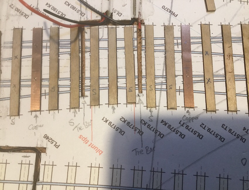 And I see that it difficult to see the crosses on the two paxolin sleepers. I have done a reprint of the slip for reference but having stuck the sleepers down on the original version with fixed K crossings, I didn’t feel like tearing them up, so bodged it by tipexing over the unnecessary check rails for clarity Kind regards Andrew |
||
|
posted: 12 Aug 2019 13:21 from: Tony W
click the date to link to this post click member name to view archived images |
Hi Andrew. The kitchen was a joint design between my wife and myself, She had the vision of what she wanted and I worked out how to make the best use of the available space, which was poorly utilized previously. As you may be aware, for bull head rail, the tips of the switches at the K crossing of a switched diamond are supported on the center timber by special wide slide chairs. This in turn requires a wider 14" timber. The full size distance between the ends of the blade tips is 4". 1.33mm in 4mm/ft scale and is not affected by the track gauge i.e. OO, EM or P4. I won't complicate the issue here with the Flat bottom arrangement, which differs. I shall be a Scaleforum both days as I am running a workshop, but you are welcome to drop by between sessions. Regards Tony. |
||
|
posted: 12 Aug 2019 20:24 from: Andrew Duncan
click the date to link to this post click member name to view archived images |
The Tony W wrote: Hi Andrew.Hello Tony I wasn’t aware of the necessity to have a wider timber in the middle of the slip, although it makes complete sense along with the wider chair. In fact I might have looked in my Switch and Crossing practice by David Smith but until you mentioned this I hadn’t. Well I have now. It turns out that the Great Western used 17” timber in this location until 1938 when they started to use two 12” timbers laid side by side. So for me it’s a 6mm wide timber with maybe two slide chairs slimmed down a bit to represent the extra wide slide chair you mentioned. The Smith book also mentions that in addition there is a supporting rail on the outer face for much of the length of the switch itself and that the switches themselves were of the flexible type not loose heeled as I’ve been modelling. Remembering that this is a single slip, as two of these four rails ( switches) are also stock rails at their common crossing ends I’m a little concerned that there won’t be enough flexibility in about 55mm of rail for a servo to push it over the moving elbows. And another thought reinforces this when I consider that unlike normal switches which have far less metal in them, the moving elbows are pretty well a full rail cross section for almost all their length. I’ve uploaded a copy of the relevant area of the slip I’m building in the hope that it all makes sense. And I’ve pencilled in the approx position of the support rails either side of the movable elbows. Alternatively page 53 of David Smiths book will make it clearer I suspect. 2787_121516_300000000.jpg 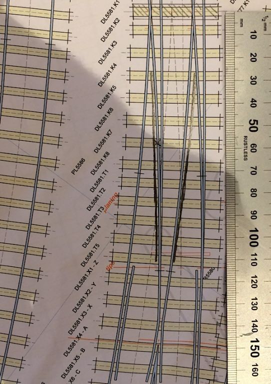 The X is the probable hinge point for the elbow and the lines either side are the lateral support rails which I have to confess I didn’t know existed before now. Kind regards Andrew |
||
| Last edited on 12 Aug 2019 20:25 by Andrew Duncan |
|||
|
posted: 13 Aug 2019 16:08 from: Tony W
click the date to link to this post click member name to view archived images |
Hi Andrew. You may find this picture useful. It appears GWR. You have answered one of my questions as to what the additional pieces of rail were for. 2151_131059_030000000.jpg 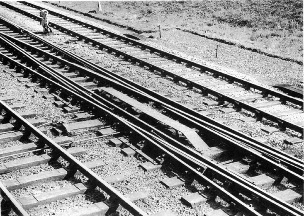 There is much detail here, the wider and longer center timber is obvious. There are also locking bars visible. Regards Tony. |
||
|
posted: 14 Aug 2019 06:22 from: Andrew Duncan
click the date to link to this post click member name to view archived images |
P Tony W wrote: Hi Andrew. Thanks very much for the photo Tony. Two questions spring immediately to mind. Firstly would they have had facing point locks in the Yeovil scenario as crossing from Up line to Down would have involved only goods stock or maybe empty coaches? Secondly in the photo, the support rails either side of the switches are very short. In the David Smith book they are represented as going most of the way to the common crossing. What was the logic that they applied here I wonder. Maybe the Yeovil situation demanded full length support ( to the common crossing) as it was on a sharpish curve? Any informed thoughts would be gratefully received. Andrew |
||
|
posted: 14 Aug 2019 15:40 from: Tony W
click the date to link to this post click member name to view archived images |
Hi Andrew. I think this may be one for the experts. This is the only picture I have come across showing such additional rails and I wondered what their purpose was, a question you have answered. As far as I can tell these support rails are bolted to the switch rails at the first fixed chair only. What other means of support they have I cannot say, but I suspect special chairs are required. It would certainly make sense to employ longer support rails for curved trackwork where the side forces would be greater. You are probably correct about the facing point lock situation. It is my understanding that FPLs were only mandatory for passenger carrying lines, but that does not necessarily exclude their use in other situations. Regards Tony. |
||
| Last edited on 14 Aug 2019 15:45 by Tony W |
|||
|
posted: 14 Aug 2019 16:07 from: Martin Wynne
click the date to link to this post click member name to view archived images |
Tony W wrote: Hi Andrew.Hi Tony, David Smith's GWR track book has a detailed description, page 55. The GWR regarded the switches in a switch-diamond as very similar to ordinary switches, the reinforcing rails being the stock rails, with similar fixings and slide chairs. The switch rails were flexible, not loose-heel, and 32ft long (as the 30ft straight switches). But unlike other GWR switches, they were undercut rather than joggled, it being impossible to provide a joggle in the K-crossing wing rails. The reinforcing rails were normally much longer than in your photo, almost the full length of the switch rail. Your photo is unusual. Also the adzing of the sleepers in the foreground is puzzling. cheers, Martin. |
||
|
posted: 14 Aug 2019 16:21 from: Tony W
click the date to link to this post click member name to view archived images |
Hi Martin. Unfortunately David Smiths book is not part of my collection and I don't recall now where I found that picture or where it was taken. I think if I were in Andrew's situation, I would follow the book rather than the picture. If it were taken on a preserved line anything is possible. Regards Tony. |
||
|
posted: 14 Aug 2019 16:36 from: Martin Wynne
click the date to link to this post click member name to view archived images |
Tony W wrote: Hi Martin.Hi Tony, A lot of the chairs visible seem to be of slab & bracket design, which is not the original GWR design. This might be a later BR(W) revised version. It is interesting to see the reversing crank in the rodding on the extended middle timber. A detail worth modelling. cheers, Martin. |
||
|
posted: 14 Aug 2019 18:14 from: Rob Manchester
click the date to link to this post click member name to view archived images |
Tony W wrote: Hi Martin.Hi Tony, The cheapest one available at present is this one Well worth it in my view for the design insights it gives. Your view may vary. Rob |
||
|
posted: 14 Aug 2019 18:38 from: Martin Wynne
click the date to link to this post click member name to view archived images |
Rob Manchester wrote:The cheapest one available at present is this oneHi Rob, Still listed new from the GWSG: http://gwsg.org.uk/GWSG_Publications.html Is that wrong or out of stock? I agree it's an essential read for anyone interested in track, even if not GWR or in 4mm scale. cheers, Martin. |
||
|
posted: 14 Aug 2019 18:42 from: Rob Manchester
click the date to link to this post click member name to view archived images |
Hi Martin, Yes, forgot that source. May be worth Tony emailing them to check if available. Rob |
||
|
posted: 14 Aug 2019 22:15 from: Nigel Brown click the date to link to this post click member name to view archived images |
GWSG are usually pretty good at noting items out of stock. It does appear to be available and cheaper than the Amazon version. I agree, it's an excellent investment. I'm counting my pennies to see if I can afford their new GWR signalling book. Nigel |
||
|
posted: 15 Aug 2019 10:11 from: Graham Idle
click the date to link to this post click member name to view archived images |
Andrew, I have a copy of this which I would be happy to lend to you if you would like. Regards, Graham Idle |
||
|
posted: 15 Aug 2019 11:17 from: Andrew Duncan
click the date to link to this post click member name to view archived images |
Graham Idle wrote: Andrew, I have a copy of this which I would be happy to lend to you if you would like.Hello Graham That s very kind of you to offer but in fact I do have a copy, and it’s Tony who doesn’t have one. And despite having read it several times I’m still finding it hard to get my head around all the nuances of this piece of point work, not least because I don’t have any photos of that far end of the station. At present I don’t even know if in reality they did.use moving K crossings or fixed ones? Anyway thanks again for the offer. Kind regards Andrew |
||
|
posted: 15 Aug 2019 16:05 from: Graham Idle
click the date to link to this post click member name to view archived images |
Andrew Duncan wrote: Graham Idle wrote:No problem Andrew, I too find pointwork bewildering at times.Andrew, I have a copy of this which I would be happy to lend to you if you would like.Hello Graham Regards, Graham |
||
|
posted: 17 Aug 2019 11:05 from: Andrew Duncan
click the date to link to this post click member name to view archived images |
Martin Wynne wrote: Tony W wrote:Hello MartinHi Andrew.Hi Tony, Thanks for your reply and knowledge of these things. I’ve attached a photo of my proposed plan of how I’m intending to build it. It’s not clear to me on page 55 whether the slip switches ( as opposed to the moving elbows) were loose heeled or not. As I said previously in the thread I’m concerned that there won’t be enough flexibility in the rail if I don’t hinge them ( nut and bolt). But it’s also true I haven’t built a conventional switch in years and so I’m not really familiar with how flexible fixed heel blades can be? Am I worrying unnecessarily? In any case which is the correct approach for the slip switches, fixed or loose heel? This is the complete slip with ordinary chairs and slide chairs marked along with the extra support rails as well. In the photo I’ve forgotten to extend the centre timber onto which I’ll need to build some semblance of the reverse crank. 2787_170545_330000000.jpg 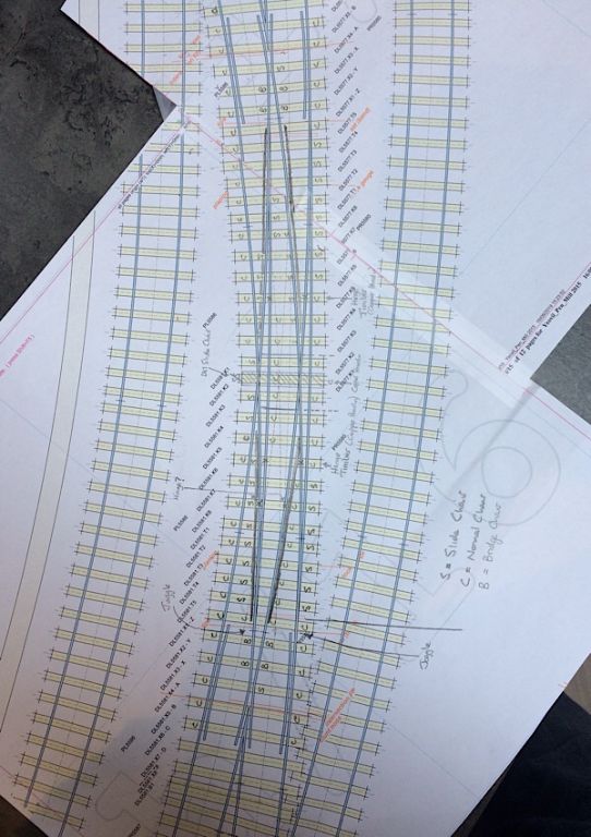 Kind regards Andrew |
||
|
posted: 17 Aug 2019 11:48 from: Martin Wynne
click the date to link to this post click member name to view archived images |
Hi Andrew, Page 57 says all slip switches in GWR compounds (GWR-speak for slips) were old-type loose-heel switches (hinged). So if you happy building such, I would go ahead and do the same. However, page 55 says the moving K-crossing switches (movable elbows) were long flexible switches. I see you have marked them to be hinged. I think they would be sufficiently flexible if you made them solid. They need to fixed where they are forming the stock rails for the slip switches, but beyond there they can be flexible (unless your point-motors are more feeble than most -- will you be using two of them for the K-crossings, or just one with a rocking crank, as the prototype?). cheers, Martin. |
||
|
posted: 17 Aug 2019 13:13 from: Tony W
click the date to link to this post click member name to view archived images |
Hi Andrew. My bible tends to be British Railway Track published by The Permanent Way Institution since most of my track is of the REA type. This lists the types of special chairs required for switched diamonds, but does not give a list of how many of each type, unlike turnouts. These are of the sprung, fixed heel type only. The few switched diamonds I have built, I have allowed a couple of extra slide type chairs to increase the flexibility. However this will be academic for you as you will be using loose heel switches. (I do have other track publications in my library though, just not that one.) Regards Tony. |
||
| Last edited on 17 Aug 2019 13:16 by Tony W |
|||
|
posted: 17 Aug 2019 13:58 from: Andrew Duncan
click the date to link to this post click member name to view archived images |
Martin Wynne wrote: Hi Andrew,Hello Martin Thank you and yes I’m very happy to build them with hinged heels, which is how all my turnouts ate constructed. And no I’ll be using two servos on the knuckles one on each pair although I’m now thinking that I can probably put the tie bars in their prototypical position immediately either side of the centre timber, not as I’ve drawn it, ( one timber removed from that position). The servos are the normal 9gm ones, so no not especially weak I’d say. Thanks for your help. Kind regards Andrew |
||
|
posted: 17 Aug 2019 14:09 from: Andrew Duncan
click the date to link to this post click member name to view archived images |
Tony W wrote: Hi Andrew.Hello Tony Yes understood and thanks for your experience on moving knuckles. As you can see from Martin’s advice and my reply to him it looks like slips are mongrels when it comes to the types of switch employed. Fixed hinge for the knuckles and loose heeled for the slip roads! Thanks again for your help and practical experience. Kind regards Andrew |
||
|
posted: 25 Aug 2019 10:53 from: Andrew Duncan
click the date to link to this post click member name to view archived images |
So progress has been a bit slow recently but I have now cut the channels for control wires for the K Crossings ( moving elbows, I don’t know which is the correct terminology). And have run brass 0.4mm wire through them In readiness to connect them to the tie bars and servos at the back of the baseboard. Whilst talking channels in the baseboard surface; this time I’ve installed tubes for all the surface mounted wiring to make it easier to terminate the wire, particularly when attaching to the rail sides. If I get it wrong I can pull through a bit of extra wire. This is an idea I got from Tim at Missenden a few weeks ago. A clever simple idea that I hadn’t thought of. Another benefit of going to these things particularly for a lone modeller. So here’s a photo of the centre of the slip showing the loose heeled switch hinges / nuts soldered to the underside of the sleepers just before sticking in position, and the 17” wide central timber, extra long to take the operating crank, which I’ll build in when installing the point rodding. These loose heels are for the slip switches, the K Crossings are not loose heel so don’t require any hinge. 2787_250523_270000000.jpg 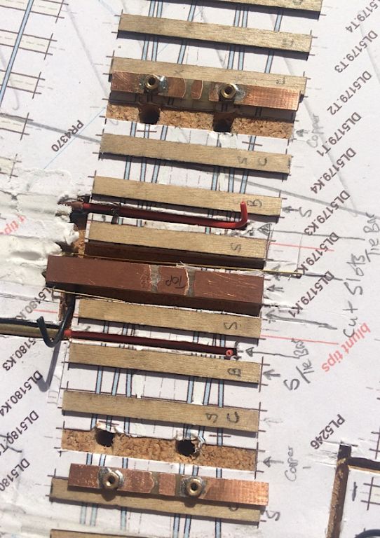 2787_250532_550000000.jpg 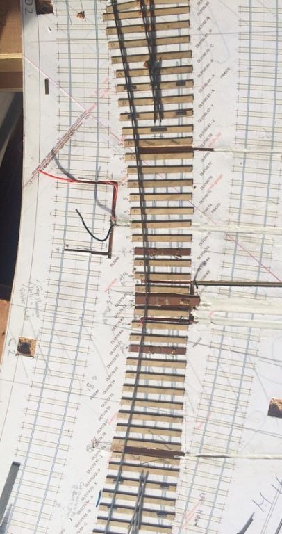 And here’s the complete slip with all the sleepers in place and the first rail bent to the right shape as far I could manage, to reduce the stress and just laid in place to see how it follows the curves. You can also see the short lengths of tinned brass strip super glued to the timbers in places of potential mechanical stress such as the check rails and the centre of the slip itself. EDIT oops sorry no couldn’t because the K crossing ones weren’t in that photo, but here they are now. 2787_251032_120000000.jpg 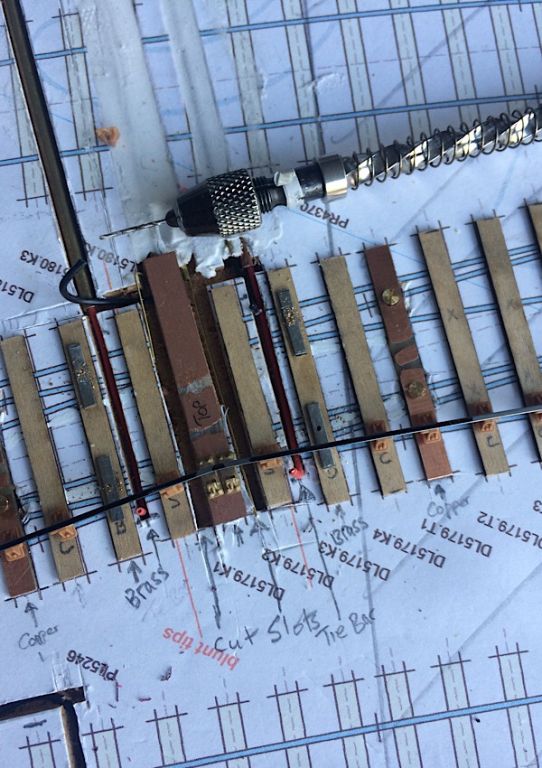 Incidentally I found that in building the double slip it was tricky not having these strips more securely tied to the sleepers ( heat easily breaks the bond of superglue) so this time I’m borrowing half an idea from Howard Bolton and am going to drill and pin them in place so that at a key moment of soldering, the whole thing doesn’t move in relation to the sleeper. No guesses as to how I know this can happen! Kind regards Andrew |
||
| Last edited on 25 Aug 2019 15:36 by Andrew Duncan |
|||
|
posted: 27 Aug 2019 05:35 from: Andrew Duncan
click the date to link to this post click member name to view archived images |
All these moving K crossings / Elbows are a new experience for me. In one way simpler because there are no check rails in the centre as there were with double slip I built a few weeks ago ( or the diamonds I’ve built before) but more complex thinking things through. For example two of the four moving elbows have to be exactly the right length to finish in the centre of the Single Compound ( GWR terminology for a single slip) and at the same time these two are the stock rails for two of the four switch blades at the outer ends of the slip, so requiring joggles. This is further complicated by the support rails that the GWR used strapped to the outside of each elbow. These I will be including but are not present in the photo below. Surprisingly despite the great weather this weekend, much of it spent pottering in the garden I managed to temporarily lay out some of centre of the slip including one of the moving elbows correctly in place and it looks like it might all line up ok. Another surprise if I’m right! So here you can see (at the bottom of the photo ) the elbow is snuggly up against its Stock Rail (?) whereas the one opposite ( above in the photo) is sitting just a touch proud of the rail that it’s abutted to, but enough I expect to derail anything travelling over it. I realise, looking at this photo, how Heath Robinson my modelling looks as. Hopefully once sprayed and ballasted, it’ll look the part? 2787_270008_270000000.jpg 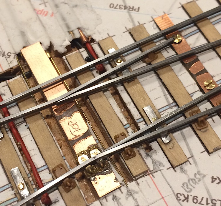 Later I’ll try to upload an image that illustrates my point about the other end of the elbow rail near the crossing with its joggle Andrew |
||
| Last edited on 27 Aug 2019 07:48 by Andrew Duncan |
|||
|
posted: 28 Aug 2019 22:26 from: Andrew Duncan
click the date to link to this post click member name to view archived images |
And here’s a rather poor photograph of the whole slip with one of the four support rails laid alongside it albeit with a bit too much gap between it and the rail it’s meant to be supporting and that rail which a flexible switch at one end and a stock rail at the other, actually has the toggle already formed but it’s rather difficult to see. 2787_281713_550000000.jpg 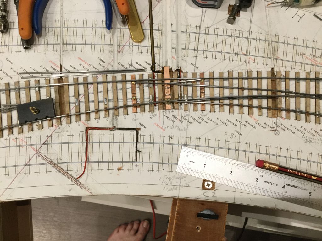 |
||
|
posted: 30 Aug 2019 17:04 from: Tony W
click the date to link to this post click member name to view archived images |
Andrew Duncan wrote:
Hi Andrew. The lower switch blade looks fine to me, but as you rightly state, the upper one needs some attention. It is too long and overlaps the center of the bend in the stock rail. The tip is also too thick. If you can duplicate the fit of the lower switch rail with the other three I don't foresee any great problems with the running. Regards Tony. |
||
|
posted: 30 Aug 2019 23:25 from: Andrew Duncan
click the date to link to this post click member name to view archived images |
Tony W wrote: Andrew Duncan wrote:Hello Tony Thanks for your thoughts on the switch blades and I’m interested in your observations of the upper blade being too thick. I’m using steel rail and as I produced this one in the Scalefour society jig, I went a touch too far and filed too much off leaving the centre web very thin (foil like), I tried repairing it by filing back the point to get to more solid rail but maybe went a bit far and as a result have too blunt a nose. But here my question to you is, how different is this point ( on a moving K crossing) to the blunt nose of a common crossing, which really is quite blunt? Should it be rounded off reduced in height by a smidgen as with a common crossing, or am I barking up the wrong tree? I mentioned the rail being steel as I’ve been dipping in and out of your treatise on turnout construction over on E4rum, which is excellent by the way, and noticed your comments about steel being less forgiving in this sort of situation. Kind regards Andrew |
||
|
posted: 30 Aug 2019 23:41 from: Andrew Barrowman
click the date to link to this post click member name to view archived images |
Hi Andrew, Is the copper-clad timber with the brass screws made from single or double-sided copper laminate? No problem if it's single-sided but if it's double-sided both top and bottom need an insulating gap to prevent the screws creating an invisible and typically intermittent short circuit. Cheers! Andrew |
||
|
posted: 31 Aug 2019 06:07 from: Andrew Duncan
click the date to link to this post click member name to view archived images |
Andrew Barrowman wrote: Hi Andrew,Hello Andy That’s a good question and you are quite correct to observe that it’s double sided copper clad that the brass nuts are soldered to. Ideally I’d have found some single sided of the right thickness but haven’t had any for a while now. So I do gap them on both sides. In fact I double gap them on both sides and avoid gaping at the same point on the timber top and bottom to avoid weakening them too much. An idea I learnt from Howard when making my latest style of tiebar a few pages back. Another thing I’ve tried is rather than cut the copper with a razor saw or a file, I use an abrasive stone in a Dremel to do the job. It just sort of wears away a strip across the timber which when painted is less noticeable than a fine cut I think. I also run the stone down both edges to make sure I haven’t got a thin invisible line of copper left hiding there. Then test electrically with meter. I’ve had too many short circuits to take chances on this. Equally I’ve quite frequently got to the testing stage and found I’ve forgotten to do any of the above! Very trying. Thanks for the question. Kind regards Andrew |
||
|
posted: 31 Aug 2019 10:18 from: Hayfield
click the date to link to this post click member name to view archived images |
Andrew Do you file an angled bevel on the top of these switch rails? I also find just putting a slight curve on the top angle of the point on the switch blade helps |
||
|
posted: 31 Aug 2019 10:38 from: Andrew Duncan
click the date to link to this post click member name to view archived images |
Hayfield wrote: AndrewHello John If you're referring to this particular moving K crossing switch, then this is the first time I've made them so I don't have previous experience with them other than what I describe in my reply to Tony yesterday, I haven't done anything else in terms of shaping. If I think of what I do when constructing a fixed diamond then no I don't do any shaping at all, but maybe I should have treated it rather like a turnout switch blade...? Kind regards Andrew |
||
|
posted: 31 Aug 2019 11:25 from: Hayfield
click the date to link to this post click member name to view archived images |
Andrew Do you file an angled bevel on the top of these switch rails? I also find just putting a slight curve on the top angle of the point on the switch blade helps |
||
|
posted: 31 Aug 2019 20:54 from: Andrew Barrowman
click the date to link to this post click member name to view archived images |
Andrew Duncan wrote: Andrew Barrowman wrote:Hi Andrew,Hi Andrew,Hello Andy Looks like you have it covered! I'd forgotten you solder nuts on the underside, so that timber must be double sided. I use a similar technique to remove a wide section of copper. It's much less obvious than a saw cut. I do it with the edge of a cutoff wheel rather than an abrasive stone. Cheers, Andy |
||
|
posted: 1 Sep 2019 06:37 from: Andrew Duncan
click the date to link to this post click member name to view archived images |
Andrew Duncan wrote: Hayfield wrote:Hello JohnI hope I’ve answered your question above. Seems to have come through twice?AndrewHello John Andrew |
||
|
posted: 1 Sep 2019 12:18 from: Andrew Duncan
click the date to link to this post click member name to view archived images |
Andrew Barrowman wroteHi Andrew,Let’s hope so! Another couple of pictures here to show you what I did last night and first thing this morning. Well blow me down I’ve got the gauge correct through the middle of the slip with very little in the way of reference points! Time for a glass of something? Well perhaps not as it’s before the sun hits the yard arm, so I’ll make do with a coffee and slice of panettone, buttered of course. Very satisfying (Edit) Actually having congratulated myself on getting the gauge correct through the middle I’m now a bit concerned at the gap opening up to the left hand end of the gauge. I’m hoping that that’s because the whole thing is on a sharpish curve, about 3’6” from memory. Better take a look at it with the mirror to see if I’ve got a misalignment somewhere there? 2787_010648_370000000.jpg 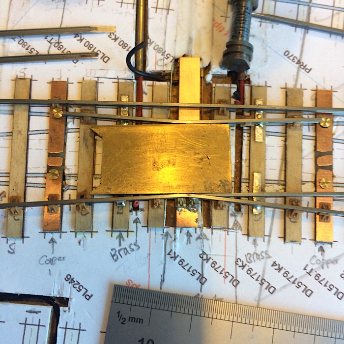 And here’s the “odd”support rail ( the one with the dotted black line) shoved roughly in place to give me an idea of how it will fit and how I’m going to fix it, probably soldered to the brass strips and then slide chairs cut and extended in length enoug to still stick out the other side of the K crossing switch to do their job properly of supporting said switch. Difficult to describe so I’ll post a photo when I’ve done it. 2787_010654_490000000.jpg 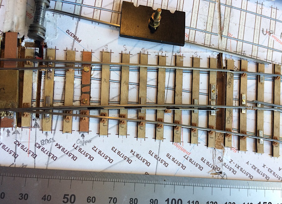 And lastly a photo close up of the “odd” support rail where finished close to the K crossing. I shall be tempted to make this gap a 1mm one but suspect it’ll end up being a bit more to not catch wheel flanges passing by. Well see! 2787_010706_390000000.jpg 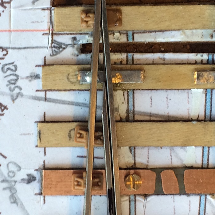 Ok, sad though this may sound, this is getting rather exciting. It’s every bit as challenging as the double slip was and I’ve a feeling it’ll work a lot better if I can only get the subtle curves right and switches a snug fit. Kind regards Andrew |
||
| Last edited on 2 Sep 2019 07:18 by Andrew Duncan |
|||
|
posted: 2 Sep 2019 09:55 from: Hayfield
click the date to link to this post click member name to view archived images |
Andrew Duncan wrote: Andrew Duncan wrote:Andrew It was just a thought, I am with you on a fixed diamond, but then they do not move. I just thought as you are taking the tips right up to the bend it may help smooth the travel over the crossing outHayfield wrote:Hello JohnI hope I’ve answered your question above. Seems to have come through twice?AndrewHello John |
||
|
posted: 2 Sep 2019 10:02 from: Hayfield
click the date to link to this post click member name to view archived images |
Andrew Duncan wrote: A thought over copperclad timbers and sleepers, I make a shallow cut with a hacksaw to break the copper foil, I mix up some Green Squadron filler with liquid poly (to make it very runny). Leave it 24 hours to set hard, then file flat. When painted the cut is invisible I tried using a razor saw to cut the gaps, but current jumped the gap, hacksaw blade width cut is fine |
||
|
posted: 2 Sep 2019 18:26 from: Rob Manchester
click the date to link to this post click member name to view archived images |
Andrew, John, I use a small round sanding drum in a mini drill to 'gap' the pcb. I aim to remove the copper over a width of maybe 8-10mm on straight track size sleepers and make sure the gap tapers very gently towards the ends so there is no visible step in the sleeper surface. No filler is needed - just paint the sleeper in the normal way. In tight situations around crossing work you need to plan ahead and make the gaps before all the rails are in place. Rob |
||
|
posted: 2 Sep 2019 23:10 from: Andrew Duncan
click the date to link to this post click member name to view archived images |
Hayfield wrote: Andrew Duncan wrote:Hello JohnAndrew DuncanAndrew It was just a thought, I am with you on a fixed diamond, but then they do not move. I just thought as you are taking the tips right up to the bend it may help smooth the travel over the crossing out Ok I’m with you now and I think you may well be right. I’ll give it try! Kind regards Andrew |
||
|
posted: 2 Sep 2019 23:24 from: Andrew Duncan
click the date to link to this post click member name to view archived images |
Hello Rob and John For some reason the thought of using filler and then sanding down seems pretty extreme to me. Not sure why I can cheerfully say that, and in another breath be soldering little brass nuts to the underside of sleepers to make loose heel hinges, which might also be construed as a little over the top! To each his own? But anyway with this you probably tell I'm closer to Rob’s suggestion although I think my current approach is pretty similar and fairly unobtrusive. Hadn’t thought of removing it over wider area though? Thanks for all your feedback and ideas, much appreciated as always. Kind regards Andrew |
||
|
posted: 3 Sep 2019 09:42 from: Hayfield
click the date to link to this post click member name to view archived images |
Andrew Duncan wrote: Hello Rob and JohnAndrew One of the great things about building your own track is the variety of methods at our disposal, as for loose hinges, I follow a method shown to me by I think Norman Solomon, which os to use cast brass fishplates, soldering one joint only As for sanding PCB strip, I am with you when the PCB strips are in situ, however with a bit of pre-planning it takes seconds to a a dollop of filler, then once set hard seconds to file flat. I guess its far easier to sand off the copper foil before adding the sleeper/timber to the item being built Other fixings that I do nor see used often are cast chairs, especially when used in conjunction with plastic chairs with plastic chairs |
||
|
posted: 4 Sep 2019 21:44 from: Tony W
click the date to link to this post click member name to view archived images |
Andrew Duncan wrote: Tony W wrote:Hi Andrew.Andrew Duncan wrote:Hello Tony You need to treat the moving K blades as very short switch blades and file them accordingly rather than a crossing nose. Having said that, you will of course be using the crossing filing jig to produce the required angle, but you do not need to file the whole height of the blade tip to a razors edge. The important area is the running head and this does need to be filed down to a very fine width at the tip in order to pick up an oncoming wheel without the flange hitting it. So just thinning down the top edge is all that is really needed for the final stage. I try to leave the foot on the inside of the switch rail, short though it is for added strength. I will see if I can find you a picture to illustrate this. The fun bit, as you have discovered, is forming the curves in switch rails to produce an even curve whilst maintaining the track gauge. Because of the curve, I would expect the mint gauge to run out to some degree as it does in your picture. Regards Tony. |
||
|
posted: 4 Sep 2019 23:05 from: Andrew Duncan
click the date to link to this post click member name to view archived images |
Hayfield wrote: Andrew DuncanHello JohnAndrewOne of the great things about building your own track is the variety of methods at our disposal, as for loose hinges, I follow a method shown to me by I think Norman Solomon, which os to use cast brass fishplates, soldering one joint only Yup I agree there so often a number of different approaches to building track as there are with so many things in life. I rather like the sound of the caste fishplate idea, quite prototypical. How do you get the power feed to the switches themselves or can you rely on the fishplate to give reliable contact? Thanks again for your ideas. Kind regards Andrew |
||
|
posted: 4 Sep 2019 23:15 from: Andrew Duncan
click the date to link to this post click member name to view archived images |
Tony W wrote: Andrew Duncan wrote:Hello TonyHello TonyHi Andrew. Thanks for your guidance on this. I’ll make the tip as fine as practicable and suck it and see! I’ll report back as soon as I’ve got a result! Kind regards Andrew |
||
|
posted: 5 Sep 2019 09:49 from: Hayfield
click the date to link to this post click member name to view archived images |
Andrew Duncan wrote: Andrew Usually I like to bond the switch rails to the stockrails to aid electrical conductivity, but with this method at least you have 2 places of contact, being the fishplate and the tip of the slide rail touching the stock rail. If I have used the timber under the tip of the switch rail by using a copperclad timber and a cast slide chair (slide plate cut away from the chair and soldered to both the timber and switch rail) that gives a third point of contact. For belt and braces a dropper wire could be attached to the switch rail close to the fishplate to under the base board, just ensure its quite thin/flexible I quite often think we do not make enough use of the cast rail parts in track building, going in some cases for exocitc rather than a simple solution |
||
|
posted: 7 Sep 2019 23:49 from: Andrew Duncan
click the date to link to this post click member name to view archived images |
Hello John Thanks for your thoughts on loose heels. Like you I think I’d always put some positive connection in for the electric feed. I take a wire off the bottom end of the brass bolt which the switch hinges on. I made a bit a progress today. Soldered up a pair of switches at one end of the slip and installed the “odd” support rail beside them. One or both may actually need removing and shortening if the flanges just catch their tips. I hope the photo makes clear what I’m referring to. The bit I’m concerned about is towards the top of the photo just below the moving elbow. The support rail stops just short of the elbow but leaving only a 1mm gap for the wheel flange to squeeze past. theoretically this should be enough but I’m not sure my track making skills are consistent enough to make that work. When I’ve assembled the switches for the other end of the slip and I can run my test wagon through I’ll know whether I’m better than I thought, or it’s time to take them out and shorten then a tad to open up the gap. 2787_071823_520000000.jpg 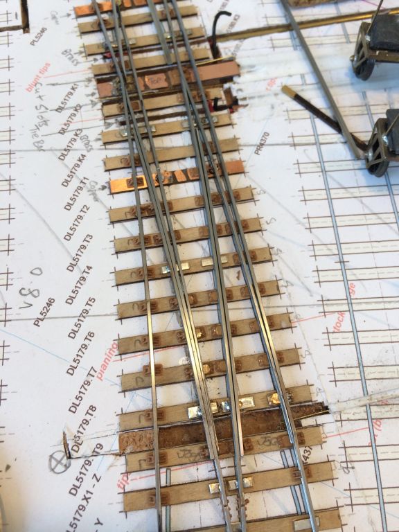 , ,Looking at this photo John I’m wondering if I’ve missed a trick ( as you were saying in your previous post) in not using brass slide chairs more, either pinned to the timbers or soldered to copper paxolin timbers down the middle of the slip where I’ve put brass strips. It would have been neater and stronger to use them rather than brass strips that have to be shortened and half chairs glued in place to disguise their presence. Live and learn but I’m not about to take it all out and start again! Kind regards Andrew |
||
|
posted: 17 Sep 2019 09:44 from: Hayfield
click the date to link to this post click member name to view archived images |
Andrew Sorry for the delay in replying, but been away in Italy on holiday. Quite often we become slaves to what we are used to rather than explore other methods. Many shy away from cast brass chairs and fishplates, presumably due to their cost. If used sparingly they add little extra to the overall cost. Same with using copperclad timbers either with ply of plastic timbered units, once painted they will not be noticeable, but the benefits are well worth breaking with convention Wagons whilst being very convenient to use in testing may not be as demanding as a six coupled chassis, I think Norman uses a free rolling loco chassis for testing, certainly I try to use a powered chassis as soon as practicable (using crock clips on power leads and jumper cables etc) I must admit to missing the relevance of the support rails, perhaps using a bit of modellers licence with their length may solve the issue |
||
|
posted: 21 Sep 2019 16:07 from: Andrew Duncan
click the date to link to this post click member name to view archived images |
Hayfield wrote: AndrewHello John Yup it’s human nature to stick with what we know and either deliberately not look elsewhere or just forget to. I know your right to point out that a wagon doesn’t really test track work like a long wheelbased tank loco, a pannier being a good example. So I shall remember to test it just as soon as I can under power with my one EM gauge loco. All the others are still in 00! As to the support rails either side of the flexible switches I’m either why they put in the support rails. Was it because they would otherwise have used loose heeled switches which I seem to understand we’re shorter and so had less unsupported length. But with the longer flexible switches they perhaps felt extra support was necessary? Kind regards Andrew |
||
|
posted: 22 Sep 2019 11:08 from: Hayfield
click the date to link to this post click member name to view archived images |
As for what type of wagons and locos to use, I have found long wheelbase vans to be more critical than standard wheelbase wagons, but I still use the latter. Also with locos it seems how much side play the chassis have also determines how they perform When building 00 gauge turnouts and crossings I have an old Mainline 0-6-0 chassis where all three axles have differing back to backs. Ideal test loco as it this loco works anything will !! Keep up the good work as I am enjoying the thread |
||
|
posted: 22 Sep 2019 17:45 from: Andrew Duncan
click the date to link to this post click member name to view archived images |
Hayfield wrote: As for what type of wagons and locos to use, I have found long wheelbase vans to be more critical than standard wheelbase wagons, but I still use the latter. Also with locos it seems how much side play the chassis have also determines how they performHello John Yup your right to remind me about long wheel base wagons as a greater test...time to convert a Toad me thinks! As to locos I always make sure the slack is non existent on front and rear wheels and plenty on the middle pair ( something Iain Rice taught me when showing me how to build a decent chassis) and that they can slide really easily from side to side. I’m guilty of having pretty slack coupling rods as well to aid this free running, but the benefit is very smooth running, no “ dot and carry one” here! (A Rice-ism) And they can negotiate pretty tight curves and horrible track as well! I like the idea of varying back to backs. Reminds me of Len Newman and “go” “no go” back to back gauges. And lastly John thanks for the encouragement, I’m glad your enjoying it. Kind regards Andrew |
||
|
posted: 29 Sep 2019 03:19 from: Andrew Duncan
click the date to link to this post click member name to view archived images |
Hello everyone I was at Scaleforum yesterday and was impressed once again with the standard of demonstrators. In a track context Tony Wilkins and Phil Tattershall we’re there teaching people (3 at a time) how to make Crossings and Switches blades respectively. It was in talking to Phil quite a few years ago, when he was demoing track making, that I finally decided to have a go at track making and whilst I was at it convert to EM from 00 and learn how to use Templot, and go it alone without expert help from Iain Rice who’d built much of my original point work for Maiden Newton and Yeovil Mk1. Sorry about the long sentence! And Tony was doing a very practical and encouraging approach to building really accurate crossings which I always find the hardest part of any turnout to build consistently. I certainly owe a lot to people like them for the kind, patient and non judgmental approach they take to their hobby which allows me to feel comfortable asking “silly” questions and being rewarded with clear explanations that allow me to improve little by little. Invaluable and ultimately very rewarding. Thanks chaps. As a matter of interest the Great Western Study group / David Smith have just brought out a fascinating tome on Great Western Signaling Practice which I just couldn’t resist despite its quite hefty price tag and having dipped into the first dozen or so,pages when I got home, I think this going to be a really good informative well illustrated read. Well done Mr Smith and the GWSG. I managed not to buy anything on the bring and buy stand despite a vey tempting Blacksmith Dean Goods, one of my all time favourite locos. But I still have in my pile under the bench, a Finney one to build which I shall do, with a bit of modellers licence, in original round topped firebox form, which makes them look even more elegant than the later and more time appropriate Belpaire type. Back to track work briefly, John’s( Hayfield) contribution last week got me thinking a bit more about the selective use of brass chars and in particular that of slide chairs and the inherent weakness in model form that they introduce into turnout construction. Its all very well soldering the slide chair to the rail but then supergluing it to the sleeper seems a bit of a bodge. So I thought I’d reinforce it by pinning it through the sleeper. As result last week I found myself drilling a minute hole (0.6mm) in the slide chair base, counter sinking it to take a pin head flush to the working surface and sat back somewhat amused and mystified at myself! I’m an EM modeller for heavens sake not a P4er. I’m a “broad brush stroke” sort of bloke and here I am drilling tiny holes in tiny brass castings that I can barely see. Have I really taken leave of my senses? Well I don’t know but I did get certain satisfaction out of it despite the fact that I later thought that, had I planned ahead, I could have used copper paxolin sleepers and soldered the whole thing up solid with the touch of my soldering iron. Strange what our hobby does to us sometimes....? Here’s a photo of my mad moment. Kind regards from lunatic asylum.... 2787_282209_580000000.jpg 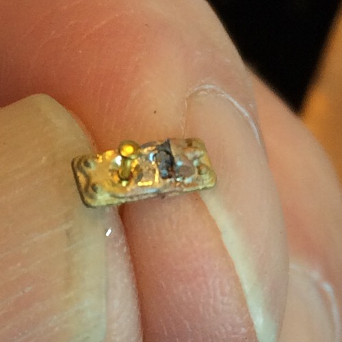 Andrew |
||
| Last edited on 30 Sep 2019 14:56 by Andrew Duncan |
|||
|
posted: 30 Sep 2019 08:40 from: Hayfield
click the date to link to this post click member name to view archived images |
Andrew What a good idea, especially when retrofitting. An Idea which needs testing, but may save a bit of time could be to glue rather than pin chairs. I was talking to a Canadian customer not only about soldering brass chairs.fishplates whilst building track but also the use of certain glues Over the past two years, but not the older type but the range of newer glues Last year after running out of what was my favourite thin superglue (well known brand from DIY stores & supermarkets) I was introduced to an industrial grade which is far stronger. Whilst having a kitchen fitted as well as new double glazing both sets of fitters used a mitre bond product (the stuff which you use an activator with) also a modern glue I guess like No More Nails (I use Extreme by Schtuk) In using for the purpose we require we just need something which is not degraded by heat. Well its an idea that might save a bit of time I liked the piece of trackwork on display ann the stands where Common crossing and switch rails were being demonstrated. Also there seemed to be far more interest in trackwork this year from the public, even though the footfall seemed well down this year |
||
|
posted: 2 Oct 2019 22:08 from: Andrew Duncan
click the date to link to this post click member name to view archived images |
Hayfield wrote: AndrewHello John Yes a heat proof glue would be a real bonus especially if didn’t “take” immediately so allowing some fine adjustment before setting. And yes I assume that you’re referring to the piece of Tony’s layout that he had on display. Extremely neat work. Did you try pushing the coach bogie he had there. When I tried it, it went through all those S4 crossings as if they weren’t there, not a murmur, not even a suggestion of a bump. Impressive. Andrew |
||
|
posted: 2 Oct 2019 23:25 from: Jim Guthrie
click the date to link to this post click member name to view archived images |
Andrew Duncan wrote: And yes I assume that you’re referring to the piece of Tony’s layout that he had on display. Extremely neat work. Did you try pushing the coach bogie he had there. When I tried it, it went through all those S4 crossings as if they weren’t there, not a murmur, not even a suggestion of a bump. Impressive. That used to be the Studiolith sales pitch all of fifty years ago when P4 hit the market. They had a crossover on their sales stand with a coach bogie to wheel across the crossings. And that sold me on much finer track standards, although I did it in S rather than 4mm. The battlkes came later. Jim. |
||
|
posted: 3 Oct 2019 09:26 from: Hayfield
click the date to link to this post click member name to view archived images |
The trackwork was excellent. truly showed a great deal of high quality workmanship, P4 wheels are also a good indicator of the quality of workmanship owing to the tiny flanges I may be wrong but I think coach bogies are the easiest test (unless they are compensated), a nice ridgid whitemetal bogie with pin point bearings should wiz through without any wheel drop despite having small wheels. |
||
|
posted: 3 Oct 2019 10:00 from: Godfrey Earnshaw
click the date to link to this post click member name to view archived images |
Hayfield wrote: The trackwork was excellent. truly showed a great deal of high quality workmanship, P4 wheels are also a good indicator of the quality of workmanship owing to the tiny flanges I may be wrong but I think coach bogies are the easiest test (unless they are compensated), a nice ridgid whitemetal bogie with pin point bearings should wiz through without any wheel drop despite having small wheels.Hi Hayfield, I know this is nitpicking but I would like to point out that the diameter of a wheel is not a factor and mention of it can cause confusion. It is only the width of the wheel (tread) that matters. "The reason is that the width of the gap in the V-crossing at its widest part just in front of the nose of the vee is the same at any angle, and is approximately equal to 2 flangeway gaps plus the blunt nose width on the vee, as you say. If the wheel is wider than this it cannot fall into the gap and will run smoothly over the V-crossing remaining fully supported on the wing rails. The angle of the V-crossing and the length of the gap is immaterial." Quote Martin Wynne - (message ref: 16325) [size="4" style=""] [size="4" style=""]Imagine you were rolling a 1mm dia rod over the crossing, at no time would it drop in. [size="4" style=""] [size="4" style=""]Godders |
||
| Last edited on 3 Oct 2019 10:02 by Godfrey Earnshaw |
|||
|
posted: 3 Oct 2019 10:43 from: Hayfield
click the date to link to this post click member name to view archived images |
Godfrey Earnshaw wrote: Hayfield wrote:GoddersThe trackwork was excellent. truly showed a great deal of high quality workmanship, P4 wheels are also a good indicator of the quality of workmanship owing to the tiny flanges I may be wrong but I think coach bogies are the easiest test (unless they are compensated), a nice ridgid whitemetal bogie with pin point bearings should wiz through without any wheel drop despite having small wheels.Hi Hayfield, I know this is nitpicking but I would like to point out that the diameter of a wheel is not a factor and mention of it can cause confusion. It is only the width of the wheel (tread) that matters. "The reason is that the width of the gap in the V-crossing at its widest part just in front of the nose of the vee is the same at any angle, and is approximately equal to 2 flangeway gaps plus the blunt nose width on the vee, as you say. If the wheel is wider than this it cannot fall into the gap and will run smoothly over the V-crossing remaining fully supported on the wing rails. The angle of the V-crossing and the length of the gap is immaterial." Quote Martin Wynne - (message ref: 16325) [size="4" style=""] [size="4" style=""]Imagine you were rolling a 1mm dia rod over the crossing, at no time would it drop in. [size="4" style=""] [size="4" style=""]Godders Thank you, my error was in thinking the larger the diameter the wheel the larger gap it could cross |
||
|
posted: 3 Oct 2019 15:37 from: Tony W
click the date to link to this post click member name to view archived images |
Hayfield wrote: The trackwork was excellent. truly showed a great deal of high quality workmanship, P4 wheels are also a good indicator of the quality of workmanship owing to the tiny flanges Firstly I would like to thank everyone for the nice comments about my trackwork and common crossing workshop at Scaleforum recently. It is nice to know ones efforts are appreciated. Secondly, the test coach bogie I commonly use for track testing is rather less than that being an MJT coach bogie compensating etched frame with no additional weight which happened to be spare at the time. The lack of weight means the compensating effect is probably minimal unless finger weighted, but I find it does show up any irregularities in alignment, both by feel and by sight. Regards Tony. |
||
|
posted: 3 Oct 2019 20:13 from: Andrew Barrowman
click the date to link to this post click member name to view archived images |
Godfrey Earnshaw wrote: Hayfield wrote:Hi Godders,The trackwork was excellent. truly showed a great deal of high quality workmanship, P4 wheels are also a good indicator of the quality of workmanship owing to the tiny flanges I may be wrong but I think coach bogies are the easiest test (unless they are compensated), a nice ridgid whitemetal bogie with pin point bearings should wiz through without any wheel drop despite having small wheels.Hi Hayfield, I know this is nitpicking but I would like to point out that the diameter of a wheel is not a factor and mention of it can cause confusion. It is only the width of the wheel (tread) that matters. "The reason is that the width of the gap in the V-crossing at its widest part just in front of the nose of the vee is the same at any angle, and is approximately equal to 2 flangeway gaps plus the blunt nose width on the vee, as you say. If the wheel is wider than this it cannot fall into the gap and will run smoothly over the V-crossing remaining fully supported on the wing rails. The angle of the V-crossing and the length of the gap is immaterial." Quote Martin Wynne - (message ref: 16325) [size="4" style=""] [size="4" style=""]Imagine you were rolling a 1mm dia rod over the crossing, at no time would it drop in. [size="4" style=""] [size="4" style=""]Godders Just to add a bit more detail, assuming the wheels are coned there will be a slight bump. As the wheel approaches the nose it is running "downhill" as the contact point on the cone runs along the wing rail. Do full-scale railways compensate for that effect at all? Perhaps the wing rails are adjusted upwards slightly. I'm pretty sure Martin will know. There is a simple solution on model railways; don't cone the wheels, but I suspect that wouldn't be popular. I have quite a lot of wheels that are not coned and they seem to work just as well as coned wheels. Cheers! Andy |
||
|
posted: 3 Oct 2019 21:26 from: Martin Wynne
click the date to link to this post click member name to view archived images |
Andrew Barrowman wrote:Do full-scale railways compensate for that effect at all? Perhaps the wing rails are adjusted upwards slightly. I'm pretty sure Martin will know.Hi Andy, Yes they do. The nose of the vee is taken down below the level of the wing rails. The slight rolling depression is taken up by the wheel suspension, there is no bump: 2_202055_480000000.png 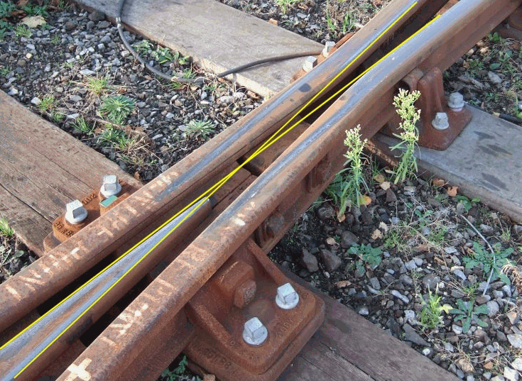 thanks to Mick Nicholson for the photo It is well worth taking a few thou off the top of the nose of model vees for the same reason (assuming coned wheels). p.s. wheel coning serves no practical purpose on a model. It is purely for appearance. cheers, Martin. |
||
|
posted: 3 Oct 2019 21:37 from: Andrew Duncan
click the date to link to this post click member name to view archived images |
Martin Wynne wrote: Andrew Barrowman wrote:Hello MartinDo full-scale railways compensate for that effect at all? Perhaps the wing rails are adjusted upwards slightly. I'm pretty sure Martin will know.Hi Andy, I'm surprised to hear that the coning serves no purpose in miniature scales? I thought it was a cunning ruse to keep the relative speed of the wheels at each end of the axle the same when negotiating a curve. Is my understanding naive in the context of model railways because of the sharpness of the curves that the wheels have to negotiate? Kind regards Andrew |
||
|
posted: 3 Oct 2019 21:40 from: Andrew Barrowman
click the date to link to this post click member name to view archived images |
Thanks Martin. That raises quite a few further questions but as they have nothing to do with Yeovil I should probably put them in a different thread. |
||
|
posted: 3 Oct 2019 22:08 from: Andrew Barrowman
click the date to link to this post click member name to view archived images |
Andrew Duncan wrote: Martin Wynne wrotHello Martin Hi Andrew, I'll jump in Yes, Martin is quite right. Coning works a bit like the differential on a car but it only works at large turning radii. It also requires a lot of friction between the wheels and the rail, a lot more than we typically see on model railways. It's just another example of how things don't scale very well between large scale ratios, and 1:76 is a large ratio. I'll go slightly heretical and suggest that it actually makes things worse (shock, horror!) As Martin points out, the vehicle's suspension will take up the change in level that coning creates through a crossing. But what if the vehicle has coned wheels but it does not have any suspension? (Like a large amount of 00 equipment.) That introduces an opportunity for "wobble" and potentially loss of electrical contact. I have an unproven theory that unsprung model vehicles would actually perform better with unconed wheels. Maybe someone has done some experiments? Cheers! Andy |
||
|
posted: 3 Oct 2019 22:10 from: Martin Wynne
click the date to link to this post click member name to view archived images |
Andrew Duncan wrote:Hello MartinHi Andrew, Even on the prototype coning works for steering on gentle high-speed curves only. If that was not so we wouldn't hear the common wheel squeal on sharp curves, and there would be no need for the flange lubricators often seen on such curves. Generally model curves are much sharper than the prototype, so likewise any coning of the wheels has no effect -- it is the wheel flanges which guide wheels round curves. On straighter track, variations in model axle alignments, variations in rail height, and tolerances on wheel diameter mean that any steering effect from model coning is effectively destroyed. It is easily demonstrated -- turn the flanges off some coned wheels, and try running trains. The rail head has a radiused top, so with or without coning, the wheel makes only a point contact with the inclined rail head until some rail wear has occurred. That is generally a slow process on models, usually resulting more from track cleaning than running trains. In practice the lack of working coning is a good thing. With no differential between the opposite wheels on a fixed axle, it means that one or other wheel is always slipping slightly instead of pure rolling. Which helps to keep wheels and rails clean. If our wheels only ever rolled, any dirt would be very quickly compacted into them to impair electrical pickup. If you have run a large layout for any length of time, you have probably noticed that pickup is better on the curves than on straight track. cheers, Martin. |
||
|
posted: 3 Oct 2019 22:21 from: Andrew Barrowman
click the date to link to this post click member name to view archived images |
More than slightly "off topic" but I seem to remember that, to reduce "hunting", the high-speed trains in Japan have almost no coning on their wheels. (Hunting is when rail vehicles oscillate slowly from side to side on straight track, like a pendulum.) |
||
|
posted: 4 Oct 2019 21:04 from: Andrew Duncan
click the date to link to this post click member name to view archived images |
Hello Martin This (coning achieves nothing other than looks) is a bit of a revelation to me but it all makes sense although, a part of me at least, wants to believe that the combination of compensated locos and coned wheels would give a superior performance over a rigid chassis. But maybe I'm unnecessarily mixing things up to bring in compensation into the arguement which in 00 and EM are more for traction (keeping all wheels on the rails) than whether it stays on the rails or not as in P4. Having said that I'm pleased that it helps keep the rails clean on curved track at least! Hello Andy All this talk of coning and hunting are making me think of the article in Scalefour News a while back which was from an old "Railway Modeller" from the sixties about a chap (with a double barrelled name?) who obviously studied the subject of rail and wheel synergy to good effect and was able to reverse his trains through crossovers at a scale 60mph! Not many of us could do that without mishap I suspect? Interestingly he used no coning and if I remember correctly no pin points and I think his locos had rigid chassis to boot... Makes me wonder if I've been fooling myself about the benefits of compensation even? But as soon as i say that I remember that I have two locos that are fully compensated and the way that they glide along the track, even my track, is a delight. Gone are the sudden upward movements that characterise all my other locos when hitting a miss aligned crossing nose or point blade. They float effortlessly over the lot. Lovely! Time for a cup of tea and some chocolate I think....and maybe a small cognac, in the appropriate Riedel glass? Andrew |
||
|
posted: 4 Oct 2019 21:14 from: Rob Manchester
click the date to link to this post click member name to view archived images |
Andrew Duncan wrote: ....and maybe a small cognac, in the appropriate Riedel glass?...or maybe a whiskey in an old Ravenglass tumbler Interesting watching the compensation debate. Wheels that are free to find their own level within a chassis have a lot more chance of helping with stability, traction and current collection. Have you tried this method - CSB Hope you are keeping OK. Rob |
||
|
posted: 4 Oct 2019 23:58 from: Andrew Duncan
click the date to link to this post click member name to view archived images |
Rob Manchester wrote: Andrew Duncan wrote:Hello Rob....and maybe a small cognac, in the appropriate Riedel glass? One fine day you’ll realise the error of your ways. Then you’ll either curse me for all the perfectly good whisky that you’ve missed, or thank me profusely for at last showing you the light....which will it be I wonder...? But moving on to something we can agree on, that being compensation, then yes absolutely and perhaps especially for electrical pickup. Have I tried CSB, no not yet but I do find it intriguing even if a touch more involved than even full compensation I suspect . The thing that concerns me most is having to weight the loco evenly. Having said something similar applies to compensation. I remember when building my GWR Hall from a modified Wills body and Comet chassis ( shame about the slide bars being far too close together) I over weighted the boiler. At some point I had to remove some of the lead and it actually ran better and pulled more afterwards, I presume that this was because I had too much weight over the front drivers and bogie. So no, not yet but will do so at some point when I’ve got all this track built and some stock converted from 00. Kind regards Andrew PS yes I’m well, thanks for asking. And you? |
||
|
posted: 5 Oct 2019 04:47 from: Andrew Barrowman
click the date to link to this post click member name to view archived images |
Rob Manchester wrote: Wheels that are free to find their own level within a chassis have a lot more chance of helping with stability, traction and current collection.Hi Rob, Thanks for posting the CSB link. All great stuff! I'm not sure suspension does anything for traction. Traction only depends on the total weight on the driven wheels and the type of metals used to make the rails and wheels. You can remove some of the axles and convert a 2-10-0 into a 2-4-0 and it doesn't alter the traction. Of course the civil engineering department would have something to say about it if you pulled a stunt like that that on a real railway Cheers! Andy |
||
|
posted: 5 Oct 2019 08:16 from: Andrew Duncan
click the date to link to this post click member name to view archived images |
Andrew Barrowman wrote: Rob Manchester wrote:Hello AndyWheels that are free to find their own level within a chassis have a lot more chance of helping with stability, traction and current collection.Hi Rob, I know nothing about physics so I fully expect to get shot down here, but if what you’re saying about a 2-10-0 converted to an 0-4-0 were the case, why does a Bulldog 4-4-0 not pull as much as Mogul 2-6-0 which is otherwise a very similar length and weight? I do understand that at full size all that weight on just 4 wheels rather than 10 would be too much for the track and infrastructure. Kind regards Andrew |
||
|
posted: 5 Oct 2019 14:01 from: Tony W
click the date to link to this post click member name to view archived images |
Martin Wynne wrote: Andrew Barrowman wrote:Do full-scale railways compensate for that effect at all? Perhaps the wing rails are adjusted upwards slightly. I'm pretty sure Martin will know.Hi Andy, Indeed, VERY gently lowering the tip of the crossing nose was one of the things that I was explaining to those doing my workshops recently. Something I have done to mine for years. Regards Tony. |
||
|
posted: 5 Oct 2019 14:12 from: Tony W
click the date to link to this post click member name to view archived images |
Martin Wynne wrote: Andrew Duncan wrote:Hello MartinHi Andrew, The prototype squeal of rail wheels on tight curves is often called flange squeal. An investigation into the causes of this revealed that although the flange was in contact with the side of the rail the noise was actually caused by one of the weight bearing wheel treads alternately gripping and slipping on the rail head, generally the lower wheel, which I take to mean the one on the inside of the curve. Regards Tony. |
||
|
posted: 5 Oct 2019 18:48 from: Andrew Barrowman
click the date to link to this post click member name to view archived images |
Andrew Duncan wroteHello AndyHi Andrew, According to Wikipedia (not always the most reliable source) the adhesive weight of a 3300 is 35t. The adhesive weight of a 4300 is 52.8t. Adhesive weight is the locomotive weight that is carried on the drivers so a 4300 is capable of starting a substantially heavier train before it loses adhesion (slips). The way friction works isn't intuitively obvious. If you try to slide a weight along a surface it takes a certain amount of force to start it sliding on the surface (and usually a bit less force to keep it sliding). The odd thing is you can do things like half or double the contact area between the weight and the surface and it doesn't make any difference to the required force. The force required to get the weight sliding really only depends on how heavy the weight is. That's why the number of driven wheels doesn't affect wheel slip. On a rigid chassis model locomotive some of the wheels may lose contact with the rail but that just means the wheels that are in contact are carrying a greater percentage of the adhesive weight. Hope that makes sense Cheers! Andy |
||
| Last edited on 5 Oct 2019 18:54 by Andrew Barrowman |
|||
|
posted: 5 Oct 2019 20:18 from: Andrew Barrowman
click the date to link to this post click member name to view archived images |
Tony W wrote: Hi Tony, I suspect it's the wheels on both sides. They probably alternately "stick-slip", a bit like a bow vibrating a violin string. http://en.wikipedia.org/wiki/Stick-slip_phenomenon The inside check rail is supposed to stop the outside wheel's flange climbing up the outside rail. Cheers! Andy |
||
|
posted: 5 Oct 2019 20:27 from: Andrew Barrowman
click the date to link to this post click member name to view archived images |
Tony W wrote: Hi Tony, For those of us who use rigid chassis and coned wheels, I wonder if we could get similar results by slightly tilting the wing rails vertically between the knuckle and the vee? I might have to do some experiments Cheers! Andy |
||
|
posted: 5 Oct 2019 22:04 from: Rob Manchester
click the date to link to this post click member name to view archived images |
Hi Andrew&Andy, Should have missed the 'traction' word out of my post, would have made things much simpler However, having been to a model railway show today and seen finescale compensated locos that rocked through crossing work and needed the odd push to keep going. Think it depends who puts them together... Just round the corner at the show I came across Tony Wright with his demo stand. I think there is some agreement that he can build locos that run like a dream. After he shouted at me for poking his buffers to find out if they were sprung we had a good chat. A word that was used in the conversation several times was 'pragmatic'....not a sprung hornblock or compensation beam in sight. I even have an invite to visit Little Bytham So from what you ( Andy in the US ) are saying the argument applies to weight carried on the driven wheels. Weight on non-driven pony or bogie wheels may keep the axle load down but is wasted in helping to pull the train. At least I can keep my 4x4 smug in the knowledge I can cope with the worst of the British weather Rob P.S. Yes, fairly well thanks Andrew. |
||
|
posted: 5 Oct 2019 22:37 from: Andrew Barrowman
click the date to link to this post click member name to view archived images |
Rob Manchester wrote: Hi Andrew&Andy,H Rob, I agree. How well it's all put together is the dominant factor. Lucky you didn't ask Tony if it was DCC. You'd probably have got more than a shouting Cheers! Andy |
||
|
posted: 6 Oct 2019 00:20 from: Rob Manchester
click the date to link to this post click member name to view archived images |
Thanks Andrew, Maybe I should have suggested DCC sound, flickering firebox LED's and a steam generator ? He sticks with Markits/Romford crankpins to go with the metal centered wheels that he prefers. I need the finer profile Gibson wheels for my EM-SF standards but still prefer his choice of crankpin. Rob |
||
|
posted: 6 Oct 2019 01:26 from: Nigel Brown click the date to link to this post click member name to view archived images |
Andrew Barrowman wrote: Andrew Duncan wroteHello AndyHi Andrew, I'm a bit suspicious about this for a number of reasons. Things like why were Singles discontinued; how does the radius of a wheel affect the coefficient of friction; and so on. Nigel |
||
|
posted: 6 Oct 2019 06:38 from: Andrew Barrowman
click the date to link to this post click member name to view archived images |
Nigel Brown wrote: I'm a bit suspicious about this for a number of reasons. Things like why were Singles discontinued; how does the radius of a wheel affect the coefficient of friction; and so on.Hi Nigel, I'm pretty sure the mechanical engineers preferred to have as few driven wheels as possible. I believe the singles were discontinued because the civil engineering departments set axle load limits to reduce permanent way maintenance as it became necessary to build ever larger locomotives to haul ever heavier trains. The coefficient of friction has nothing to do with a wheel's radius. It only depends on the materials that the wheels and rails are made of. For dry steel on steel the static value is between 0.5 and 0.8 (according to this.) http://www.engineeringtoolbox.com/friction-coefficients-d_778.html Cheers! Andy |
||
|
posted: 6 Oct 2019 18:37 from: Andrew Duncan
click the date to link to this post click member name to view archived images |
Rob Manchester wrote: Hi Andrew&Andy, Hello Rob I’m not acquainted with Tony wright, but anyone who can build a chassis that runs like silk can’t be all bad and your quite right about it the way that it’s put together that counts more than anything, compensated or not. Andy, I follow your logic on the weight question but as to wheel diameter making a difference I’ve understood that the larger the diameter the better the grip because of the rail deforming under the weight of loco giving a greater area of metal to metal , hence greater grip. Or am I mixing my physics, traction verses friction, otherwise Robs 4x4 wouldn’t be any advantage over a two wheel drive car would it? Yours confused of Reigate.... |
||
|
posted: 6 Oct 2019 18:59 from: Rob Manchester
click the date to link to this post click member name to view archived images |
Hello Andrew, I never was very good at Physics at school ( I liked woodwork and watching the clock for hometime ) but managed to survive a whole working life without feeling left out. In the early 1970's the UK police forces decided they wanted a vehicle to move broken down trucks around the expanding motorway network that was also fast enough for patrol use. Did they choose a 3.4 or 5.3 Jaguar - No. Did they choose a 3 litre Ford Consul - no. They looked at the newly developed Range Rover which they tested before buying a fleet of them. A comination of the grip provided by the rubber to asphalt/tarmac/concrete friction and the provision of a low ratio gearbox to generate sufficient power at starting speeds got the job done. And no, my 4x4 isn't one of those gas guzzling things.. Reading railway books one often comes across a statement such as ' this class of engine was ideally suited to the lines it worked'. I understand there are many variables across the classes of loco but surely driving wheel size must have some effect apart from just setting a theoretical top speed. The GWR 54/64/74xx locos are a case in point. Earlier versions had 4'7" wheels but later they changed to 5'2". Rob |
||
|
posted: 6 Oct 2019 19:48 from: Andrew Barrowman
click the date to link to this post click member name to view archived images |
Andrew Duncan wrote:Hi Andrew, You're making it harder than it is The only thing you need to remember is that the amount of friction (stickiness if you like) is independent of the contact area. It only depends on two things; the coefficient of friction for the two surfaces and the force pushing then together - in this case the force is produced by the weight carried by the wheels. As I said, you can double or half the contact area and it doesn't make any difference to the amount of friction. That's the bit people have a hard time getting their heads around. So no, greater area of metal to metal doesn't make any difference. If you want more friction you either have to increase the force (add weight, magnets) or increase the coefficient of friction (rubber tires, sand). More wheels won't help. Rob's 4 x 4 has better traction in adverse conditions because all of the vehicle's weight is carried on driven wheels so the adhesive force is close to double what it would be if only two of the wheels were driven. Cheers! Andy |
||
| Last edited on 6 Oct 2019 19:48 by Andrew Barrowman |
|||
|
posted: 6 Oct 2019 20:06 from: Rob Manchester
click the date to link to this post click member name to view archived images |
Andrew Barrowman wrote: Andrew Duncan wrote: Andy, Better traction even with 1 or 2 wheels off the ground as most of the power is then being fed to the other wheels that are carrying all the weight. So are you saying that the width/diameter of vehicle rubber tyres doesn't effect the amount of friction and hence grip or is the 'rubber' a key word here. Rob |
||
|
posted: 6 Oct 2019 20:16 from: Nigel Brown click the date to link to this post click member name to view archived images |
Andy, I'm sure you're right on the raw theoretical side, and it corresponds with my memories of the issues in the past. Nevertheless, I have a feeling that the real-world issues are more complex. Why do racing cars have such big tyres, if the only thing which matters is the weight on the driving wheels (assuming the rubber is the same)? Why do racing cars use wet and dry tyres? Can see that the wet tyres are designed to channel water away from under the tyre, but in the dry why would dry tyres be better? Cheers Nigel |
||
|
posted: 6 Oct 2019 20:25 from: Andrew Barrowman
click the date to link to this post click member name to view archived images |
Rob Manchester wrote: Hello Andrew,Hi Rob, I liked woodwork and metalwork too. My chemistry teacher was horrible and put me off chemistry for life but my physics teacher was really great and got me going in the right direction (eventually). Yes, four-wheel drive almost doubles (depending on the weight distribution) traction compared to two-wheel drive because it greatly increases the adhesive force. Pretty much essential around here in the Winter too. I have a 4 x 4 1500 RAM truck (smallish diesel engine) and my wife has a Jeep Wrangler although for many years we drove two-wheel drive cars and improved the coefficient of friction in snow and ice with studded tyres. They are not really necessary with four-wheel or full-time all-wheel drive. Changing the wheel diameters on locomotives is just like changing gears in a car. Smaller wheels lower the top speed but assuming everything else is unchanged, smaller wheels increase the torque which, assuming the wheels don't slip, increases the pulling force. That's useful for hauling longer goods trains or reducing stalling on routes with a lot of steep gradients. Cheers! Andy |
||
|
posted: 6 Oct 2019 20:53 from: Andrew Barrowman
click the date to link to this post click member name to view archived images |
Rob Manchester wrote: Andy, Yes, rubber tires on asphalt or gravel are a lot different from steel wheels on steel rails. And then there are all the variables associated with rubber composition, water, ice, temperature, type pressure, extreme lateral forces (cornering at high speed) surface roughness, wear rates, tread pattern, etc etc. And then there's the question of static versus kinetic friction. All of these things affect the coefficient of friction and anything that affects the coefficient of friction can make a big difference. But for one type of rubber on dry asphalt being forced in a straight line the friction and hence the maximum traction does not depend on contact area. Depending on surface conditions it can actually go the other way. In snow it's best to run with narrow tyres rather than wide tyres. Wider tyres are more inclined to "float" on top of the snow. (Don't ask me how I know |
||
|
posted: 6 Oct 2019 21:14 from: Andrew Barrowman
click the date to link to this post click member name to view archived images |
Nigel Brown wrote: Andy,Hi Nigel, Exactly the same physics applies, the problem is the type of tyres and road conditions have a huge influence on the coefficient of friction. Other than dropping sand, locomotives can't do much to influence that. Fat tyres on racing cars are there for (at least) two reasons. Heat dissipation and wear rate. Narrow sticky tyres could provide just as much traction but they would disintegrate in no time at all. Even the fat ones only survive for a very limited distance. And the surface temperature of narrow tyres would increase dramatically and that would alter the coefficient of friction too. Racing cars don't usually have much of a problem obtaining enough friction to travel in a straight line (other than dragsters). The tyres are being selected more to ensure the cars corner at the highest possible speeds. If they added flanges they wouldn't have to worry about that. Cheers! Andy |
||
|
posted: 6 Oct 2019 22:21 from: Andrew Duncan
click the date to link to this post click member name to view archived images |
Andrew Barrowman wrote: Andrew Duncan wrote:Ok Andy I think I’m beginning to understand, thank you. I can relate now to the weight of the whole vehicles weight coming to bear on the driven wheels of a 4 wheel drive. This is as opposed to two wheel drive only having approximately half the vehicle’s weight (or less in the case of rear wheel drive ) providing a downward force for traction.Hi Andrew, Thank you very much because as I write this, greater clarity Is dawning! Enlightened of Reigate.... Kind regards Andrew |
||
| Last edited on 6 Oct 2019 22:35 by Andrew Duncan |
|||
|
posted: 7 Oct 2019 03:28 from: Matt M.
click the date to link to this post click member name to view archived images |
Hi everyone, Am enjoying this diversion from the main topic of the thread. (Enjoy the thread as well). Single driver locos were discontinued because they could not put down enough tractive effort as trains got longer and heavier. Locos with coupled drivers spread the tractive weight across multiple axles. When one wheel starts to slip it is held in check by the other coupled wheels. The formula for tractive effort is: Tractive force in lbs. = Diameter of cylinders in inches x Stroke of pistons in inches x Mean effective pressure on pistons in lbs. per square inch - over: Diameter of driving wheels in inches. (Just the one driving wheel, not combined). If you have a 4 cylinder loco you double the equation. Compounds are a little trickier but similar to work out. Having your tractive effort you need to allow for your conditions of service, like goods or express and type of track it will operate on for example gradients and curvature. This is where position of weight comes in. You need to look at train resistance as well. This includes issues of wind resistance; number of journals, the average condition of these journals, the weight upon these journals and the friction that you have to overcome to start a train; the velocity you expect the train to reach during operation and state of the Permanent Way. Once you have these you are working out the effects of gravity on the train. Hills and curves. Then it is time to work out the weight distribution. Centre of gravity is the main issue to work out. Rotational and longitudinal. Two weights are important, sprung weight and total weight. The height of the centre of gravity on English steam locos was generally designed at around 5 to 6 foot. Rotational is how far can you tip the loco before; 1) you lose tractive efficiency on the lightened side of the loco; 2) you lose contact with the rail allowing the possibility of derailment and 3) the damn thing tips over. Longitudinal is calculated and adjusted to reach the maximum allowed weight per axle over the drivers. These must be of equal measure. The adjustments are either to shift weight in the structure of the loco; change the distance between the axles; or effectively cheat by using equalising beams and such. This is the important part of maximising the tractive effort that the loco can apply. That is, it can work through its expected performance range without slipping. As a rule of thumb the difference between the position of the total weight and sprung weight longitudinal centre of gravity can only be 6 inches. Tank locos are more painful to work out due to the constantly changing weight in operation. And we haven't even touched upon the issues with reciprocating masses and their effects. Nor what the trailing mass of the train does. Physics of movement are also an issue. At speed your centre of gravity moves forward as Mr Barrowman would be well aware of. Cars are a slightly different animal. Yes centre of gravity is still important, so distribution of weight is critical for certain performance requirements. That is why front mid-engined and rear mid-engined cars tend to dominate the cutting edge of sports car racing and high performance cars. In the old days it was transaxle gearboxes to get the beat weight distribution. Outside of Rally cars four wheel drive not so much. Though efficient there are weight and mechanical friction penalties. With four wheel drive It is not an issue of weight so much as options. You have more mechanical options. When one wheel loses grip three more are still working and when one axle set loses grip the other one can bail you out of trouble depending on how complex the differential/stability control system is. With four wheel drive off-road it also comes down to axle articulation in the really rough stuff. In fact suspension design is as important as good tyres as it helps keep the maximum amount of tyre patch in contact with the road surface. Your contact with the road in an average car is effectively four rubber patches not much bigger that the heel of your shoe. When you hit the brakes you are only slowing the rotation of the wheels. The effort of slowing the mass of your car at speed is two blokes dragging their heels 'Flintstone's' style. Regards, Matt M. |
||
|
posted: 7 Oct 2019 18:19 from: Nigel Brown click the date to link to this post click member name to view archived images |
Thanks for that excellent description, Matt. Very informative. In making model locomotives I've found weight distribution is critical. I've managed to improve this in a number of instances by using compensation beams. For example, I built a Metro 2-4-0T, where I incorporated a flexible chassis by having the leading drivers (which had the drive) fixed, the rear driving axle pivoted at the centre, the leading axle treated as a pony truck, and weighted so the CoG was behind the leading drivers. So the drivers carried all the weight, but unequally. It worked but I wasn't really happy. I built a second chassis with twin compensation beams between the drivers, and the leading axle pivoted so that the loco was fully compensed, and weighted to have the same amount an all wheels. Much better. Ran more smoothly and pulled a lot more without slipping. In 4-coupled engines I now use twin beams as a matter of course. It turns 4-4-0 and 0-4-4 engines from being a pain to get right to being dead easy. Nigel |
||
|
posted: 7 Oct 2019 21:02 from: Andrew Duncan
click the date to link to this post click member name to view archived images |
Hello Matt That is an answer and a half. Thank you... I think, although still trying to take it all in and indeed I'm not sure I've got the right brain to do so, but admire those who have. Not withstanding all the physics, like Nigel I shall continue to build fully compensated loco chassis because they run so smoothly that even compensation with one fixed axle doesnt really compare. Thanks again. Kind regards Andrew |
||
|
posted: 8 Oct 2019 07:09 from: Andrew Barrowman
click the date to link to this post click member name to view archived images |
Andrew Duncan wrote: Hello MattHi Andrew, Fortunately most of what applies to full scale locomotive design does not have too much to do with locomotive design at the scales we are working in. A fully compensated chassis will give you as much traction as you can get from the weight carried on its drivers and it's likely to have better contact with the rails too, so go for it. As I'm lazy I'm always looking for shortcuts. My current "project" is to I'll post a link if I can get it to work. Cheers! Andy |
||
|
posted: 9 Oct 2019 05:06 from: Matt M.
click the date to link to this post click member name to view archived images |
Hi Andy, Andrew, Rob and Nigel, I agree. Full size locomotive design parameters don't scale down. And I also agree that compensation and springing is useful to have on a model. Weight over the driven wheels is important regardless of whether it is a rigid or compensated. I would also add the use of side control springing on leading and trailing bogies, pony trucks and radial trucks to allow them to perform one of their main roles (as on the prototype) more reliably. And decent electrical pick-up. I just like to understand the reasons that the prototypes looks and behaves the way they do. Then you can make decisions about the level of compromises you have to or are willing to make for the model to work on out way to small curves. That was the simple version Andrew. And yes, the maths makes my brain hurt. Especially as my early schooling corresponds to the change from imperial measurement to metric in this country. It would take a couple of months dedicated run up for me to be confident or vaguely proficient at the require maths. But understanding the theory is all you need unless you are designing the real thing from scratch. I didn't have enough time in the last two days to go over wheel size choices. But as I have an hour I thought I should reply and add to my original missive. Yes, wheel size is linked to overall speed of the loco, but more so to the efficiency of the cylinder to transmit power for drawbar pull. Not a problem for electrically powered models but an issue for the live steam people as steam physics doesn't scale down. The simple (and I do mean simple as there are many variables) rules of thumb version for driving wheels is this: 1) The rotational maximum is assumed to be 360 rpm. (A. This is related to number 3 in this list. B. It is slightly lower, in the 330's I think. C. There were European locomotives that were running at 400 plus by the 1940's) 2) Peak cylinder piston efficiency is assumed to be roughly half of that at 180 rpm. The lbs. per square inch on the piston face become lower the faster that the cylinder moves above that rpm. There are thermal efficiencies to running a faster piston but we move from the simple to the complicated explanation. (Also to note that better metallurgy, packing/seals, superheating and better porting and valve design have an affect on this.) 3) 1 inch of wheel diameter is roughly equal to 1 mile an hour top speed. (Not a deciding factor but none the less something a designer has to keep in mind). Given this information you can see that a large single driven wheel can be very efficient for high cruising speed with maximum drawbar pull, low fuel and water expenditure and low friction on the motion. But equally not so happy when dealing with the initial requirements of overcoming the inertia of a stationary train. Indeed all the accounts that I have read suggest that multiple occurrences of wheel slip when starting to move a stationary train was part and parcel of using single driving wheel locos. Steam sanding prolonged the working life of the single type of loco, but then the wheel spin is creating flat spots on the rail which would not have amused the Permanent Way staff. To be fair the same problems apply to any locomotive with large driving wheels whether coupled or not. Large wheels give you lower friction issues through the full action of the running gear so from a locomotive engineer's point of view this gives a feeling of being freer running. They bridge gaps at points and crossings better and help the overall smoothness of the ride. But they also transmit into the axles at a much higher rate the shock side thrust created when transversing points and crossings. Also larger diameter wheels don't cope well obstruction on the rail and are thus prone to derail at a higher rate in such cases than smaller diameter wheels. Larger wheels also limit the size of the boiler for width and due to the extra hight of the axle the how low you can set the boiler in the frames, thus affecting the hight of the centre of gravity. Though higher centre of gravity gives you smoother running with savings on wear and tear on tyres and Permanent Way. With GWR Pannier locos mention by Rob the variation would be an issue of maximising efficiency for the reasons described above. I haven't dug out my references on those locos but I thought that the earlier 54's had the larger wheels. The 64's had the smaller wheels as they were being used on the steeper Welsh lines. 74's were the same but higher boiler pressure. Can't remember if there was a difference with the cylinder measurements as well. Suburban commuter locos are set up for efficient, smooth and rapid acceleration from stop to stop. Shunting locos are the same. Mineral and goods locos are designed around maximum tractive effort at lower speeds. The Panniers were a decent slow speed all-rounder. For those who are interested the adhesion weight for a loco to dry rails is 600 lbs. per ton. Wet rails is 550 lbs. per ton. Most English locomotives were designed around 450 lbs. per ton to allow for the rapid drop in adhesion from grease, frost and snow. Andy is correct in that size of wheel makes no difference to adhesion in the static weight distribution. Nor does it make any difference to the friction co-effieciant. On the matter of bogies, pony and radial trucks they do contribute to the adhesive and traction weight management of the loco. On a 30½ chain curve at 50 miles an hour 20% of the static weight on the inside wheels of an average 4-6-0 goes to the outside wheels. And the flange force on the outer leading bogie or pony truck wheel is measured in tons per square inch. Other than shortening the overall length of rigid frame thus allowing bigger locos to go around smaller curves the main job of the bogie and trucks is to facilitate faster and safer entry and exit of curves. Good design of these units can contribute greatly to a smoother ride as well. To finish on a more Templot like note. When designing pony trucks the lateral springing or swing link system has to be designed so that when going over a 1 in 7½ and 1 in 8 obtuse angle diamond crossing (where it is impossible to provided a check rail of the normal type) that the lateral springing doesn't let the outer wheel shift to the wrong side of the vee. There is over 4 inches of travel where this is possible. Control of this problem is usually done by a series of ridges on the friction plate but has to be carefully worked out to keep the forces involved reasonable. As Andy correctly points out most of this does not apply to your models. But it can help with understanding why the prototype looks and behaves the way it does. Hope people find this information interesting or helpful. Regards, Matt M. |
||
|
posted: 9 Oct 2019 22:07 from: Andrew Duncan
click the date to link to this post click member name to view archived images |
G Andrew Barrowman wrote: Andrew Duncan wroteHello AndyHi Andrew, I’m sure a man who can print his own track wont have any problems putting tires on a tender drive and pickups on the loco and have it pulling the side out of a house in no time at all! Look forward to seeing my first 0-4-0 pacific 😀 Andrew |
||
|
posted: 9 Oct 2019 22:34 from: Andrew Duncan
click the date to link to this post click member name to view archived images |
Hello Matt You obviously know a thing or two about these things and certainly great deal more than I do, which isn’t perhaps saying a lot! I’m glad we’re in agreement that compensation is beneficial in models both for road holding and electrical pick up. When it comes to pony truck and bogie side control I may have to revisit this. On my old layout which was built in 00 I had some very sharp curves and found on the odd occasion when I tried to include side control it somehow contrived to derail the loco. I can’t remember now what the reason was, but at the time I gave up trying to get the loco to be lead into the curve and let all hang loose so to speak! With far gentler radii on Yeovil Mk2 perhaps I can try again Anyway thanks again for your mini treatise on the subject, highly informative. Kind regards Andrew |
||
|
posted: 9 Oct 2019 23:33 from: Rob Manchester
click the date to link to this post click member name to view archived images |
Hello Matt, Many thanks for the long post(s) - a lot to think about in them even if some of it doesn't need to be acted on when building our models. You may be right about the 54/64/74 Panniers, I remembered the different wheel sizes from a previous build of a kit that was supposed to cover all three classes. When I tried a set of the larger wheels they wouldn't clear the splashers supplied Any idea why the Southern Railway's Bullied 4-6-2 designs were so prone to slipping from a standing start ? They seemed to be much more trouble than the LMS,LNER and GWR pacifics - and that is before you consider the valve gear and other known weak points. Handsome locos in rebuilt form though... Thanks again Rob |
||
|
posted: 10 Oct 2019 07:52 from: Matt M.
click the date to link to this post click member name to view archived images |
Hi Andrew and Rob, I'm glad you find the information interesting. Just a little background. I'm not an engineer, though I can read in it reasonably happily. (Musician. Classical pianist by training). My knowledge base has been growing over the last 8 years as a result of the slow on and off renaissance of 7mm modelling of the New South Wales Government Railways. New South Wales is the only state in Australia that models O gauge to those standards. The rest use 1/48th. My preferred standards were S7. I had the good luck to meet and become friends with a gentleman who wanted to design kits of NSWGR locomotives to the quality of Finney, Mitchell and Modern Outline. From him I have learnt about the compromises one makes when designing a scale model to perform as the prototype but with the issues of oversized flanges, tiny clearances, sometimes due to materials that are thicker than scale and seriously under sized radius curves. The other thing he hammered home was the need to understand what you are modelling. His first kit of a Z12 class was delivered but we could not get enough subscribers for the second kit to make it viable. I had started to do the research for 7 locomotives plus Clyde Locomotive Depot in Sydney c1910 as a layout that three of us were going to build. 36 feet of Templot printout in two sheets. Unfortunately the third member was diagnosed with a brain tumour and passed away after 18 months. My friend had some contra medication issues that began to affect his memory plus a scare with cancer. This meant he shut down his engineering consultation business and, due to the lack of interest, the kit design business. With my being a carer for the second time of an elderly ill parent the modelling has stopped for the several years but the research continues. Currently I field question from and for the Australian Railway Historical Society (NSW) Resource Centre when they need something and provide them with sets of copied and collated information. I have also done the same for the New South Wales Government State Archives and Records. I help our remaining 7mm kit manufacturer with research, with the results of some of that being used by DJH on the last two locomotive kits they have done for him. I have helped by providing information and sources for some of the research of a recently released book "New South Wales Railways in Colour 1855 - 1957" by Garry Saunders (which is a fabulous book), and I did some initial checking editing for his manuscript (with the elderly parent). Also put him in contact with another friend I supply information to Greg Edwards who did the colour profiles used. Greg runs a business called Datasheets that supplies scale drawings for modellers. Garry has become a good friend as well. Due to my research I was introduced to the gentleman co-ordinating the rebuild of 3801 (it is for NSWGR fans what the A1 'Flying Scotsman' for English railway fans). We have become good friends and I have sourced and supplied high quality reproduction drawings to help with the restoration. I am currently involved in the grunt research and collation of information of what we hope will be the second volume of the "Goods Wagons of the NSW Railways". The first volume, which goes from 1855 to 1905 had a slightly tortured development so we are hoping to get this one done faster. When it comes to modelling though most of the people on this forum would have much more practical experience than me. If I dare to comment it would be from a limited personal practical experience, from advice and knowledge shared by long time modellers who have output I respect, copious reading (most of which comes from the usual English sources) and a decent amount of reading and some practical work (mostly with cars) in mechanical engineering and miniature mechanical engineering. Without looking at the set-up of your previous experiments in 00 Andrew I can only guess. It could be that given a limit of travel by the side spring the pony truck or bogie may have found the spring a useful fulcrum to lift an outside wheel enough to climb the rail. The real thing has problems with that as well. The NSWGR had three 2-8-0 goods loco classes that were developed from the first class. When they were rebuilt with the same firebox, boiler and smokebox they were referred to as the Standard Goods' locos. The last of those classes the D55's had Southern Valve Gear. And a rather nasty habit of lifting the inside pony truck wheel on a climbing tight curve. They were banned from certain lines due to this. The few times I've seen side springing done on a model loco it does appear to give it a better look going into curves and formations. Whether it is with the trouble I really don't know. It was one of things I wanted to explore but ran out of spare funds and, I admit, time. That and all wheel pick up using carbon bushes from Marlkin Z scale loco motors. (Not my idea but from a member of the S7 group. I think it was the Z scale ones). Rob one of the fun facts imparted to me by a long time observer and chronicler of modelling the NSWGR was when manufactures in HO want to do a model of the D55's they often made the mistake of getting the wheels sorted first. Off the drawings. Woo Hoo! But those don't fit under a scale frame and footplate measurements. As far as the Southern Railway's Bullied 4-6-2 designs go I would assume it is an issue of maximum static weight restrictions meeting the drawbar pull requirements and have a slightly less than ideal match between piston maximum output and wheel size. As I mentioned all large driving wheels can have the problem. Thank you for your kind words and appreciation of my longer technical missives. Matt M. |
||
|
posted: 10 Oct 2019 14:27 from: JFS
click the date to link to this post click member name to view archived images |
Rob Manchester wrote: Any idea why the Southern Railway's Bullied 4-6-2 designs were so prone to slipping from a standing startI think there were three basic reasons. Firstly, from an early date, there was no sand on the leading drivers because Bullied did not want it on the slide bars. Secondly, leaking oil from the oil bath (and there was a lot of it!) tended to get thrown outwards by centrifugal force onto the backs of the tyres - not a problem at speed, but once the loco was standing the inevitable becomes inevitable. Thirdly, the valve gear: the 3:8 rockers and the angularity of the rockers at full valve travel meant that at any speed, the valves were prone to excessive and irregualr over-travel - so when a slip occurred, the tractive effort tended to increase - even if the gear was notched-up. There were some other factors which did not help - like having the regulator valve in the dome meaning that there was a superheater full of steam to use up before a slip cound be controlled. The LMS and LNER pacifics also suffered from this whereas the GW used somebox regulators giving much better control. I know that Bullied's wacky designs have their fanatical admirers, but I don't know of any with a Professional Engineering qualification - it was the same when Bullied retired: he was so proud of a card signed by all the driver's at Exmouth Junction that he failed to notice that it was not signed by a single fireman nor fitter! And his legacy lives on:- http://www.youtube.com/watch?v=4rAwlboiOHY (thank goodness he had no hand in the Class 47s or that train would be there yet!) But I think there is something else which is more relevant to us as modellers. Pacifics in Continental Europe were MUCH more sure-footed than their UK equivalents. I visited both West and East Germany many times in the seventies and travelled for miles behind Pacifics and slips were very rare indeed - even though loads were heavy and starts often quite smart. I think the reason for this is down to the fact that they all had Equalisation between the springs on all axles (ie in model-speak, they were compensated). The same was true everywhere else as far as I know, and I never understood why UK pacifics were not so equipped - it might also have massively reduced the incidence of broken springs! Good thread! Keep up the good work all! Howard Edit:- by way of illustration:- http://www.youtube.com/watch?v=00aeA-sfRqU or this - a 3-cylinder pacific in Lower Saxony's best weather... http://www.youtube.com/watch?v=-IWW_5VK8Mw |
||
| Last edited on 10 Oct 2019 15:14 by JFS |
|||
|
posted: 10 Oct 2019 16:37 from: Matt M.
click the date to link to this post click member name to view archived images |
Hi Howard, Thanks for the information. Without specific information about particular locos it becomes a bit of a guess as to their foibles. Oil on the treads would drop the adhesion weight to 300 lbs per ton. And you have explained why the regulators moved from below the dome to being part of the steam header in NSWGR practice with the late locomotives. With beams between springs in NSWGR speak they are compensated as well. And yes that was the practice on later engines and retrofitted on some surviving earlier classes as well. With the roller coaster nature of some of the main lines fractured frames were more of an issue here and the late locomotives had cast steel frames to try to lessen the problems. I also note a resistance to roller bearings in the various publications I have on locomotive design from England. The Americans loved them and the NSWGR used them on their last designs in the 1940's. Another difference Continental Europe /American locomotive design had with England was the use of large diameter cylinders with shorter throw. I avoided valve gear design issues associated with wheel slip as I find no way of discussing that without complication. It varies so much over time and builder/designer preferences. You do have to know the set up in a particular locomotive class. My friend dealing with 3801 spent 40 minutes explaining how the 'trick' piston valves fitted to some of the 38 class worked. I got it then but I'm damned if I could explain it now. I enjoy Templot forum threads as I have picked up a lot of practical modelling information, track design and history information Regards, Matt M. |
||
|
posted: 10 Oct 2019 19:09 from: Andrew Barrowman
click the date to link to this post click member name to view archived images |
Hi Andrew, There will be no rubber tires (or tyres) 2983_101359_180000000.jpg 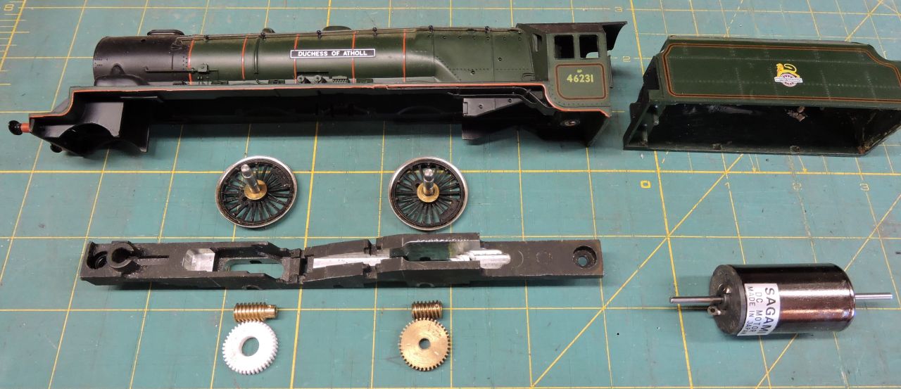 It will be "tender powered" by that rather large Sagami motor in the tender driving the first and third driven axles via 20:1 reduction gears. The entire locomotive body will be stuffed full of lead (depleated uranium being unobtainable). The worm and worm-gears will be Tri-ang replicas made by yours truly. They are "two-start" gears which help to reduce friction. Center driver and coupling rods will be pretty much along for the ride. Cheers! Andy |
||
|
posted: 10 Oct 2019 19:25 from: Andrew Barrowman
click the date to link to this post click member name to view archived images |
JFS wrote: Rob Manchester wrote:Hi Howard,Any idea why the Southern Railway's Bullied 4-6-2 designs were so prone to slipping from a standing startI think there were three basic reasons. Firstly, from an early date, there was no sand on the leading drivers because Bullied did not want it on the slide bars. Secondly, leaking oil from the oil bath (and there was a lot of it!) tended to get thrown outwards by centrifugal force onto the backs of the tyres - not a problem at speed, but once the loco was standing the inevitable becomes inevitable. Thirdly, the valve gear: the 3:8 rockers and the angularity of the rockers at full valve travel meant that at any speed, the valves were prone to excessive and irregualr over-travel - so when a slip occurred, the tractive effort tended to increase - even if the gear was notched-up. I believe 4-6-0's are a lot more "sure footed" than Pacifics. If that's true there might be a simple explanation. When a 4-6-0 tries to start a train the pull on the drawbar tends to lift the front of the locomotive. Obviously it doesn't lift it very far but that does transfer some axle load from the front drivers to the rear drivers. (It might unload the springs in the front bogie to some extent too.) That has no negative effect on the locomotive's adhesive weight. It just means the rear drivers are seeing a greater share of it. With a Pacific the drawbar pull also transfers weight to the rear of the locomotive but that does reduce the adhesive weight because some of it is transferred to the pony truck. Cheers! Andy |
||
|
posted: 10 Oct 2019 19:57 from: Rob Manchester
click the date to link to this post click member name to view archived images |
Thanks Matt and thanks Howard. All useful information. Back on track with Andrews track maybe Rob |
||
|
posted: 10 Oct 2019 23:32 from: Andrew Duncan
click the date to link to this post click member name to view archived images |
Matt M. wrote: Hi Andrew and Rob,Hello Matt Thanks for your further thoughts on side control. Ive a feeling you’re correct in your thought that it was the wheel climbing up the side of the rail that put me off, and at the time for whatever reason I experimented no further. When I’m a bit further on with the track side of things I’ll then enjoy experimenting with things like this. As you’ve already implied, watching say a 4-4-0 being steered into a curve is a very different experience to one that has its buffer beam half way across the track only to be violently brought into line a few moments later. The effect is even more pronounced on an 0-4-4 tank like a LSWR M7 in reverse! I had an old Triang one as a boy and even then thought it looked ridiculous going backwards round admittedly very tight curves! Your ideas on pickups sound a bit different ? What advantage does a carbon brush have over brass or phosphor bronze? Getting late, time for bed! Kind regards Andrew |
||
|
posted: 11 Oct 2019 01:08 from: Nigel Brown click the date to link to this post click member name to view archived images |
Andrew Barrowman wrote: Hi Howard, There was the well documented case of the GWR / LNER exchange trials pitting Castles against the A1 pacifics, around 1925. One morning, the LNER upper echelons gathered at King's Cross to watch a Castle attempt to haul an express out of the station and up the bank, a notorious task which even Gresley's pacific had big trouble with. Cue much joking as to the eventual outcome amongst watchers. Then silence as Collett's masterpiece glided out of the station and disappeared up the bank with scarcely a hitch! Re 4-4-0s, here's a snap of a Dukedog 4-4-0 chassis I built: 528_102003_380000000.jpg 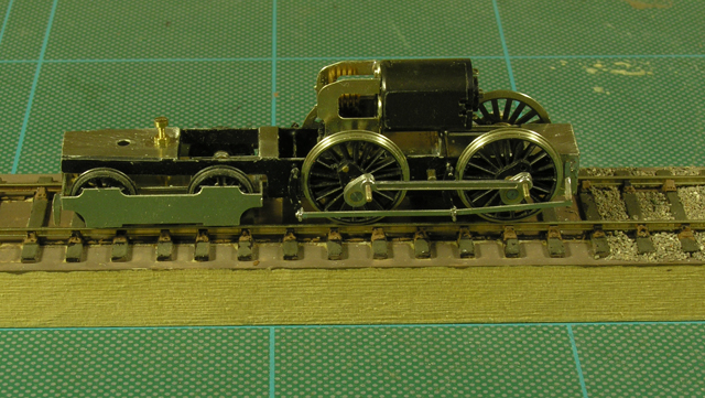 It has twin compensation beams on the drivers, and for the bogie a single centre bolt which passes through a slot in the bogie; a nut on the bolt controls the height of the chasses front. Although the bolt can slide in the slot, the friction between nut and bogie helps guide the front around curves. Nigel |
||
|
posted: 11 Oct 2019 03:15 from: Matt M.
click the date to link to this post click member name to view archived images |
Hi Howard, The silver carbon pick-up is the idea of Dave Nicholson from the S7 group. Dave migrated from P4 to S7. He found that he wasn't getting the quality of running he wanted with phosphor bronze wipers and DCC. After some tests proved to him that the weak point was the wipers he looked at the alternatives and with advice from other S7 modellers went to Slater's Plasticard plunger pick-ups. These worked well for a while but in a short amount of time the wheels developed a groove on the back where the plunger was contacting. This had an audible sound as well. After two years the sound stopped but that was because the groove had widened out so far and the plunger had started acting as a brake. One for each driving wheel. After some thought Dave came up with a solution that involved modifying the Slater's pick-up with a silver carbon bush from Bachman's N scale motors fitted to the end. The article in the S7 Newsletter No.82 of November 2010 takes you through the steps to do this. Dave had stopped using modified Slater's units and was making his own. He could make a set of six in an evening. There was to be a second article to describe the development of the smaller version that he developed for bogies and pony trucks (and subsequently used for pick-ups on wagons and carriages) but that was never published unfortunately. Advantages: 1. Exceptionally low friction. So much so that all wheel pick-up for small locos hauling a train were the rolling stock are also using these for lighting and remote coupling is not an issue. 2. Long life. Dave has only had to replace the plunger springs every 4 years as they lose temper. But in the ten years up to the article being written he had not replaced any plungers but you do need to lap the back of the wheel for that result. 3. Pretty much self cleaning. If you are interested I could ask if the article could be made available in someway. Regards, Matt M. |
||
|
posted: 11 Oct 2019 09:50 from: JFS
click the date to link to this post click member name to view archived images |
Andrew Barrowman wrote: I believe 4-6-0's are a lot more "sure footed" than Pacifics. If that's true there might be a simple explanation. Indeed so, and my point is that the effect is almost entirely eliminated when the axles of a Pacific are equalised. The problem is that the adhesion of three coupled axles is limited not by the total adhesive weight, but by the weight on the lightest driven axle - when that loses grip, its tractive effort is transferred by the rods to the other two so the whole lot slips. You can think of it as if the effective adhesive weight of three coupled axles is three times the load on the lightest axles. To avoid the unloading effect, the Continentals used equalisation between the rear carrying axle and trailing coupled axle as well as the driving axles. I think it was Churchward who did away with equalisation when he realised his 4-6-0s did not need it, unfortunately, those who came later did not question it for Pacifics hence their adhesion was as poor as it was. For me there are always important lessions from the real thing - if we have a slippery loco, check for a "light" axle before simply adding more weight. Equal loading is easier with (correctly designed!!!) compensation than with springing, but don't take it for granted. We don't all have to get 14 coahes up a 1:70 gradient, but I know a few good modellers who have been embarrassed when they have taken their prize loco to "guest" on a large layout. In fact, I might be one of them... What news the track Andrew? |
||
|
posted: 11 Oct 2019 12:09 from: Matt M.
click the date to link to this post click member name to view archived images |
Not that I mind saying hi to Howard, (Hi Howard), but of course my last post was for Andrew. That is what you get for 3 hours sleep. I'm going to follow Mr Duncan's wise example and go to bed. Cheers all, Matt M. |
||
|
posted: 12 Oct 2019 00:58 from: Andrew Duncan
click the date to link to this post click member name to view archived images |
Andrew Barrowman wrote: Hi Andrew,Woops well spotted Andy. Tyres it is! Or rather no rubber tyres. When you referred to a tender drive I’m afraid I thought you were going for an entirely pragmatic approach. From the kit parts I see it’s to be a motor in the tender and a flexible drive to the engine I assume. What sort of coupling are you going to use to join the motor to the gearbox? Several years ago I had Ken Northwards Aberdare trundling round my old 00 layout and it had a tender mounted motor and some sort of universal joint drive to the gearbox. It was quite noisy on the straight but being a white metal cast model filled in every conceivable place with lead it certainly had some grunt. I never met the man but I don’t think subtlety was something he bothered with. Going round the hidden and sharp curves at each end of the layout though it sound like a bag of chains, but by this time I suspect it had done good number of miles and so wasn’t in the first flush of youth! I’ve yet to build a tender loco of this type of drive so I’ll be interested to hear how you get on. Incidentally I bought one of Chris Gibbons High Level no reduction gearboxes a few years ago with thought of doing something like you’re doing but with a Great Western 28xx. Been track building ever since, so no progress! . Kind regards Andrew |
||
|
posted: 12 Oct 2019 04:02 from: Andrew Barrowman
click the date to link to this post click member name to view archived images |
Andrew Duncan wrote: Woops well spotted Andy. Tyres it is! Or rather no rubber tyres. When you referred to a tender drive I’m afraid I thought you were going for an entirely pragmatic approach. From the kit parts I see it’s to be a motor in the tender and a flexible drive to the engine I assume. What sort of coupling are you going to use to join the motor to the gearbox? Hi Andrew, Here's an earlier version (from about 25 years ago!) 2983_112251_060000000.jpg 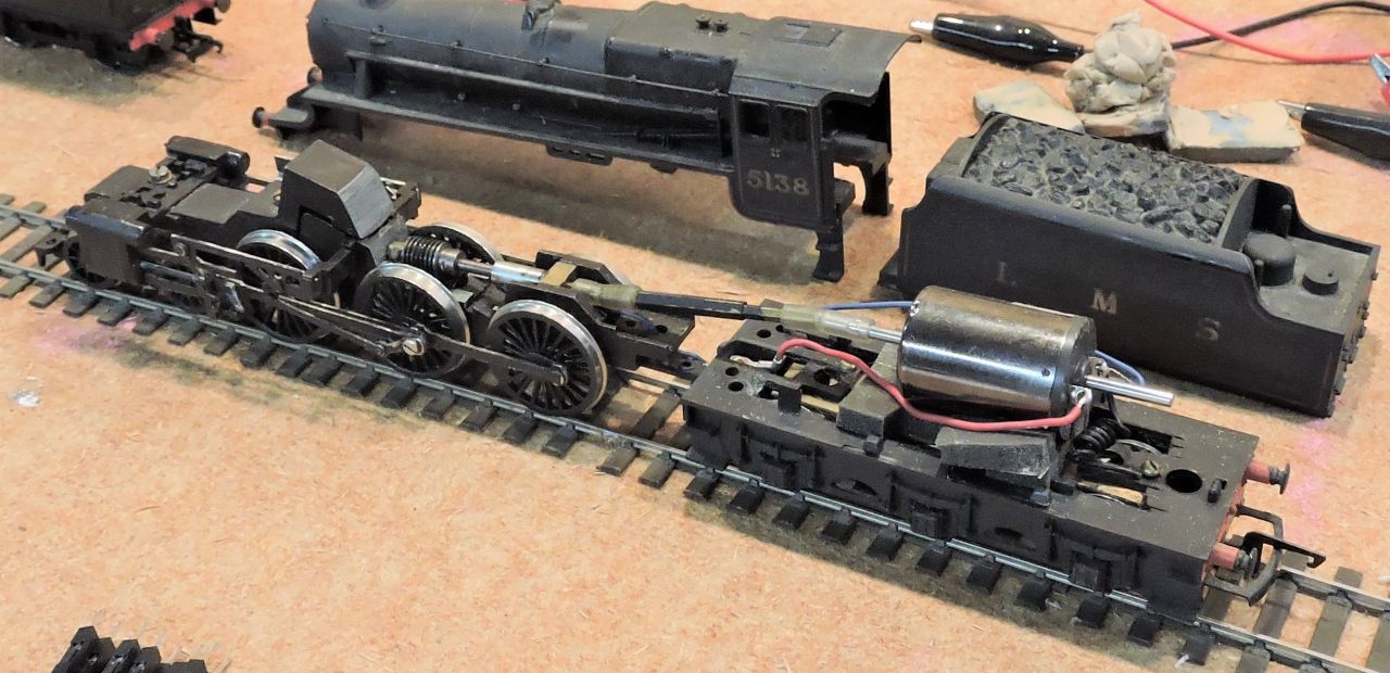 This one has the more conventional worm drive the the center axle. I think that's a 40:1 Romford which is a bit too much reduction for that motor. The top speed is too low but it is relentless and quite quiet too. The drive shaft consists of two concentric hexagonal brass tubes that can slide to accommodate changes in length. The "universal joints" are actually pieces of thin-wall silicone model aircraft fuel line. Crude, but effective. The tender chassis is a solid lump of square brass. Cheers! Andy |
||
|
posted: 12 Oct 2019 15:47 from: Andrew Duncan
click the date to link to this post click member name to view archived images |
Thanks Nigel Brown wrote Hello NigelThere was the well documented case of the GWR / LNER exchange trials pitting Castles against the A1 pacifics, around 1925. One morning, the LNER upper echelons gathered at King's Cross to watch a Castle attempt to haul an express out of the station and up the bank, a notorious task which even Gresley's pacific had big trouble with. Cue much joking as to the eventual outcome amongst watchers. Then silence as Collett's masterpiece glided out of the station and disappeared up the bank with scarcely a hitch! It’s interesting that that you talked about 4-4-0 being a pain to get running well and that your solution is full compensation. I’ve an old K,s Bulldog which ran like nothing on earth, nose down like a terrier looking for rabbits. Under Iain Rice’s close supervision I built my first scratch built chassis for it but still with the driven wheel fixed. This improved things a lot but despite ( or maybe because of ) its cast body it’s still doesn’t have a lot of pulling power. That was 10 or 15 years ago. Then in more recent times I attempted a Finney curved frame one. I chose to make this fully compensated and in fact as I built the chassis I carved up sheet lead to fit in every nook and cranny within it that wasn’t filled with pick ups and compensation beams. This has resulted in a very sure footed loco and with pick ups on the the bogie as well it’s a pretty reliable runner and has better pulling power than the Ks one, primarily I suspect because there isn’t a white metal boiler sticking out miles in front of the driving wheels. But maybe the full compensation and lead low down, play their part as well. Certainly it seems to glide over my imperfect track in a way that’s really very beguiling. Thanks for your posts and whilst I think of it , talking of side control I was interested in your comment about the friction in the slot for the front bogie pivot. I’ve not looked at it for several years now but I think my Finney one has something similar. I’ll see if I can find a photo of the loco in question Kind regards Andrew |
||
|
posted: 13 Oct 2019 23:18 from: Andrew Duncan
click the date to link to this post click member name to view archived images |
Hello everyone Not a lot of progress I’m afraid this last week or so. Being in retail this is our busy time of year so as things are far from easy I’ve been distracted by non railway stuff. This evening I managed to cut up the bases that I stick the servos to, when top mounting them. I have got the tie-bars connected up to both the switches and the control rod. Now just need to stick the servos to their bases, screw them in place, connect them up to the control rods. Just looked for photos of my Bulldog but couldn’t trace them...but I will. Kind regards Andrew |
||
|
posted: 27 Oct 2019 23:46 from: Andrew Duncan
click the date to link to this post click member name to view archived images |
A little bit more progress this evening After spending the last fortnight including most of today building shelving and shelving units for one of our shops I allowed myself some time off late this afternoon to indulge in a little Yeovil-ing. At some point recently I’d cut out about a dozen servos bases from 30 or 40 thou plasticard. As in the photo below. 2787_271834_370000000.jpg 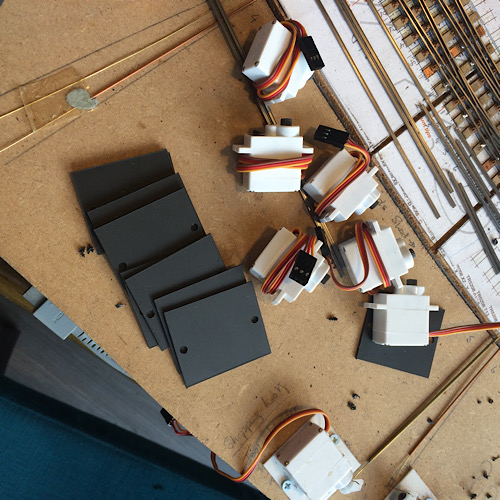 So this afternoon I stuck all the servos needed for this board to their bases, screwed them in place and connected up the control wires from the turnouts. I think I may need to use thicker wire than the 0.4mm stuff that I have used, it’s a bit too flexible in some cases! 2787_271845_520000000.jpg 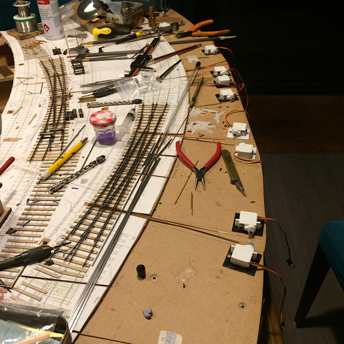 Next I must get on with building the remaining turnouts on this board. To day at some point I found myself reading a couple of loco building threads on RM web and realised how much I miss stock building and locos in particular, not having done any for four or five years I’m beginning to get withdrawal symptoms! Onwards and upwards I hope! Kind regards Andrew |
||
|
posted: 28 Oct 2019 00:47 from: Rob Manchester
click the date to link to this post click member name to view archived images |
Hello Andrew, Yes, it can be a nuisance when work gets in the way of play I can't remember if you posted a list of the loco, coach and wagon stock you intend running. Have you been buying suitable kits and locking them away for a rainy day ? What are you planning for couplings and rolling stock compensation systems. Those two areas always cause me the most headaches for UK prototypes...with my US HO and narrow gauge projects the couplings are Kadee knuckle types ( which are both realistic and operationally friendly ) and as the rolling stock is all with bogies ( sorry trucks ) they run well with a little slop at each end. Hope the work bits are going well for you Regards Rob |
||
|
posted: 28 Oct 2019 06:28 from: Andrew Duncan
click the date to link to this post click member name to view archived images |
Rob Manchester wrote: Hello Andrew, end.Hello Rob You’re quite correct, work does get in the way of playing but I’m in the fortunate position of enjoying my work just as much as the play. Retail is quite a challenge at the moment going through, as is I suppose patently obvious, the biggest challenges it’s probably ever experienced. That is trying to understand and cope with the internet! To do this I believe one needs a strong, lively and dedicated team of people who love what they’re doing and are motivated by strong interest in the product ( Cookware and the end result food, in our case) and the success of the company. And importantly who really enjoy working with each other. A combination of good luck and taking our time when choosing new people has really helped us meet this challenge. So sorry I’ll get off my soapbox now, but as you can probably tell from various conversations we’ve had in recent times I can get as obsessive about what makes good business as I can about tiny trains! As to making a fortune, well that’s a relative term. We’ve had some good times and some very difficult ones. Two years ago Babette and I were seriously discussing selling the house if things got any worse. Fifteen or twenty years ago we actually considered buying a second house in France( like the first option neither have so far happened). Quite a contrast! So to finish things seem to be easing now and hopefully will continue to do so. Thanks for asking. Now back to the Great Western Railway, Yeovil in 1922. Back in 2002 I asked Iain Rice to help me build a model of Maiden Newton (45mins down the road from Yeovil Pen Mill) which we did in 00 and in the process he also taught me how to build a really smooth running loco chassis. Later we added a very very cut down version of Yeovil. And so when I decided, on a whim really, to convert to EM, as I had already made a good start on building the rolling stock for the Weymouth line for the year 1922 I thought I’d just build Yeovil again but a lot closer to scale( 21’ instead of 10’) So thanks for your questions and if I may, I’ll break off now and finish answering your questions later today when I’m back from my day job! Kind regards Andrew |
||
|
posted: 28 Oct 2019 21:21 from: Rob Manchester
click the date to link to this post click member name to view archived images |
Hello Andrew, Thanks for the work insight - it must be difficult getting the decisions right Look forward to the play update when you have time. Rob |
||
|
posted: 28 Oct 2019 22:02 from: Andrew Duncan
click the date to link to this post click member name to view archived images |
Rob Manchester wrote: Hello Andrew,Hello again Rob "Have I been buying suitable kits and stashing them away under the layout" ....is the Pope a railway enthusiast....yes I fear that I have succumbed on many many occasions to buying small brown boxes just full of exciting brass etchings or intricate plastic mouldings . So unless I live to a hundred or so the pile under there will probably defeat me ! But never mind every time I look at them my mouth salivates at the thought of what delicious contents they have, and I have to resist the urge to sit down and start fishing them out and steadily inspect the contents of each box one after another! As to suspension systems I'm not a fan,locos apart, because of the work involved. On locos though I've always compensated as I was taught by Iain with one rigid axle. Recently on a Finney Curved frame Bulldog and a Mitchell Mogul I installed full compensation which I must say I think is worth it as it produces a silky smooth ride....very nice. Having said that I find the thought of continuous springy beam also fascinating and find myself tempted to experiment with that at some point. I use brass wire or nickel silver or phosphor bronze for pickups, so no split frame stuff here. Don't think I'd have the skills or the patience to get it working ok. Coupling wise I'm thinking of using the old Sprat and Winkle which is probably reasonably reliable, that or go the pragmatic route that you mentioned and use Kadees. Or use a mix? S&W for goods and Kadees for coaching stock? As to locos then that's easy because in 1922 Yeovil shed had a Dean Goods, a mix of panniers including outside framed Buffalo's, a Metro or two, that odd class of 4-4-0 that looked like someone had made a bad model of a Bulldog, and there were some 517 somewhere not far as well as Bulldogs, curved, straight and bird ones(got a nice Finney Bird just crying out to be started!) based down at Weymouth. At present I think I've got 5 or 6 panniers / saddle tanks/ Buffalos built and working, two or three Moguls a Dean Goods, a Hall (far too modern unless maybe I renamed it Saint Martin ?) a large Prairie 31xx , a couple of Bulldogs and an Aberdare also, but all in 00 at present. Coaching stock is not plentiful in terms of completed models but there's a smattering of Slater's, a brass toplight or two, Slater's Dean clerestory and brass clerestory or two. But under the layout plenty awaits construction! Well I think thats about my lot for tonight. Kind regards Andrew |
||
|
posted: 29 Oct 2019 00:41 from: Rob Manchester
click the date to link to this post click member name to view archived images |
Hi Andrew, Thanks for the 2nd update. Most of my stock of locos ( GW as well as others ) is RTR offerings that will be 'upgraded' with better wheels ( that will fit my EM-SF standard I wasn't suggesting you used Kadee couplings - I think that would not be a good choice for Yeovil. I was just making the point that US modellers have the choice made for them as the Kadee is excellent from both an operational and visual angle. Spratt and Winkle is in my view the best choice for hands-off operation - I tried the Alex Jackson system but can't say I was impressed ( glad I didn't say that on RMWeb I have a few of the Slaters Dean coaches but could do with a few more unmade kits. Since the 'mess up' with Coopercraft they aren't easy to find. Any spare let me know - if you want to reduce the pile of unmade kits! Thanks again for your jottings. Rob |
||
|
posted: 29 Oct 2019 06:50 from: Andrew Duncan
click the date to link to this post click member name to view archived images |
Rob Manchester wrote: Hi Andrew,Hello RobOh yes I forgot decoders. Like you I put in sound and have found ESU to be pretty good but Zimo motor control is better and the combination of a coreless Maxon motor and a Zimo is just mouth watering when I can fit them all in. Talking of which the culmination of cramming stuff into a loco has for me to be my 517 0-4-2 ( a Gibson cast kit) which from memory has an ESU sound chip a small 10 series Mashima and getting that into the space available was a bit of a challenge! I didn’t take your thoughts on Kadees to be recommendation, just your experience. But I have often thought of them as at least a partial solution on coaching stock, they are just so neat! One downside to this is the need for well thought through loco fleet, some with Kadee and some with S&W. I’m also interested in your experience with them, as to why they might not be good and indeed your positive experience with the 3mm(?) S&W ( with delayed uncoupling?). Any guidance here would be most welcome as my experience with both is non existent. I also have not tried Jackson’s but feel that they are probably best left to those P4 “Engerneers” who seem to make the impossible possible. Until next time Kind regards Andrew |
||
|
posted: 29 Oct 2019 09:15 from: Jim Guthrie
click the date to link to this post click member name to view archived images |
Andrew Duncan wrote: Rob Manchester wrote: I didn’t take your thoughts on Kadees to be recommendation, just your experience. But I have often thought of them as at least a partial solution on coaching stock, they are just so neat! One downside to this is the need for well thought through loco fleet, some with Kadee and some with S&W. I’m also interested in your experience with them, as to why they might not be good and indeed your positive experience with the 3mm(?) S&W ( with delayed uncoupling?). Any guidance here would be most welcome as my experience with both is non existent. In the S Scale Society a lot of us used the Spratt & Winkle coupling and it worked very well with excellent reliability. But we did make our own from thin brass wire and when these were blackened they were pretty well invisible. Delayed uncoupling "fingers" also worked very well. However we did make stock one-ended with the hook on one end and the loop on the other. We had found that we occasionally got hooks on double-ended setups entangled. A loop on one end also allowed buffers to work. This was never a great problem since there were no known S scale layouts with a reversing section. Jim. |
||
|
posted: 29 Oct 2019 20:50 from: Rob Manchester
click the date to link to this post click member name to view archived images |
Hi Andrew, The main reason not to use Kadees is simply appearance and prototype fidelity. On coaches ( especially ones with interconnecting gangways ) it isn't so bad but ironically the stock you want to shunt and re-couple most are the little wagons and they just don't cut-it for me when fitted with Kadees although I can live with modern-ish airbraked BR wagons being so adapted. There are some mounting plates for S&W couplings available here that work well although you can get the 'original' type from Andrew at Wizard There is a Youtube video here you may not have seen. I have a mix of ESU and Zimo sound chips. Bearing in mind I have UK and US models I seem to have amassed a mixed range going back a number of years. I think I will be trying to use the ESU ones in US locos as the sound files are free from the ESU site and I have the programmer required to re-blow them. Some of the Zimo ones available now are very small - just as well seeing the size of some of the locos I have to put them in Rob |
||
|
posted: 29 Oct 2019 22:55 from: Phil O
click the date to link to this post click member name to view archived images |
Hi Andrew, First MERG supply their servo mounts with 1mm piano wire for turnout operation. In the club all our exhibition layouts use Sprat and Winkle couplings. I would say that they are around 95% reliable, usually after setting up the layout and getting a brew the next job is to check the couplings against a gauge, this is not totally infallible as different members have set the pivot point in slightly different places, we are now using the etched mounting plates which is improving standardization and reliability. Any rogue vehicles are removed at the earliest opportunity and rechecked,if they persistently give trouble they are put in the naughty box for attention back in the club. Cheers Phil. |
||
|
posted: 29 Oct 2019 23:19 from: Nigel Brown click the date to link to this post click member name to view archived images |
I used Kadees on my long-departed U.S. HO layout, part of which seen here:528_291806_400000000.jpg Had mixed feelings about them. One thing was the uncoupling magnets were rather unsightly; you can see an electromagnetic one by the station building on the right of the picture. Another thing was I didn't find them as operationally foolproof as sometimes claimed; if you use them with unweighted freight cars such as off-the-shelf Athearn of the day I found that when trying to couple up there was a tendency for the cars to bounce apart rather than couple. I think on the right sort of layout where you only need a few uncoupling points and where you've paid a lot of attention to getting the cars correctly weighted and the coupling aligned carefully they'd be OK. I use 3mm B&B couplings, which I like a lot. They're best if you have the sort of layout where you can put just half a coupling on each end of a wagon. They're unobtrusive, and work well with various electromagnets, such as the Seep ones where you just need to drill a hole between sleepers and then push the shaft of the magnet up from below. Nigel |
||
|
posted: 29 Oct 2019 23:23 from: Andrew Duncan
click the date to link to this post click member name to view archived images |
Hello Jim Good to hear from you. Thanks for your feedback on Spratt & Winkle couplings. I’m with you on the hooks getting tangled. The coupling we adopted on the old layout, Iain’s “Imprecise”, would do that where two hooks weren’t quite set up correctly....sometimes drove me bonkers. So to avoid it with hooks at one end seems very sensible to me. Does that mean your locos always have hooks both ends? Kind regards Andrew |
||
|
posted: 29 Oct 2019 23:39 from: Andrew Duncan
click the date to link to this post click member name to view archived images |
Phil O wrote: Hi Andrew,Hello Phil Thanks for your info on the Merg servo mounts. The reason Im using much thinner wire is because I want some flexing/ sprinting in the motion ( like the old fashioned omega spring) to keep a bit of pressure on the switches when thrown. This is produced by bending the end of the control wire through 90 degrees at the point where it’s about to connect to the servo horn and then another 90 degree bend at right angles to the first that goes through the horn arm itself. 1mm would be too thick but I think I might try .5 or .6mm and see if that gives the right balance of spring and shove! Thanks also for your experience on S&W...seems to be becoming a common theme! Kind regards Andrew |
||
|
posted: 29 Oct 2019 23:57 from: Andrew Duncan
click the date to link to this post click member name to view archived images |
Nigel Brown wrote: I used Kadees on my long-departed U.S. HO layout, part of which seen here:528_291806_400000000.jpgHello Nigel A dissenting voice amongst the pro Spratt & Winklers! I once saw a 4mm layout with B&B’s which did a lot of shunting I must say it worked beautifully and without fault. Maybe I need to experiment a bit with both? Thanks for your thoughts and experiences Kind regards Andrew |
||
|
posted: 30 Oct 2019 01:15 from: roythebus
click the date to link to this post click member name to view archived images |
I've used Kadees since the early 1980s, first on my HO German layout, and today on my BR-ish layout. Providing they're adjusted to the correct height they work perfectly most of the time. I'm currently fitting the Kean systems close-couplings to coaching stock and use Hornby and Roco KK units. the Kean units require a centring spring to make sure they return to centre when used with Kadees. As for uncoupling magnets, the Folkestone club use a couple of miniature round magnets mounted diagonally in the track. They're almost invisible but do require accurate stopping by the driver! Kadee also do under the track invisible magnets. |
||
|
posted: 30 Oct 2019 01:16 from: roythebus
click the date to link to this post click member name to view archived images |
PS I now buy Kadees in bags of 50, they're a lot cheaper that way! | ||
|
posted: 30 Oct 2019 23:23 from: Andrew Duncan
click the date to link to this post click member name to view archived images |
roythebus wrote: I've used Kadees since the early 1980s, first on my HO German layout, and today on my BR-ish layout. Providing they're adjusted to the correct height they work perfectly most of the time. I'm currently fitting the Kean systems close-couplings to coaching stock and use Hornby and Roco KK units. the Kean units require a centring spring to make sure they return to centre when used with Kadees.Hello RoyThanks for your experience of Kadees, I also think that they have some very practical sides to their adoption. Do you have experience of mounting them on kit built wagons and coaching stock which don’t have pockets to plug them into? Kind regards Andrew |
||
|
posted: 31 Oct 2019 16:57 from: FraserSmith
click the date to link to this post click member name to view archived images |
The solution to having waggons etc pulled or held by permanant magnets is to mount them on a fairly long arm attached to a servo. Then they can be dropped down from their active position when not wanted. In the active position they could be almost below the sleepers if a suitable hole through the baseboard is made for them and covered with light card prior to ballasting. They can then be as effective as electromagnets but without the big current required to keep the electromagnets active. Fraser |
||
|
posted: 31 Oct 2019 21:51 from: Rob Manchester
click the date to link to this post click member name to view archived images |
Hi Fraser, My solution is a little more dramatic. I replace the pinpoint axle from Gibson wheels ( or other brands ) with a brass one and make sure the wagons are weighted to around 40-60 grams depending on size. I hate pinpoint axles, whatever I do to make them fit properly they never seem to stay a good fit between the axleguards by the time you have taken them out for painting etc. I use a system similar to the old Exactoscale wagon wheels with a 2mm hollow brass tube that carries the wheels. This fits exactly between the axleguards and runs on a 1.6mm brass rod that is inserted from the side before the axleboxes are attached. There is a 1.6mm diameter bush in each axleguards. Result = no slop and a perfect fit. I use it with rocking w-irons from various sources and Bill Bedford sprung items depending on the wagon type. Rob |
||
|
posted: 1 Nov 2019 00:21 from: Andrew Duncan
click the date to link to this post click member name to view archived images |
Hello again Nigel I realise that you were referring to Kadees not Spratt & Winkles above when you said you weren’t altogether convinced about them. Somehow I missed that first line of text above the photo! Apologies Andrew |
||
|
posted: 2 Nov 2019 01:32 from: Andrew Duncan
click the date to link to this post click member name to view archived images |
FraserSmith wrote: The solution to having waggons etc pulled or held by permanant magnets is to mount them on a fairly long arm attached to a servo. Then they can be dropped down from their active position when not wanted. In the active position they could be almost below the sleepers if a suitable hole through the baseboard is made for them and covered with light card prior to ballasting. They can then be as effective as electromagnets but without the big current required to keep the electromagnets active.Hello Fraser Interesting ,and dare I say predictable with your background, that you should suggest such an idea. Iain made a “ clockwork “ version ( very Rice)on Yeovil Mk1 for me. He mounted a S&W magnet on a hinge at one end and connected it to simple rod terminated on the edge of the baseboard with end turned through 90 degrees to make a crude handle. So I could raise or lower the magnet at the flip of a rod. Can’t remember what kept it up, some sort of steel stop I think. But anyway it worked and stopped accidental uncoupling. Thanks for your thoughts. Kind regards Andrew |
||
|
posted: 2 Nov 2019 12:50 from: Nigel Brown click the date to link to this post click member name to view archived images |
Andrew Duncan wrote: Hello again Nigel One thing I've found with magnetically operated couplings, it's a mistake to use simple permanent magnets on running lines. They uncouple when you don't want them to just enough to be irritating. I'd suggest using electromagnets, or permanent magnets operated mechanically as others have suggested. In other circumstances permanent magnets are fine. I use a cassette based fiddle yard with separate cassettes for locomotives and stock, and the stock cassettes have a permanent magnet near the end furthest away from the layout. I found some small neodymium magnets on Amazon at remarkably cheap prices (about £6 for 50) which are fine. Only thing is to make sure they're not too powerful; I use ones 3mm diameter and 1mm thick, much larger ones can have unfortunate effects! Nigel |
||
|
posted: 3 Nov 2019 21:03 from: Andrew Duncan
click the date to link to this post click member name to view archived images |
Nigel Brown wrote: Andrew Duncan wrote:Hello NigelOne thing I've found with magnetically operated couplings, it's a mistake to use simple permanent magnets on running lines. They uncouple when you don't want them to just enough to be irritating. I'd suggest using electromagnets, or permanent magnets operated mechanically as others have suggested. Thanks for your thoughts on where to permanent magnet and where not to. On the old layout of Maiden Newton I had the same problem with the brake van sometimes uncoupling on the main line which as you say was irritating. When it comes to it, I’ll take a look at EBay as a source of cheap magnets, As promised after you posted a picture of your 3mm Dukedog, heres my Bulldog built in 2010 in 00 in a somewhat embryonic state. Surprisingly sure footed for a 4-4-0 because of the full compensation and well distributed weight. I’ll post a more complete picture when I can find it. The white rectangle in the smoke box incidentally is the speaker and in fact at one stage I had all the electronics in the loco itself. I can’t remember now but I’ve a feeling that I’ve since moved the decoder to the tender. 2787_031554_070000000.jpg 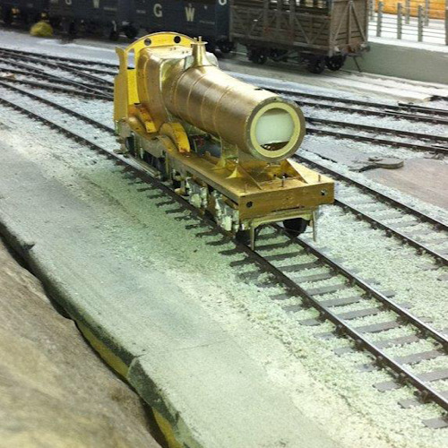 Kind regards Andrew |
||
| Last edited on 3 Nov 2019 21:05 by Andrew Duncan |
|||
|
posted: 3 Nov 2019 21:09 from: Matt M.
click the date to link to this post click member name to view archived images |
Hi Andrew, I remember an old 'Model Railroader' article about making your own electro magnets to overcome this problem. It was back in the late 70's. Don't ask me which issue as I don't have any from that vintage on my shelves. I think they were winding coils around nails. Matt M. |
||
|
posted: 3 Nov 2019 22:19 from: Andrew Duncan
click the date to link to this post click member name to view archived images |
Matt M. wrote: Hi Andrew,Hello MattThat sounds very Peter Dennyish, very 60’s and 70’s! I’m pretty certain I saw something similar in an old Railway Modeller of the same era? Think I’ll go for the ones that Wizard sell probably? Kind regards Andrew |
||
|
posted: 4 Nov 2019 07:34 from: Stan Agar
click the date to link to this post click member name to view archived images |
Having been involved with American HO for longer than I care to remember I have found that a kebab stick cut at an angle or a well-worn small screwdriver are fine for uncoupling at up to 2 feet from the baseboard edge, using magnets only for out of the way places like under overall roofs etc. On a variety of layouts I have only ever installed a handful of uncoupling magnets. Kadee make an electro magnetic uncoupler but it’s a bit of a beast. I have had success with permanent magnets hinged on a wooden ‘trap door’ and operated by a bent coat hanger or a piece of string (rather Peter Denny style). | ||
|
posted: 4 Nov 2019 07:49 from: Bernard Haste click the date to link to this post click member name to view archived images |
David Yule used Peco point motors cut in half as solenoids for uncoupling ramp operation on his model of Disentis. They were violent in action and could derail a vehicle. I now part own the layout and we are looking at using servos with controlled amount of lift AND controlled speed. We are also looking at the ability to leave the servo in the up position to act as a brake on uncoupled stock. There will be an illuminated switch on the control panel to indicate when the servo is up for safety reasons! Bernard |
||
|
posted: 4 Nov 2019 08:31 from: Nigel Brown click the date to link to this post click member name to view archived images |
Matt M. wrote: Hi Andrew, Matt M.Think this was quite widely done at the time. There was a lot of knowledge floating around then about what gauge wire to use and how many turns. One problem I found on my US layout was indeed permanent magnets having an adverse effect on rolling stock rolling. As far as I can remember it was on some of the old Athearn stock which may have had steel axles. For a similar reason had to be careful with the size of the neodymium magnets on my current layout; too powerful and they could grab the stock. Nigel |
||
|
posted: 4 Nov 2019 09:07 from: Jim Guthrie
click the date to link to this post click member name to view archived images |
I am being reminded of experiments I carried out over ten years ago to get good working uncouplers on my N scale American layout. I had tried permanent magnets with mixed success and tried electromagnetic uncouplers but used the coils and pole pieces from old Carpenter relays. The pole pieces are "U" shaped with a coil on each leg. I positioned each pole at the tracksides in the same way as the Kadee electromagnetic product and success was a bit limited, and was only improved when I fed the relay from what was, effectively, a capacitor dishcarge circuit. The relays worked on 50V (ex GPO) and my circuit gave a start pulse of about 75V before settling to 50V, and the uncoupler worked very well. I'm just about to start work again on that layout after about eleven years so I'll have to dig out all my experiments to get things working again. Jim. |
||
| Last edited on 4 Nov 2019 09:08 by Jim Guthrie |
|||
|
posted: 4 Nov 2019 22:29 from: Andrew Duncan
click the date to link to this post click member name to view archived images |
Hello Stan, Bernard, Nigel and Jim Thank you all for your various experiences and experiments with magnetic uncoupling. I will let you know how I get on with probably the S&W and it’s coupling properties as time progresses. Don’t hold your breath though as there’s quite a way to go! Kind regards to you all. Andrew |
||
|
posted: 5 Nov 2019 08:39 from: stuart1600
click the date to link to this post click member name to view archived images |
Nigel Brown wrote: .......I found some small neodymium magnets on Amazon at remarkably cheap prices (about £6 for 50) which are fine. ......At risk of hijacking Andrew's thread...... Is there an issue with polarity of magnets for use with Kadees? I seem to recall reading something about this in the model press some time ago. I found some neodymium magnets on ebay which are described as being N and S on opposite faces - are these satisfactory for this use? Any guidance appreciated. Kind regards, Stuart |
||
|
posted: 5 Nov 2019 11:25 from: Andrew Duncan
click the date to link to this post click member name to view archived images |
Interesting question Stuart. I dont know the answer but I'm sure someone will.... Kind regards Andrew |
||
|
posted: 5 Nov 2019 11:35 from: Jim Guthrie
click the date to link to this post click member name to view archived images |
stuart1600 wrote: Is there an issue with polarity of magnets for use with Kadees? I seem to recall reading something about this in the model press some time ago. I found some neodymium magnets on ebay which are described as being N and S on opposite faces - are these satisfactory for this use? Any guidance appreciated. Stuart, The magnetic field generated by the magnet(s) for the Kadee operation should lie across the track - i.e. N by one rail and S by the other. The Kadee magnet is a flat, plate magnet which is polarised across the plate so that when placed under the track, the opposite poles are under the rails. If you are using separate magnets on each side of the track, like small neodymium ones, then you have to make sure that opposite polarities are pointing upwards so that it's N on one side and S on the other. You can check out the poles by using the "like poles repel, unlike poles attract" logic. Electromagnets should effectively have a "U" shaped pole piece with the ends under the rails. Jim. |
||
| Last edited on 5 Nov 2019 11:43 by Jim Guthrie |
|||
|
posted: 5 Nov 2019 12:12 from: wcampbell23
click the date to link to this post click member name to view archived images |
The East Kilbride Model Railway Club used the Kadee electromagnets on one of their 00 layouts and the pictures below show the installation. 54_050703_290000000.jpg 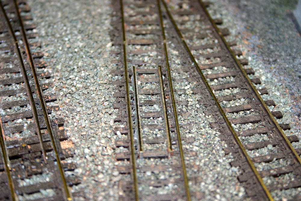 The poles look a bit like like checkrails and so are not very obtrusive. A rectangular hole was made in the baseboard and then sleeper offcuts and ballast were used to bed in the poles of the electromagnet. The next picture shows the installation on the underside of the baseboard. A bracket has been used as the Kadee method of installation was not suitable for us. 54_050707_120000000.jpg 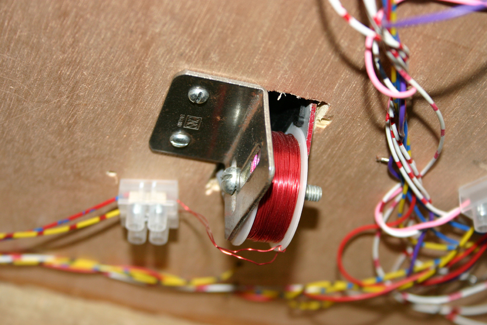 Another coupling option that has not been mentioned so far is the Dingham system. These are similar to B&B in operation and are intended to be single-ended. They are mounted in the coupling slot of a rail vehicle and are quite discrete. The website is: http://www.dingham.co.uk/index.html Regards. |
||
|
posted: 5 Nov 2019 12:28 from: stuart1600
click the date to link to this post click member name to view archived images |
Thanks, Jim. That's very helpful. I had a feeling that the Kadee magnets were polarised across the track, but hadn't had the wit to realise that this could be achieved by using two of the small magnets at each uncoupling location. |
||
|
posted: 5 Nov 2019 14:10 from: Andrew Duncan
click the date to link to this post click member name to view archived images |
Hello Thanks for thoughts about the Dinghams, Id forgotten just what a neat design they are. Another one for the consideration pile! Kind regards Andrew |
||
|
posted: 7 Nov 2019 10:50 from: Stephen Freeman
click the date to link to this post click member name to view archived images |
Having used used both B&B/D&G and S&W couplings, I found both worked but S&W were more difficult to fit, though easier to make. On the whole my preference would be for B&B. | ||
|
posted: 9 Nov 2019 19:31 from: Andrew Duncan
click the date to link to this post click member name to view archived images |
Hello Stephen Thanks for your thoughts as well. I must admit to being rather taken with the Dingham coupler looks even if it does look a bit of a fiddle to build. Think I'll acquire a pack and try them out. I really don't know what I'm doing getting all excited about couplers at the moment, I've got no railway working to run anything on and no stock converted to EM to put on it. Daft but fun! Kind regards Andrew |
||
|
posted: 10 Nov 2019 18:19 from: Andrew Duncan
click the date to link to this post click member name to view archived images |
Hello everyone I’ve been in touch with John (The Laird) over on RM web and he’s sent me his latest incarnation of signal servo tower which I first came across this time last year on his thread Leeds City, the Midland Side. The first samples he sent me were in 2mm MDF which I showed back on page 6. He’s now moved to a neater stronger material in the form of Perspex. Photos are below and he’s improved the design in enabling removal from the baseboard easier. I’m really excited by this development and am wondering if I can discipline myself to do the signalling as I go along rather than coming back to it later or worse as an afterthought. 2787_101219_460000000.jpg 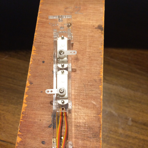 This is the front view of the tower and you’ll need to imagine a two arm signal sticking out the top of it. This narrow single version will hold 3 servos and therefore operate up to three signals arms. There is a double width version which takes 6 servos. Impressive amount of operational power in a tiny amount of space. A great piece of design and I’m indebted to John for his help and willingness to share his design And here’s the same one side view. 2787_101226_330000000.jpg 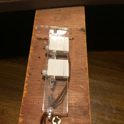 Back to baseboards. There’s a downside to surface mounted wiring. As you can see from this photo there’s almost more brass tube topside to take the wiring than there is cork sheet! But as soon as I begin to doubt the wisdom of this approach I remember what it’s like on all but the last baseboard (which also has surface mounted wiring) and am greatly relieved that I can see everything at a glance. And if that’s true for wiring then it’s all the more the case for topside mounting the servos....so much easier to adjust! Heres a picture 2787_101256_400000000.jpg 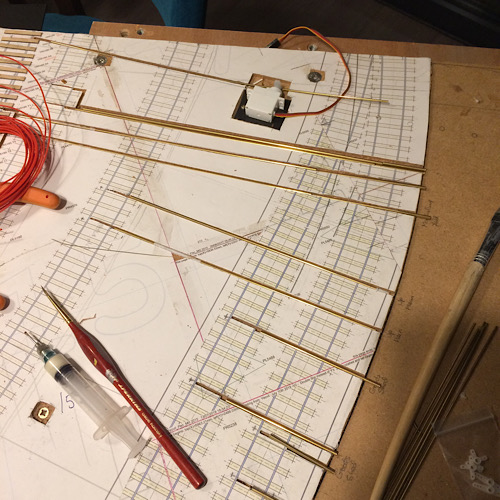 And here, apropos of nothing at all, is a 2011 photo of my Gibson 0-4-2 517 class that I came across the other day, just about to get its first coat of paint. Really worth the trouble of having models that unbolt into subassemblies for painting and maintenance. I’d forgotten that this was how I made this engine and I’m really glad as I’ve now somehow got to get EM spaced wheels into that very narrow body! 2787_101255_330000000.jpg 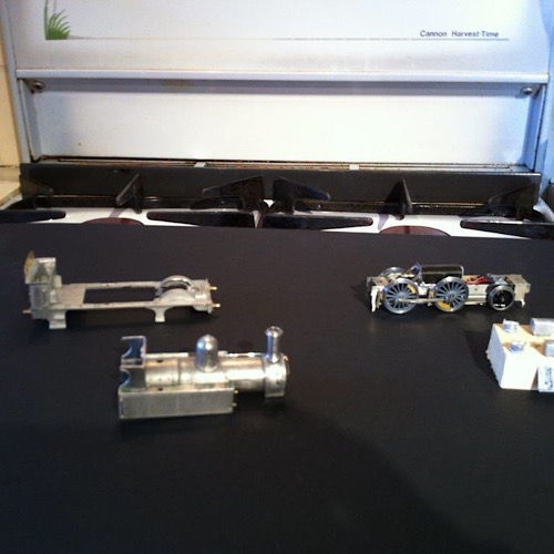 Well that’s it for now, back to track making! Kind regards Andrew |
||
| Last edited on 17 Jan 2020 18:30 by Andrew Duncan |
|||
|
posted: 10 Nov 2019 19:28 from: Stephen Freeman
click the date to link to this post click member name to view archived images |
Six servos sounds impressive,I have not as yet needed to exceed four as per The MERG design. I have found that tapping the horn 12BA I can use a short bit of brass tube soldered to the operating rod to make the signal easily demountable from the servo. I will try and post some photos tomorrow when I am back on the PC |
||
|
posted: 11 Nov 2019 10:24 from: Stephen Freeman
click the date to link to this post click member name to view archived images |
Tried to upload a photo but couldn't get it to work, referred to MW. | ||
|
posted: 11 Nov 2019 16:12 from: Stephen Freeman
click the date to link to this post click member name to view archived images |
I have now managed to upload the photo a different way. Hope it explains things.142_110453_230000000.jpg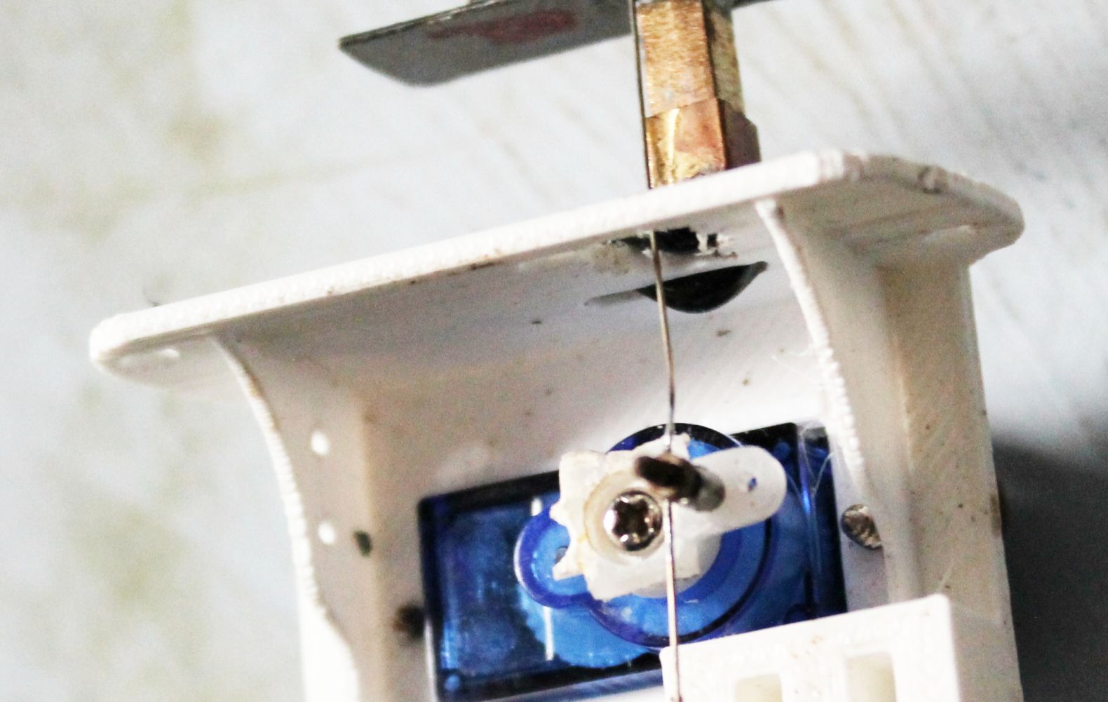 |
||
| Last edited on 11 Nov 2019 16:14 by Stephen Freeman |
|||
|
posted: 11 Nov 2019 20:09 from: Andrew Duncan
click the date to link to this post click member name to view archived images |
Hello Stephen Yup understood now. A neat way of getting adjustment from servo to signal arm. (edit) With the one that im going to use you can remove the whole thing, servo tower and signals attached, from above so the only the power cables to unplug. Kind regards Andrew |
||
| Last edited on 11 Nov 2019 20:14 by Andrew Duncan |
|||
|
posted: 13 Nov 2019 15:48 from: Stephen Freeman
click the date to link to this post click member name to view archived images |
Yes I very often do it that way but it's not really practicable in 2mm scale, it would make the signal base too big. Andrew Duncan wrote: Hello Stephen |
||
|
posted: 13 Nov 2019 21:06 from: Andrew Duncan
click the date to link to this post click member name to view archived images |
Stephen Freeman wrote: Yes I very often do it that way but it's not really practicable in 2mm scale, it would make the signal base too big.Hello Stephen I don’t know how wide it’s can be in 2mm but when I got home this evening I measured the single one that I photographed and it’s 12mm wide on top and needs a 10 MM wide hole in the baseboard as per the photos below. Is that still too wide? Kind regards Andrew 2787_131603_330000000.jpg 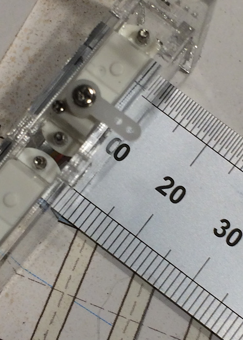 2787_131605_100000000.jpg 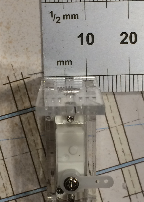 |
||
|
posted: 14 Nov 2019 20:36 from: Stephen Freeman
click the date to link to this post click member name to view archived images |
Depends. Most of the ones I have done in 2mm are less. | ||
|
posted: 1 Dec 2019 05:38 from: Andrew Duncan
click the date to link to this post click member name to view archived images |
I’ve been very busy at work in recent weeks and am finding my motivation difficult to rekindle. I’m not sure why but at the moment the thought of threading tiny plastic chairs on yards of steel rail doesn’t appeal! And I find myself reading threads on RM Web and EForum about loco builds, carriage and wagon building, signalling etc etc and wishing I was at that stage. Then I tell myself I’ve only got this baseboard to finish and the majority of the station is done. Well sort of. I’ve still got point rodding on the previous board to do and this one of course and on this one there is the North box, so there’s quite a lot of it. And then, now that I’ve got John’s Servo Towers, there’s the question of getting the signaling underway. After that there’s the conversion of all my 00 stock to EM. Sometimes I wish I’d been a little less ambitious and either stuck with 00, which would have saved a lot of time at some point in the future, or chosen a smaller prototype! And then most of the station needs ballasting! Sometimes I find myself thinking that I could make a small diversion and build a simple station using half a dozen of Peco’s new bullhead points in either 00 or EM, just to have something running and complete and not be left staring at 20 feet of incomplete station 6 years on! Well, Yeovil has been 4 years in construction so far, and it’s 6 years since doing any work on my old layout and I suppose I’m missing all the other aspects of construction that make our hobby so diverse and rewarding. So apart from finishing off laying in the last of the surface run wiring I’ve not done much recently and at the moment selling lots (I hope?) of pots and pans over the next three weeks is going to be pretty time absorbing. Kind regards Andrew |
||
|
posted: 21 Dec 2019 13:39 from: Tony W
click the date to link to this post click member name to view archived images |
Hi Andrew. I guess we all have moments like that, but the only way to achieve the impossible is to keep going. Yes, Looking forward can be daunting and there are so many distractions. I sometimes feel like I could do with three of me with all I wish to achieve. Breaking the task down into manageable steps is for me the way of getting there. Each step along the road brings its own rewards, but when one looks back it can be surprising how far one has come. Enjoy your Christmas and perhaps we can start the new year with 2020 vision. Regards Tony. |
||
|
posted: 21 Dec 2019 16:47 from: Hayfield
click the date to link to this post click member name to view archived images |
Andrew The thing is that you are now in a position that you can do what you want, you have track built so in theory you can have something moving, if you want to do some building or work on landscape, nothing stopping you Amongst other things I am building track, a couple of locos and the station building, just switch on which ever project/job I fancy Before this do have a great Christmas |
||
|
posted: 22 Dec 2019 23:15 from: Andrew Duncan
click the date to link to this post click member name to view archived images |
Tony W wrote: Hi Andrew.Hello Tony Wise words and thank you for your reply which I find quite comforting. Although I know it to be true that most, if not all of us, have these moments of “ blue funk” ( not sure where that came from!?) it’s good to hear that first hand that you’ve experienced the same sort of thing. And perhaps especially you with the size of project that your building, which makes mine look like a walk in the park! So thank you for your encouragement and a happy Christmas to you. I trust the new kitchen which I assume is finished(?) will be put to very good use in a couple of days time! Kind regards Andrew |
||
|
posted: 22 Dec 2019 23:41 from: Andrew Duncan
click the date to link to this post click member name to view archived images |
Hayfield wrote: AndrewHello John You are quite right of course I am in some ways only a stones throw from having 80% of the station runnable, even if not complete. So maybe I might relax my current determination to complete that last board and just start to get some of the more complete boards linked up and see if they actually still work. That will mean assembling a bank of switches to operate the area controlled by the north box. But that needn’t be too big a job. I’ll have a bit of think about what you and Tony have just said and see what occurs to me over the break In the meanwhile I’ve been clearing out the shed of lots of stuff and in process have given myself quite a lot more room. Room enough in fact to have my own work desk which I’ve just knocked up out of some phenolic coated 18mm ply. It’s on wheels, so easy to move around and has more 13amp sockets than you could shake a stick at. I see if I can find a photo and post it shortly. And lastly a very happy Christmas to you as well. Kind regards Andrew |
||
|
posted: 23 Dec 2019 00:00 from: Andrew Duncan
click the date to link to this post click member name to view archived images |
Hello Everyone As it’s Christmas and the end of the year I want to thank you for reading my meanderings over the course 2019 and if you’ve taken the time to reply then thank you for doing so. As a “lone modeller” it’s really very good to have the feed back and support that a forum like this one provides. So to Martin who dreamt up this wonderful program and to all of you, a very happy Christmas and a happy and peaceful new year. Here’s a picture of my new desk before I fitted 16 sockets to it and cluttered it up! Kind regards Andrew 2787_221856_550000000.jpg 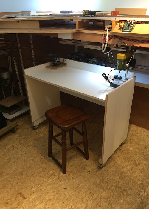 |
||
|
posted: 28 Dec 2019 00:35 from: Andrew Duncan
click the date to link to this post click member name to view archived images |
Hello everyone Sadly my old 00 model of Maiden Newton had to go to make way for my woodworking stuff. I’ve been using Yeovil’s shed as my workshop, but saw dust and tiny trains are poor bedfellows so eventually the thing I’ve been putting off for several years now had to be faced. And over the last week or so I’ve gradually been breaking up the old layout. Here are a couple of pictures Last picture before dismantling 2787_271921_570000000.jpg 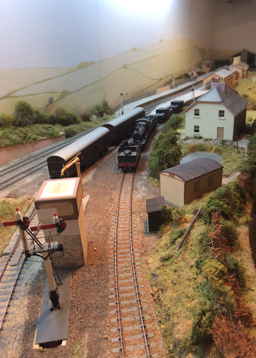 On the way to the dump! 2787_271919_140000000.jpg 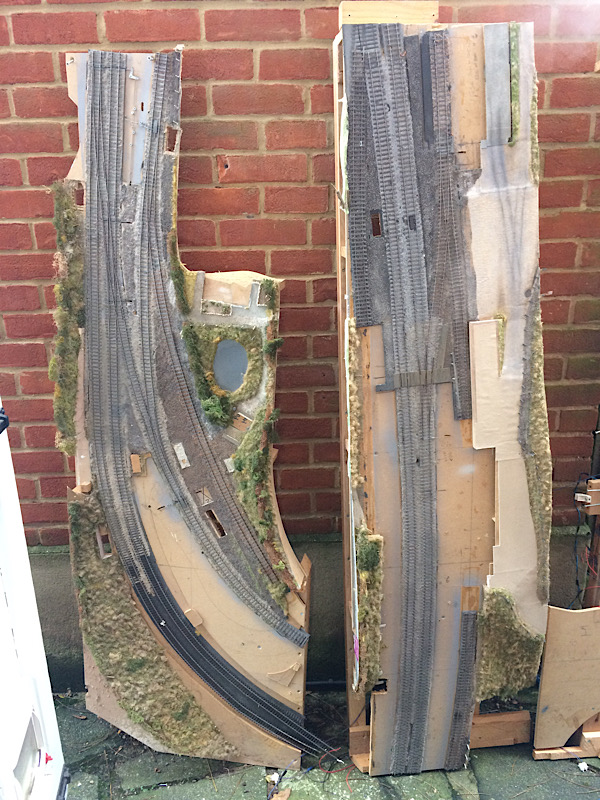 Jeanne, my middle daughter, and I a few days later, having just carried the bandsaw from the shed up the garden and down into the cellar, it’s new home. Heavy things bandsaws..... 2787_271928_520000000.jpg 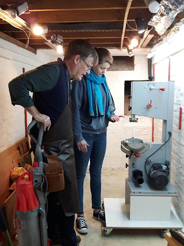 Sad though it was to see the old layout go I am looking forward to having all my big tools properly laid out. A place for everything and everything in its place.... at least that will be the aim. Kind regards Andrew |
||
|
posted: 28 Dec 2019 06:43 from: Andrew Barrowman
click the date to link to this post click member name to view archived images |
A place for everything and everything in its placeExactly what I say too Andrew although it's not exactly what I do. 2983_280134_460000000.jpg 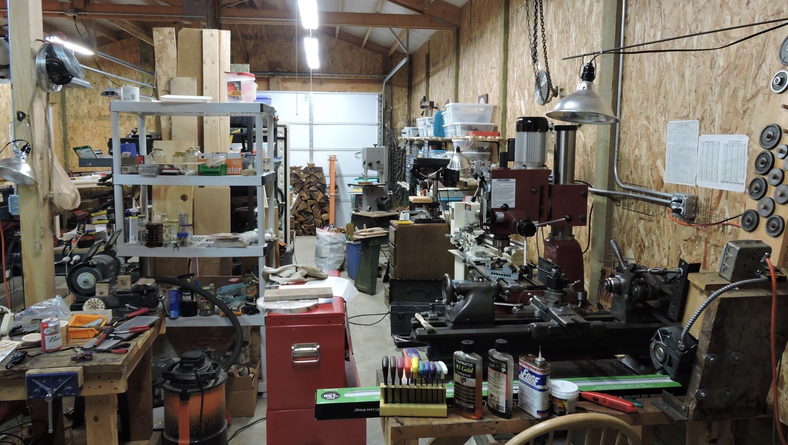 But I'm sure I'll do better next year Sorry to see the old layout go. Cheers! Andy |
||
|
posted: 28 Dec 2019 23:35 from: Andrew Duncan
click the date to link to this post click member name to view archived images |
Andrew Barrowman wrote: Hello AndyA place for everything and everything in its placeExactly what I say too Andrew although it's not exactly what I do.2983_280134_460000000.jpg Well that's a workshop and a half. Reminds me slightly of the photo Rob put up a year or so ago when we were discussing tools and how to manage them. If it wasn’t on this thread it might well have been on the one I did for my trolley in Share and Show? There can’t be many tools you don’t have by the look of it, although I didn’t spot a mitre saw, but it must be there somewhere.... 😜 Anyway thanks for the message and let us see the fruits of your labours when everything is just tickety-boo.... next year. Kind regards Andrew |
||
|
posted: 29 Dec 2019 06:32 from: Andrew Barrowman
click the date to link to this post click member name to view archived images |
Andrew Duncan wrote: Hello AndyHI Andrew, Yes, the mitre saw is out of sight behind the racking. There is also a table saw hiding behind the wood bandsaw and an arc welder under the layout baseboard on the other side of the shed. I've actually made a little progress in the last few days and managed to load and label storage drawers with most of the screws and nails that were laying around in random cardboard boxes. Precisely why I have quite so many varieties of nails and screws is a bit of a mystery but at least I'll be able to find the one I happen to need in future Cheers! Andy |
||
|
posted: 12 Jan 2020 00:27 from: Andrew Duncan
click the date to link to this post click member name to view archived images |
Andrew Barrowman wrote: Andrew Duncan wrote:Hello AndyHI Andrew, Andy That sounds good and doubtless by now the whole issue is just tickety boo? And by the way, the reason you have so many nuts, bolts, screws and nails is because when you want a certain size for a job you never have enough, so go and buy more, but they’re always cheaper in box’s of 200 so you buy those and of course have loads left over. Next time that size isn’t quite right for that project so you buy 200 more and so it goes on. I’ve been doing that for years and have an impressive collection now that almost rivals my collection of unbuilt kits.... Ok a change of subject. For several weeks now I’ve been fitting out my small workshop including investing in my first table saw which has taken me away from tiny trains for quite a while, but this afternoon the dinning room table once again played host to no.6 baseboard and I started to tidy up the surface run wiring at the rear of the board. And once this is in a substantially complete state I’ll start to tackle the turnout north of the single slip and finish off the slip itself. Below are photos of the workshop progress and no.6 board 2787_111914_250000000.jpg 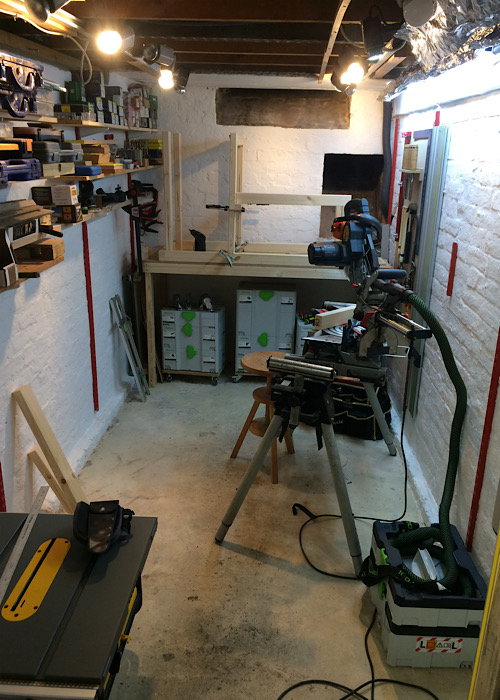 And here is the slightly tidier wiring at the rear of the baseboard that will be hidden by the goods shed and a low bank. 2787_111919_200000000.jpg 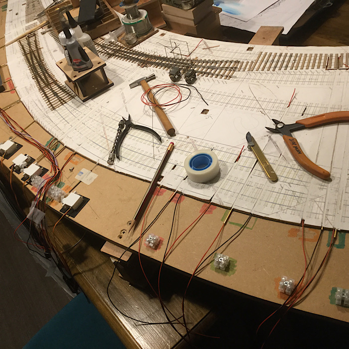 That’s it for tonight. Kind regards Andrew |
||
|
posted: 26 Jan 2020 23:13 from: Andrew Duncan
click the date to link to this post click member name to view archived images |
Hello everyone Firstly a very happy new year to you...a bit belated but better late than never. I’ve taken board no 6 down to the shed ( incomplete) and started to install it and boards 1-5 in situ. But first I removed them all and paid careful attention to the sub surface ( cheap construction ply....possibly a bit of a mistake? ) sanding flat any irregularities in the surface. I then remembered/ discovered that not all the “I beams” that hold he track boards 90mm off the sub baseboard were the same depth, varying by as much as 2.0mm ....not good for tiny trains so I’ve set about building up the height where necessary to achieve a uniform height. And then putting the boards back one by one and In the process I’ve been encouraging myself by positioning some of the old buildings from Yeovil mk1 on the layout to try to get a sense of achievement (!) and perspective. I took a couple of photos below Here’s a shot of the north end of the station (boards 5&6) with the signal box from my old Maiden Newton layout standing in the approximate position of the north box. It’s far too big and too modern but it’s a lovely model built mainly by Iain and it gives a sense of scale and a bit of atmosphere! 2787_280136_370000000.jpg 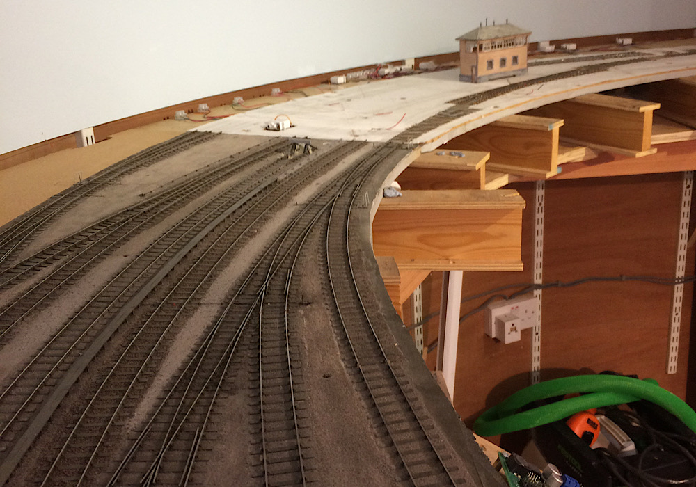 ......Edit now it’s loading! And here’s the north end again looking south this time with the overall roofing drunkenly perched on platform and mid air.... 2787_282345_320000000.jpg 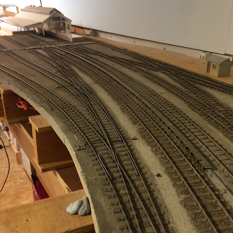 And lastly baseboard 5 looking at baseboard 4, the white one with no track, and then south to board no 3 with the Abbotsbury road bridge, another Rice model, hiding he junction beyond to Weymouth and Yeovil Town. 2787_280144_470000000.jpg 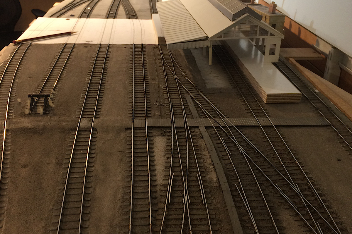 Kind regards Andrew Edit. I tried uploading a better version of this photo and it seems to have mucked it up. So here’s the original again....! 2787_282353_450000000.jpg 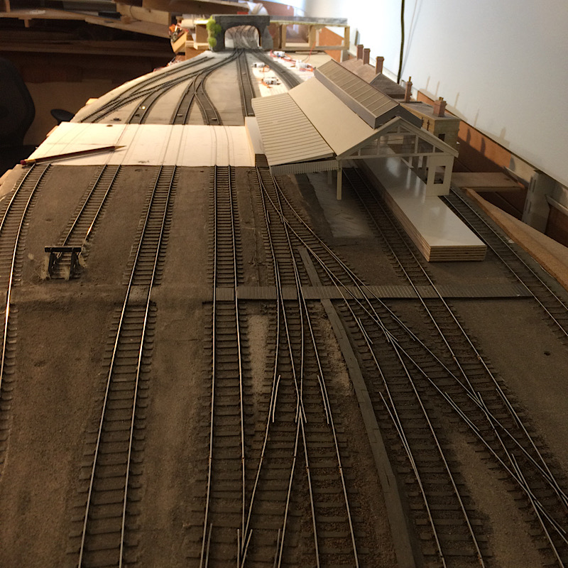 |
||
| Last edited on 29 Jan 2020 04:54 by Andrew Duncan |
|||
|
posted: 27 Jan 2020 01:10 from: Rob Manchester
click the date to link to this post click member name to view archived images |
Hello Andrew, Happy New Year to you too Rob |
||
|
posted: 27 Jan 2020 01:23 from: Martin Wynne
click the date to link to this post click member name to view archived images |
Hi Andrew, Looking good. It's great to see some pictures of the new layout coming along. Thanks for posting them. cheers, Martin. |
||
|
posted: 27 Jan 2020 22:26 from: Andrew Duncan
click the date to link to this post click member name to view archived images |
Rob Manchester wrote: Hello Andrew,Hello Rob Yes thanks for the encouragement and yes it does feel good to see all assembled, a case of the sum of the parts being more....! Kind regards Andrew |
||
|
posted: 27 Jan 2020 22:28 from: Andrew Duncan
click the date to link to this post click member name to view archived images |
Martin Wynne wrote: Hi Andrew,Hello Martin Very good to hear from you and thanks for the compliment. Kind regards Andrew |
||
|
posted: 8 Feb 2020 23:25 from: Andrew Duncan
click the date to link to this post click member name to view archived images |
Hello everyone A bit of progress today. I’ve cut and temporarily installed track on board 4 which is all of 10” wide and about 18” deep from front to back. Wired the track ( three districts Up Main, Down Main, and Marshalling yard) and am about 50% of the way through wiring and installing the 6 pole DIN plug and socket to feed just track power to this board. No point work on this board so no servo power or data cables, which makes it a very simple job. I was going to upload a picture or two but they seem to have disappeared...? I’ll investigate and upload them tomorrow all being well.. Kind regards Andrew |
||
|
posted: 15 Mar 2020 16:59 from: Andrew Duncan
click the date to link to this post click member name to view archived images |
Hello everyone I’ve been wondering how much difference it would make to the feel of the Yeovil if I got the two platforms in place. And I think that this was spurred on by a couple of encouraging comments about it starting to look like a railway (Rob)and the possibilities that this opened up(John). So platform construction time it is and the two pictures below give an idea of how far I’ve got. Visually the big difference is both the presence of platforms (!) and the covering of the surface mounted servos. Because of needing access to the servos, the platforms needed to be removable and as they both cross three baseboard joints I wanted to make them as one so that no joins show in the platform surface. With my old Yeovil layout ( in 00) everything was surface mounted and the scenery all demountable in the Rice jigsaw manner. And this layout will be the same in the station area at least. This photo shows the up platform before I surfaced it. It’s all made with 2mm MDF framing and slightly strangely 1.3mm MDF for the surface. I think I’ll probably surface that with a decant cartridge paper. 2787_151151_250000000.jpg 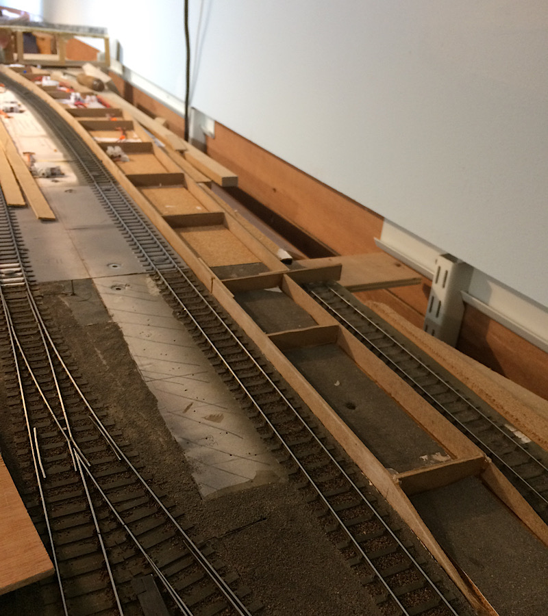 And This photo shows the previous platform and station forecourt surfaced with 1.3mm MDF. And platform two awaiting its surface. I’d better get back to doing that ! 2787_151154_570000000.jpg 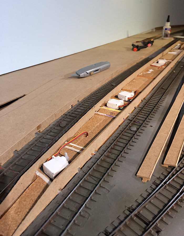 Kind regards Andrew Edited for numerous spelling mistakes ! |
||
| Last edited on 15 Mar 2020 23:26 by Andrew Duncan |
|||
|
posted: 15 Mar 2020 20:10 from: Rob Manchester
click the date to link to this post click member name to view archived images |
Hi Andrew, Looking good, glad somebody takes notice of my comments Hiope you are surviving the supermarket chaos and the lack of decent goverment action in the current national crisis........ Rob |
||
|
posted: 15 Mar 2020 23:31 from: Andrew Duncan
click the date to link to this post click member name to view archived images |
Hello Rob 1 always! 2 I’ll tell you in two or three months time! Andrew |
||
|
posted: 29 Mar 2020 16:19 from: Andrew Duncan
click the date to link to this post click member name to view archived images |
Hello everyone A bit of platform and scenic progress that represents three or four days work that in the normal run of things I’d never normally have were it not for the Coronavirus. So with our bricks and mortar shops closed and just the website operational and social distancing in force all my usual “ excuses “ for not getting something done on Yeovil have largely evaporated. So here are four or five pictures showing the jigsaw scenery approach I’m taking working from the back of the layout, station forecourt area , forward towards the front. This photo is just the plain track only with servos surface mounted. 2787_291040_590000000.jpg 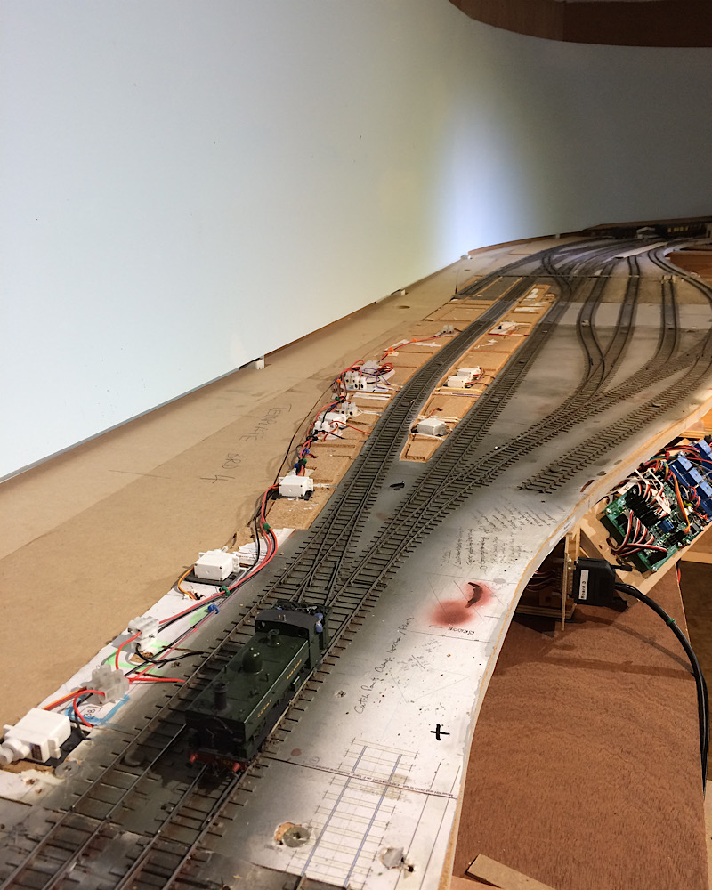 This shows half of the length of platform 1 with the slightly higher ground behind of the road coming down to the station forecourt and the embankment of the road that crosses the station via a stone built bridge. 2787_291039_090000000.jpg 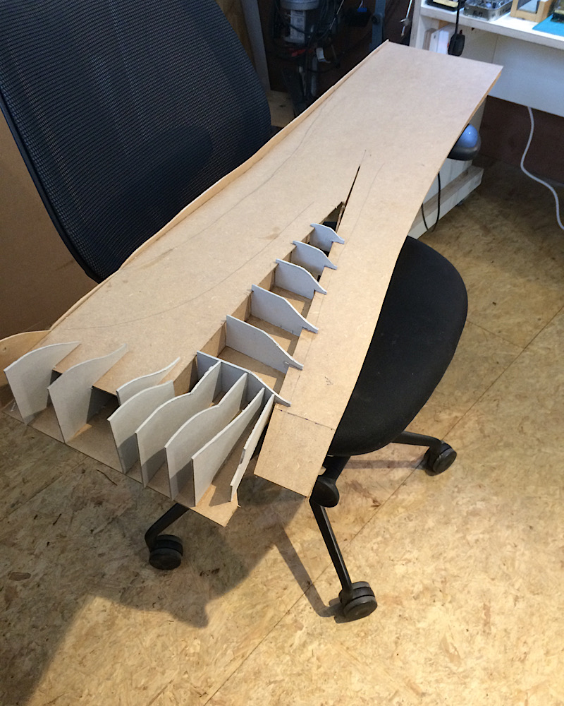 This shows that jigsaw section in place on the layout and the next jigsaw piece along which comprises the other end of platform 1 the bay and the road entrance to the goods yard. You can also see platform 2 in place along with the station building ( from Yeovil mk1) and the overall roof(ditto), oh and the road bridge also from the original Yeovil. 2787_291036_070000000.jpg 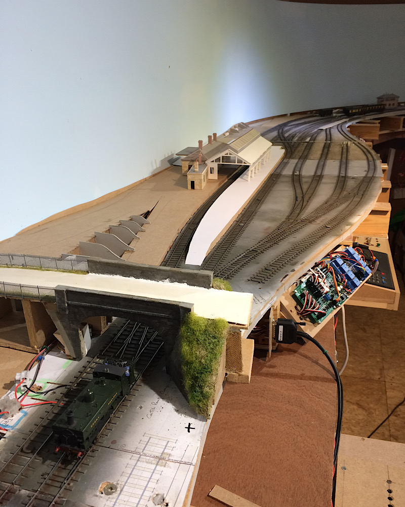 And lastly a view taken from the opposite direction with one of my favourite locos a buffalo with a couple of Triang clerestory coaches and a D&S parcel van which was the first brass coach kit I ever made. Went together surprisingly easily, very well designed. Ha I’ve just looked again and realised it’s hidden by the roof. 2787_291032_440000000.jpg 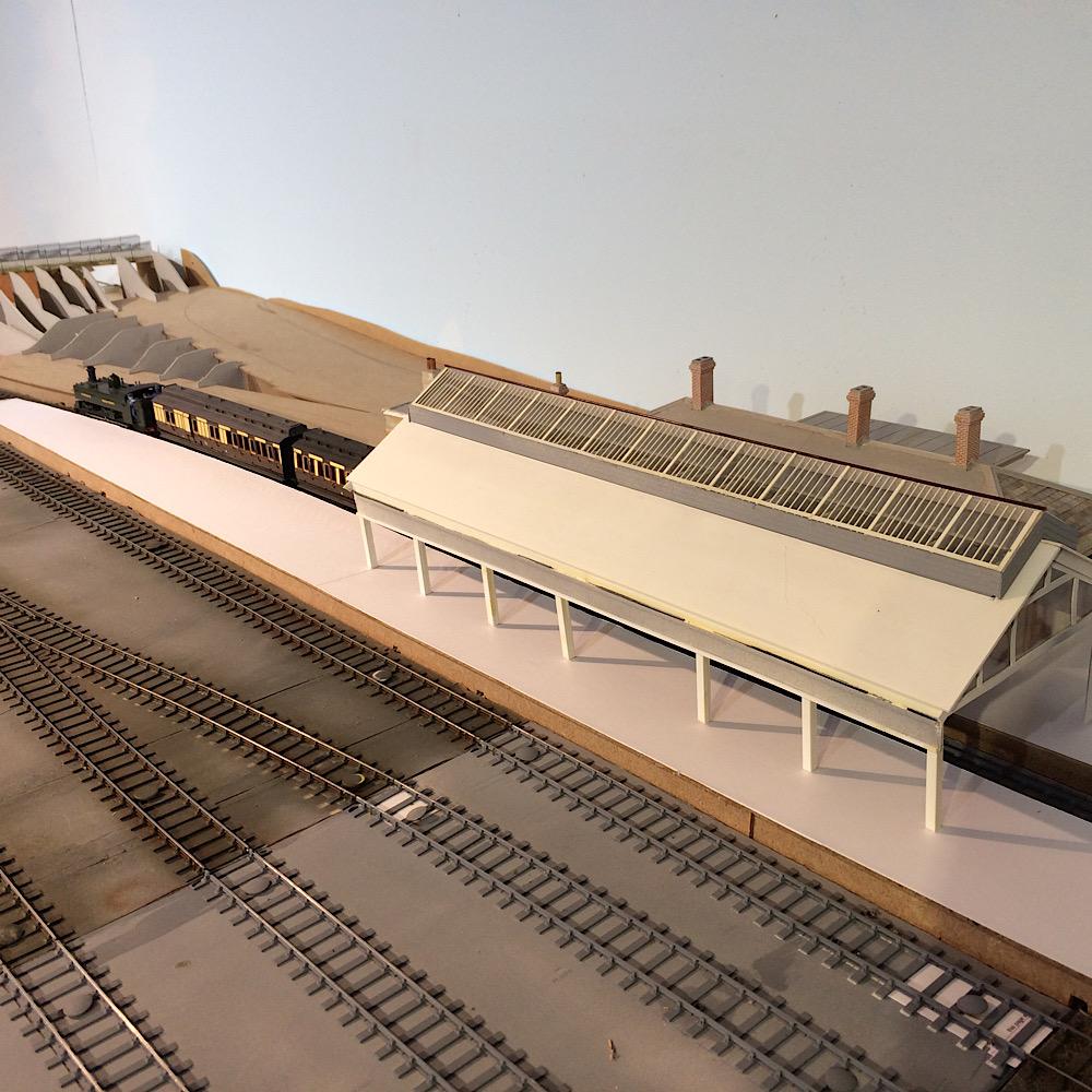 Kind regards Andrew |
||
| Last edited on 29 Mar 2020 16:24 by Andrew Duncan |
|||
|
posted: 29 Mar 2020 17:21 from: Hayfield
click the date to link to this post click member name to view archived images |
Andrew Looking very impressive John |
||
|
posted: 29 Mar 2020 18:16 from: Tony W
click the date to link to this post click member name to view archived images |
Hi Andrew. Amazing how much difference a small amount of scenery makes to the appearance. Keep up the good work. Regards Tony. |
||
|
posted: 29 Mar 2020 19:22 from: Phil O
click the date to link to this post click member name to view archived images |
Hi Andrew, I have to agree with the others, a few buildings and a bit of scenery makes a huge difference. Great work. Cheers Phil. |
||
|
posted: 29 Mar 2020 21:15 from: Andrew Duncan
click the date to link to this post click member name to view archived images |
Chaps Thanks for the compliments and encouragement. All very much appreciated and yes your right Tony the addition of a little realism makes a big difference, sets the scene to some extent and encourages me on. I’ve been reading Gordon S,s Eastwood Town chronicles of late and noticed how he builds to quite a high level of detail track and environs in his approach and this was partially why I found myself putting in the platforms just to start with and then realising that I might as well make them integral with the forecourt and the embankments behind. I suddenly feel I’m building a model of a railway running through he landscape rather than just forever building turnouts! Nice feeling! Andrew |
||
|
posted: 30 Mar 2020 09:55 from: Phil O
click the date to link to this post click member name to view archived images |
I think the real fun begins once the track is laid and tested. Getting onto the scenics is a huge step forward once the basics are properly done. Cheers Phil |
||
|
posted: 31 Mar 2020 23:07 from: Andrew Duncan
click the date to link to this post click member name to view archived images |
Phil O wrote: I think the real fun begins once the track is laid and tested....Yes well I'm not sure I've got there yet Phil but thanks for the encouragement. I'm currently working on the basic plug in scenery sections (just the ones in front of the station area) in front of the trackwork that when in place will largely hide all the electrics and I hope give a real depth to the scene. Stop me staring at all those wires and holes between baseboards and shelf supports. Kind regards Andrew |
||
|
posted: 5 Apr 2020 18:40 from: Andrew Duncan
click the date to link to this post click member name to view archived images |
This landscaping lark is getting quite catching! I’ve been spending my unexpected free time on constructing the foreground from the north end ( far right hand end) of the station working my way south (left therefore) through the station marshalling yard in front of the platforms to the road over bridge and then on to the cattle pens the other side of the bridge. There are three sections of plug in scenery so made which stretch across the joins of 4 baseboards. I’ve tried to avoid lining up baseboard joins and scenery sections so as to reduce the impact of the straight seismic cracks in the ground. This is one of the real benefits of jigsaw scenery in that it uses( or tries to use) natural breaks , curved lines, embankments, hedges, changes in surface texture to stop the eye being drawn to the joins and the multiple imperfections! The far north section on a tight curve upside down during construction 2787_051325_200000000.jpg 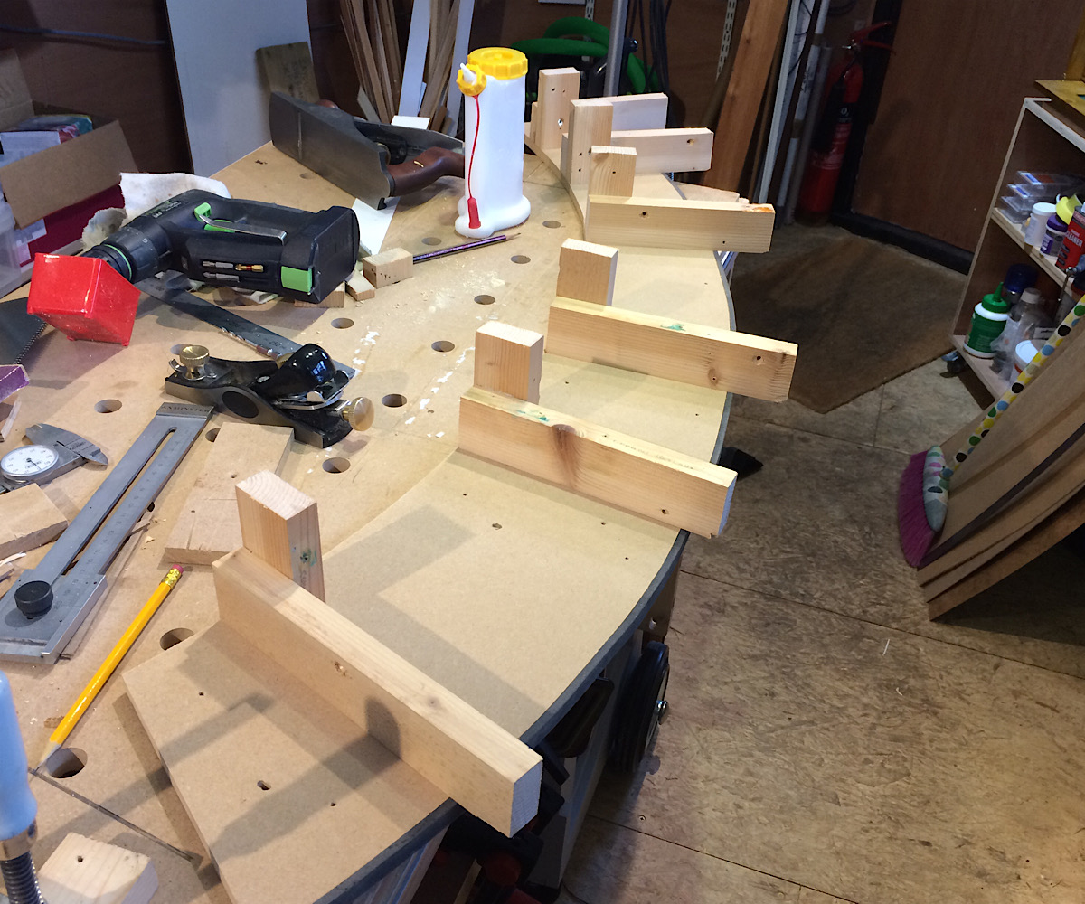 The same bit, right way up and ready to plug into place but at this stage without its side skirt! 2787_051326_100000000.jpg 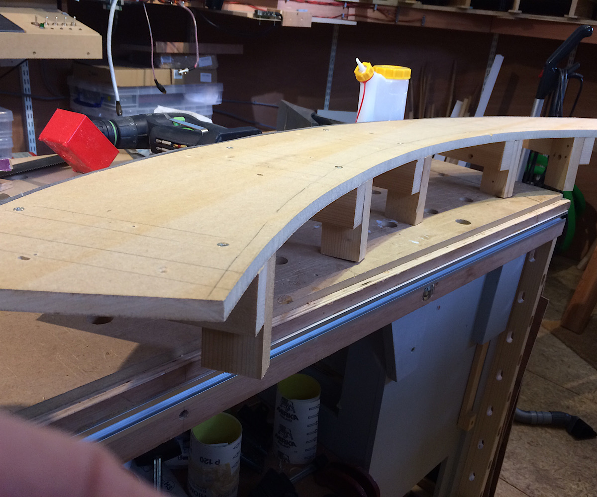 Skirt installed and plugged in place 2787_051326_520000000.jpg 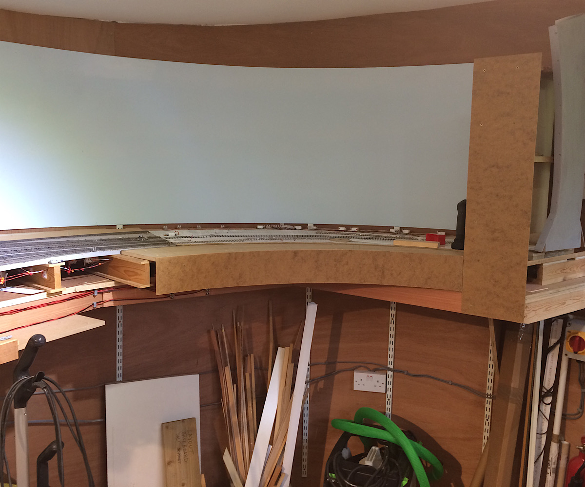 Two further sections moving south through the station with cork surface in place and in the join some rubber underlay to help the two sections meet without cracks,....we’ll sort of. Makes up for my rather hit and miss wood work. 2787_051327_580000000.jpg 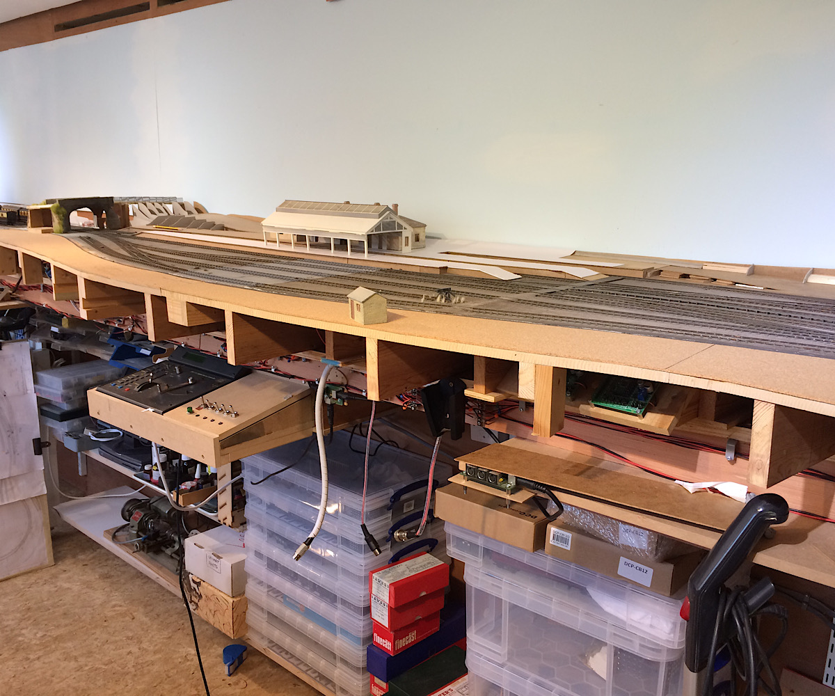 Skirt clamped in place prior to cutting to length. Makes a big difference to the look and feel of the station area 2787_051328_520000000.jpg 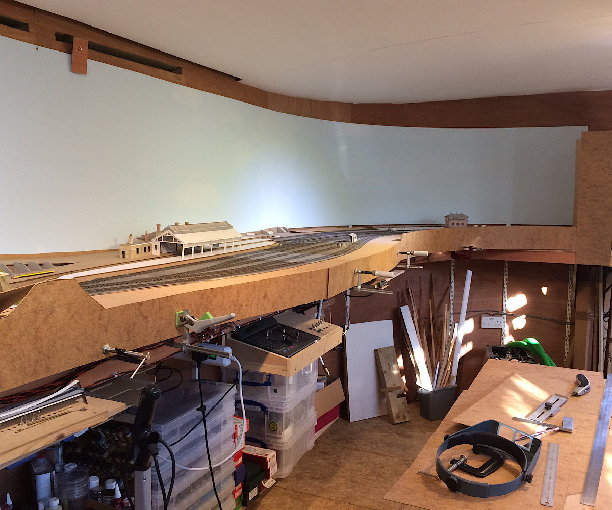 A view from the road bridge looking north over the station. 2787_051329_480000000.jpg 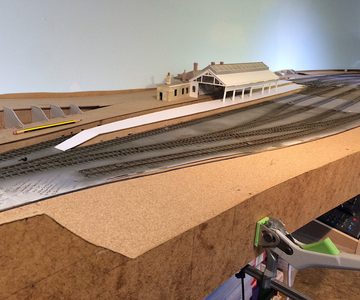 |
||
| Last edited on 7 Apr 2020 21:03 by Andrew Duncan |
|||
|
posted: 5 Apr 2020 20:52 from: Phil O
click the date to link to this post click member name to view archived images |
Looks good, can't wait to see a Weymouth boat train hammering through. | ||
|
posted: 5 Apr 2020 21:13 from: Rob Manchester
click the date to link to this post click member name to view archived images |
Andrew, Great stuff, looks brilliant. Keep the updates rolling and keep safe. Rob P.S. What is the bottle-type item at the top of the first pic ? Get the feeling it is probably something obvious... |
||
|
posted: 5 Apr 2020 22:28 from: Andrew Duncan
click the date to link to this post click member name to view archived images |
Rob Manchester wrote: Andrew,Hello Rob Thanks for the encouragement....always welcome It a really clever glue bottle that charges itself and squirts glue out without tipping it upside down. I got it from Rutlands tools along with a small version as well. Really good product! Kind regards and you look after yourself as well. Andrew |
||
|
posted: 5 Apr 2020 22:43 from: Andrew Duncan
click the date to link to this post click member name to view archived images |
Phil O wrote: Looks good, can't wait to see a Weymouth boat train hammering through.Hello Phil Thanks and yes me as well, although hammering might be an exaggeration as I think the speed limit through the station was 25 mph but I might just turn the wick up from time to time, just for the fun of it you understand.... Kind regards Andrew |
||
|
posted: 6 Apr 2020 21:00 from: Rob Manchester
click the date to link to this post click member name to view archived images |
Andrew Duncan wrote: Rob Manchester wrote:Andrew,Hello Rob Hi Andrew, Thanks for the glue bottle info - I see them on Rutlands site although they are out of stock. Clever idea. Looking at your pictures again I spotted the trusty Unimat lathe ( DB or SL ? ) and the pile of kits under the bench so you will have some projects to work on in the next few months..... Rob |
||
|
posted: 6 Apr 2020 22:14 from: Tony W
click the date to link to this post click member name to view archived images |
Hi Andrew. Your design concept is now apparent and the result is quite stunning in my view. The baseboards for my layout will feature detachable scenery but the design is merely theory at present, so I shall be watching yours develop with keen interest. Regards Tony. |
||
|
posted: 7 Apr 2020 20:34 from: Andrew Duncan
click the date to link to this post click member name to view archived images |
Rob Manchester Hello RobHi Andrew,Thanks for the glue bottle info - I see them on Rutlands site although they are out of stock. Clever idea. Looking at your pictures again I spotted the trusty Unimat lathe ( DB or SL ? ) and the pile of kits under the bench so you will have some projects to work on in the next few months..... I'm afraid I don't recall which model the lathe is, but what made me chuckle is your comment about the pile of kits. That pile are empty boxes from kits that I have built! You should see the shelves on the other side of the shed. Filled with kits that I haven't built, makes the pile in the photo look minuscule! This is why I need to get this layout finished so I can start to build some of the vast quantities of stock to run on it! Glad you found the glue bottle OK, well worth spending your money on when they come back into stock. Kind regards Andrew |
||
|
posted: 7 Apr 2020 20:59 from: Andrew Duncan
click the date to link to this post click member name to view archived images |
Tony W wrote: Hi Andrew.Hello Tony Well thank you very much indeed, stunning? I don't think anything I've done in my railway life, let alone the rest of my life, has ever been referred to as stunning so I take it as a great compliment and all the more so, coming as it does from such an accomplished model maker. I was looking at your latest stuff on Brimsdown over on your Scaleforum thread a day or two ago and rather envying (in the best possible sense) your minute attention to detail both in the really beautiful quality of your track work above board and the detail of your bit about the wiring below. You are also a natural teacher in your approach and there aren't many of you around so please keep up the excellent work. Back to Jigsaw scenery for a moment. I'm sure you're aware that the idea is not a new one and that Iain Rice was I believe the first person to promote the approach. Indeed it was he who helped me (or more accurately half built !) my first attempt at Maiden Newton and Yeovil PM and like you, he is a very good teacher. So credit must go to him for the idea I believe. I do however take your generous compliment on my rendering of it. Thanks again you've made my day! Andrew |
||
|
posted: 11 Apr 2020 04:38 from: Andrew Duncan
click the date to link to this post click member name to view archived images |
A bit more progress on the scenics side this week. This photo shows the 4th plug in section just south of the Sherborne road bridge plugged in but before recieving it’s side skirt. You can see the cattle dock put roughly in place there which will be built into a jigsaw section of scenery that will include the embankment it sits in and the service road up to the Sherborne road that’s just crossed the station throat 2787_102253_130000000.jpg 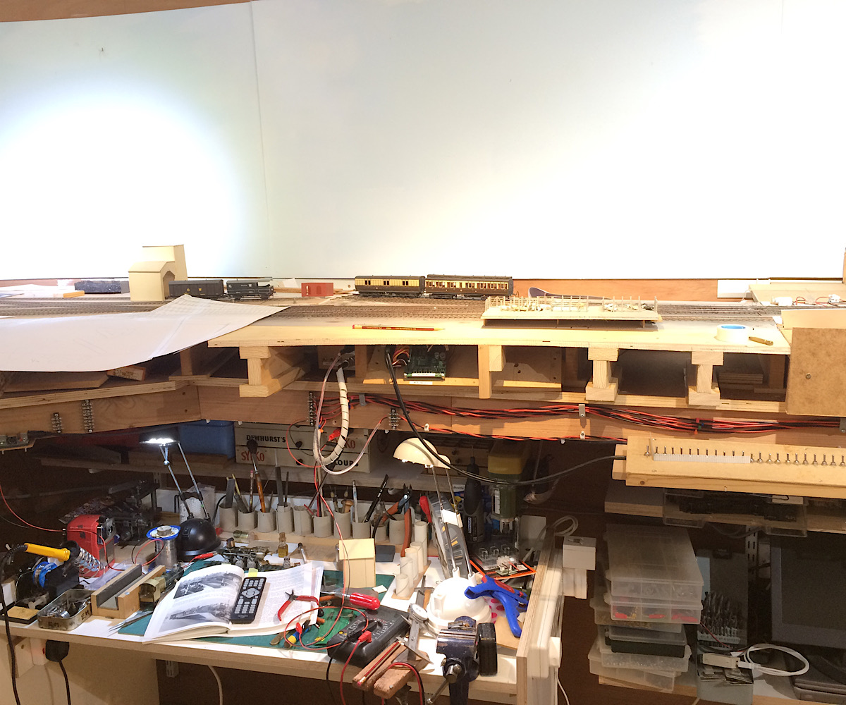 Here is the view again looking from the north across the cattle dock to the MPD. It’s now grown a side skirt shaped for the embankment and them main Sherborne road and the service road. 2787_102254_090000000.jpg 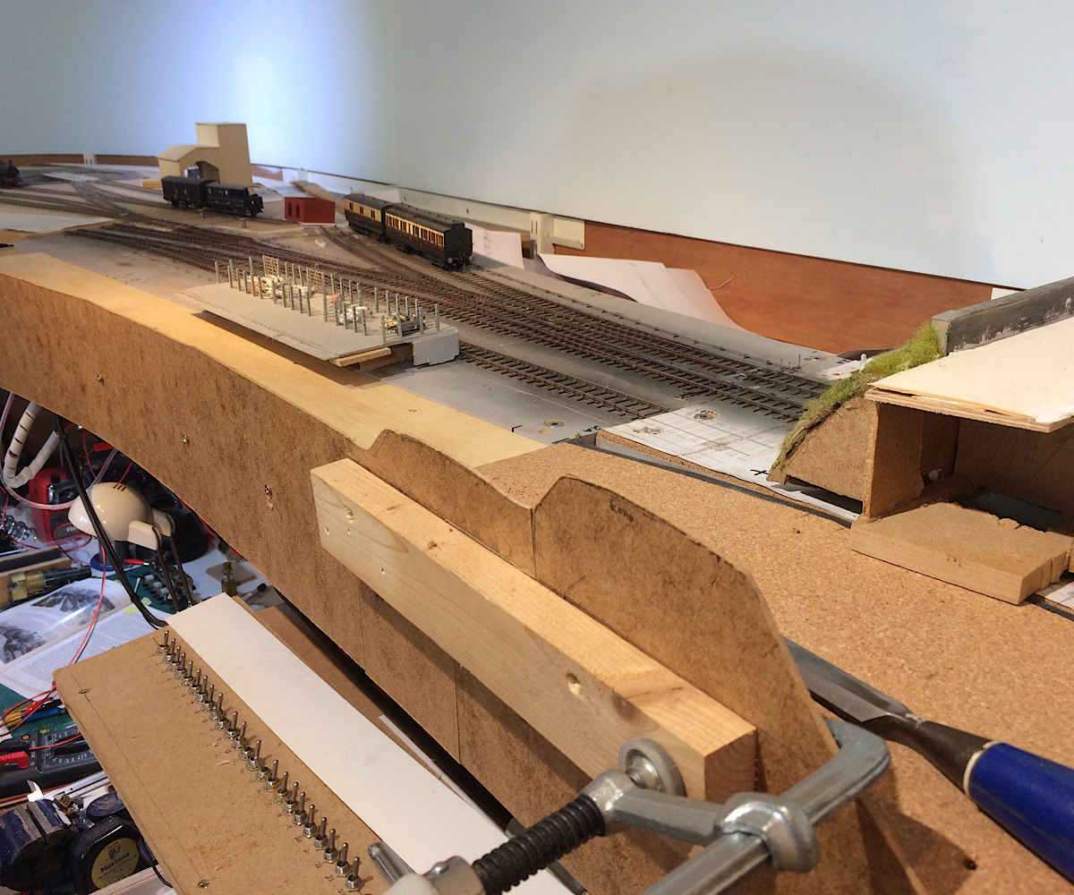 And here a bit of progress withe first of the formers in place for the service road down the the cattle dock 2787_102257_590000000.jpg 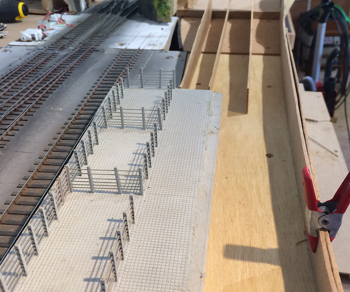 And here a couple more. I’d decided by this time the whole of this section,which crosses a baseboard join, should be a separate lift out section rather like platform 1 the scenery behind platform 1 that I did last week. By this time I’d also added in an extended base for the Sherborne road bridge as I needed that as reference point off which to build this whole lift out bit. I’m afraid though that it a bit difficult to see in this picture. 2787_102259_070000000.jpg 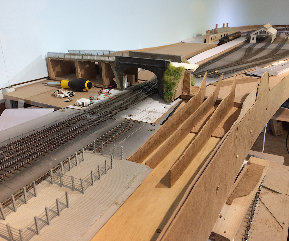 And here is the service road base and part of the road embankment built ready to receive the road surface that goes up to the main road. The cattle dock incidentally is made from a Ratio kit which is modelled on the Yeovil Pen Mill one and is the one I made originally for Yeovil Mk1. It’s a small world. When I’ve got the main structure finished I’ll take a photo of the whole thing so you can it in all its glory! Best wishes and a happy if rather confined Easter! Andrew 2787_102259_520000000.jpg 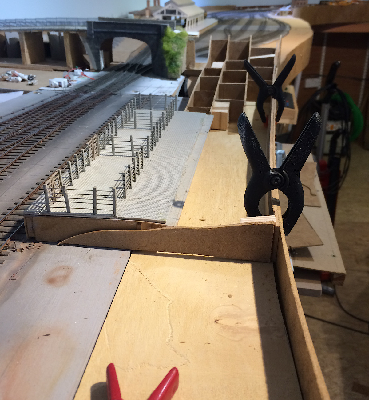 |
||
| Last edited on 11 Apr 2020 04:47 by Andrew Duncan |
|||
|
posted: 11 Apr 2020 21:58 from: Rob Manchester
click the date to link to this post click member name to view archived images |
Hello Andrew, Sterling work as usual, my afternoon activities consisted of some garden tidying and trashing some back issues of railway magazines ( that means going through and tearing out the bits I think may be of future interest Today's random thought concerns the cattle breeds on your layout. Have you checked this out - you may need to respray (some) of the black and white ones Take care and Happy Easter to you and family. Rob |
||
|
posted: 11 Apr 2020 23:33 from: Andrew Duncan
click the date to link to this post click member name to view archived images |
Rob Manchester wrote: Hello Andrew, Hello Rob Thanks for the compliment. Having a good clear out is very good for the soul I think. We don’t it often enough but when we do, or I do, then I usually get some reaL satisfaction out of it. Something along the lines of breaking the unspoken truism that things tend to own us and not tother way round. And it creates space which sometimes remains empty for while, this despite Nigel's chaos theory. When I ditched all my Railway Modellers going back to the mid late sixties a few years ago I felt quite brave and adventurous almost. And in fact the same when I ditched Yeovil Mk1 and Maiden Newton. They’d had their day perhaps? So well done, very tempting to cling on to nostalgia. As to cattle breeds, you make an interesting and hitherto unthought of (well I hadn’t thought about it) point. Is this something that you know something about by any chance? Incidentally talking of cattle heres the jigsaw piece with the cattle dock built into it, both in it place and then with it lifted out to show the area that it’s a part of. So far seems to worked out quite well, always a bit of a surprise but as I gain more experience I generally tend to get better at making stuff. Ok time to go and get some kip. Take care happy Easter to you and your wife,,,what’s her name ? Kind regards Andrew 2787_111823_160000000.jpg 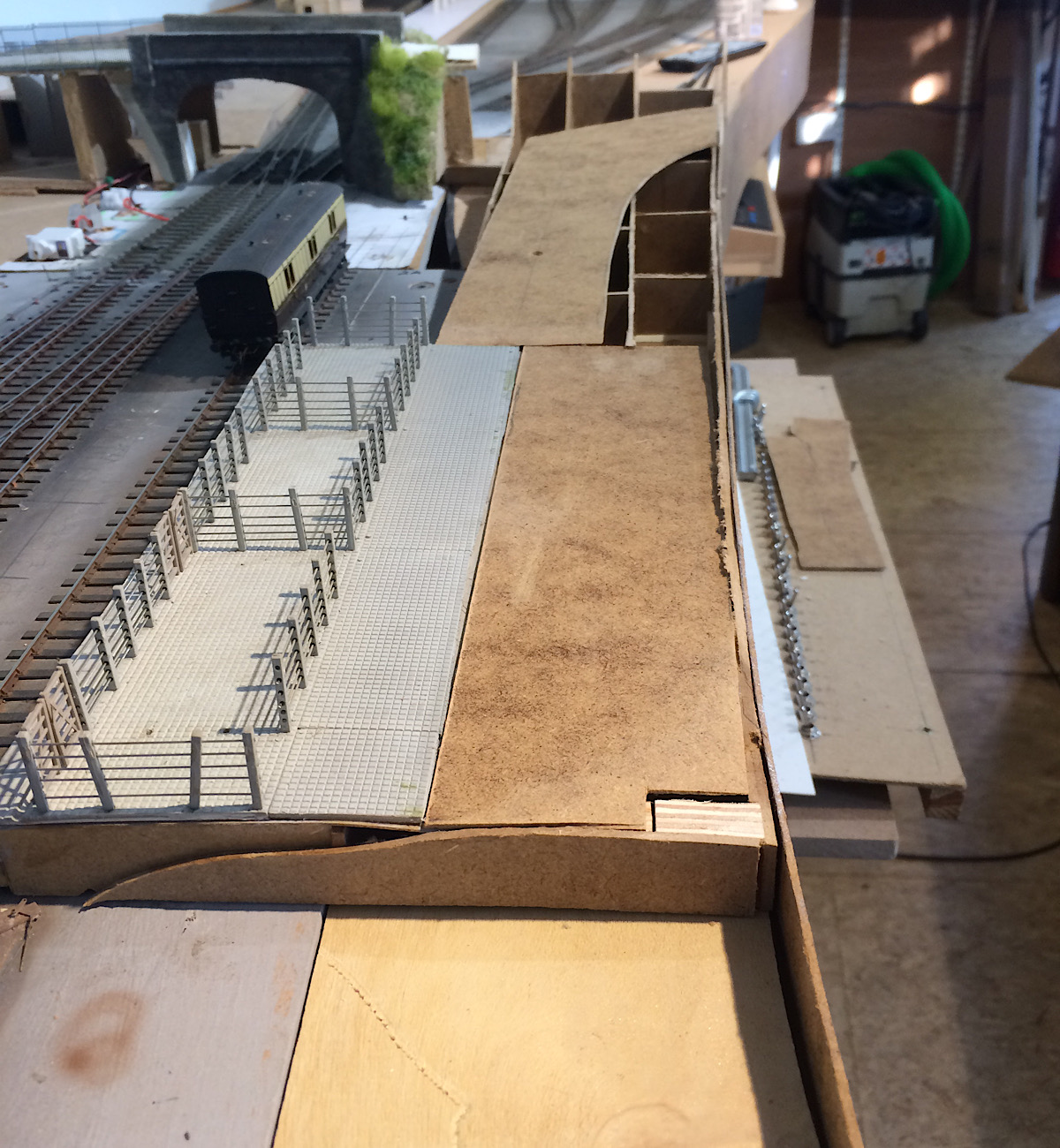 2787_111824_100000000.jpg 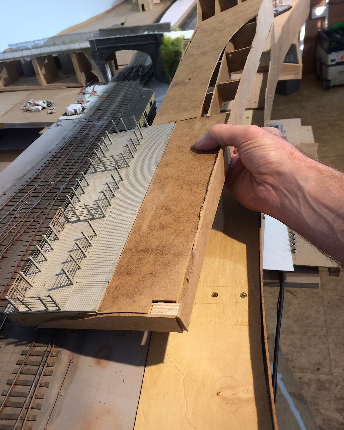 |
||
|
posted: 12 Apr 2020 00:05 from: Rob Manchester
click the date to link to this post click member name to view archived images |
Hi Andrew, She is Jane No I am not an expert on cattle ( although if my mum's parents hadn't divorced leading to my mum moving to Manchester I could have been raised on a farm )but I do know that in them olden days cows were not black and white A quick 'Google' found this page - the last bit of the fourth paragraph may date the black and white cows. I am surprised that MRJ hasn't done an article on the subject. Your 1:76 cows by the bridge sure look a bit sick - thanks for the extra photo. Do I spot a Festool dust machine on the floor ? - must keep my eyes on the train bits.... Regards Rob |
||
|
posted: 12 Apr 2020 15:36 from: Stephen Freeman
click the date to link to this post click member name to view archived images |
I rather thought that MRJ had done something on cows. | ||
|
posted: 12 Apr 2020 21:50 from: Rob Manchester
click the date to link to this post click member name to view archived images |
I have searhced the MRJ index here using the words cow, cattle, farm, animals etc but nothing comes up - must admit I had a vague memory of something being written. Maybe it was a part of a cattle wagon article of similar. Rob |
||
|
posted: 13 Apr 2020 09:28 from: KeithArmes
click the date to link to this post click member name to view archived images |
Try MRJ 10. Article by Tim Watson. Sorry, I can't check it as a lot of my early MRJs were damaged by water. Keith |
||
|
posted: 13 Apr 2020 21:53 from: Rob Manchester
click the date to link to this post click member name to view archived images |
Hi Keith, Thanks for the article location but it is just about crop farming rather than cows. Interesting read though Reading some web pages and forums seems to give the impression that black and white cows were not common until the beginning of the 1950's even though the UK Society for them had been around for 40 years and the first imports from Holland and Northern Germany had taken place in the 19th century. For old times sake I personally would populate the fields ( or cattle vans/pens ) with traditional British breeds for a steam era layout based in the 1950's or earlier. Time to get the airbrush to work on those of yours Andrew Rob |
||
|
posted: 13 Apr 2020 23:28 from: Andrew Duncan
click the date to link to this post click member name to view archived images |
Rob Manchester wrote: Hi Andrew,Hello Rob Please tell Jane that I’m sorry to hear about her plight, not being able to go out, meet friends, drink coffee and eat cake is punishment indeed. I suppose that it would be considered insensitive or bad form to suggest she starts soldering bit of brass or building your layout for you wouldn’t it......? Yes well it was just an idea, you’ve always got single malts and scrabble to fall back on haven’t you. Thanks for the Holstein link. Appears your grandparents lacked forethought in some areas which is a shame but it looks as though I’d be pretty safe spraying them a sort of reddy brown colour perhaps? As to whether I should calling out the vet, I suspect that with little wash and brush up and coat of new paint they will be right as rain. And the Festool, yes you spotted correctly. Connected up to a circular saw or a sander hardly a speck of dust escapes into the atmosphere. Quite magic really. Kind regards Andrew Edit. Sorry Rob missed your later posting. Will reply tomorrow |
||
| Last edited on 13 Apr 2020 23:33 by Andrew Duncan |
|||
|
posted: 13 Apr 2020 23:44 from: Rob Manchester
click the date to link to this post click member name to view archived images |
Hi Andrew, Hmm, maybe I will try and get Jane into tree making or set her practising with the static grass gizmo, she is better than me at creative things. She makes greetings cards for a hobby and the results are pretty good. Think letting her loose with my resistance soldering unit may be a step too far though..... Ah Festool, the white van mans favorite tool brand ( with respect to Dewalt who think they are ). Anybody with a TS55 track saw must be good at his job Have you got all the Model Railway Journals ? The article Keith mentioned is interesting. Remind me - are you aiming at a particular year for the layout ? Rob |
||
|
posted: 14 Apr 2020 09:10 from: Andrew Duncan
click the date to link to this post click member name to view archived images |
Rob Manchester wrote: Hi Andrew, Rob What a responsible and creative husband you are. Looks like Jane may have her plate so full, that in time she’ll look back on her bored days with some nostalgia ...? As to tools of choice, yes the TS 55 is an excellent tool when combined with rails and the Hoover, straight beautifully smooth cuts with little breakout and little mess, I love it. It’s odd that you should mention the Ryobi One+ though as I bought their hedge trimmer last year and was pretty impressed by it's power and ease of use, I’d never had one before and suddenly found shaping of a couple of Box bushes and a juniper(eras?) was a doddle. If they do a strimmer using the same system that’ll be the next one I have my eye on. And lastly yes I think I do have no 10 MRJ, so I’ll take a look. As to what type of wheat, well I have to admit to failing once again....hadn’t even thought about it. Call myself a railway modeller...maybe that long ago (oh yes the year is 1922) it would have been Spelt ? I’m not sure and at 4mm to the foot would I be able to tell..... Here’s a shot of my experiments yesterday, testing hill height. I think it maybe a bit too dominant, especially so for the back of the layout. Thanks again for your interest, feedback and humour. Kind regards to you both Andrew 2787_140407_170000000.jpg 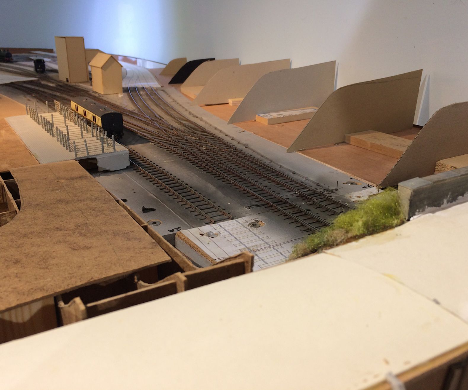 |
||
|
posted: 14 Apr 2020 11:13 from: Martin Wynne
click the date to link to this post click member name to view archived images |
Andrew Duncan wrote:Here’s a shot of my experiments yesterday, testing hill height. I think it maybe a bit too dominant, especially so for the back of the layout.Hello Andrew, Is that a railway cutting behind the tracks? It's difficult to see the exact angle from the photo, but it may be a bit steep. A typical railway cutting or embankment (it varies with the type of soil and drainage) would be angled at about 1.5 to 1, i.e. 1.5 horizontal to 1 vertical (about 33 degrees from the horizontal). Anything steeper risks a landslip onto the line in wet weather. On many model railways there simply isn't space for that, so something steeper has to suffice. Or a small retaining wall is added along the bottom of the slope. In areas where the soil is wet clay, the angle will be much flatter, up to about 4 to 1 in some cases. Sufficient land for the cutting slope would have been purchased by the railway company, so the boundary fence would normally run along the top of the slope. On the other hand the railway may have been built onto the natural hillside, in which case no such calculations are needed, but in that case the slope and top level would likely be more uneven than you have on the formers in your photos. And the boundary fence will then be at the bottom of the slope. Earthworks are one area where railway company and period don't apply on the prototype. HS2 will be using the same rules as Brunel. Thanks for the updates, it's starting to look very good. cheers, Martin. |
||
|
posted: 14 Apr 2020 11:46 from: Hayfield
click the date to link to this post click member name to view archived images |
Martin Whilst I have not learnt to doubt your figures, I think I am misunderstanding your reply. As a child I watched the West Coast Mainline above the southern end of Bushey (& Oxhey) station from the embankment high above whilst my dad attended his allotment. From memory The drop down to the tracks must have been on the south side 45% if not greater, on the north side (behind Kingsfield Road houses it seemed much steeper I have found a photo showing the North side and it shows how wrong memories can be http://www.ebay.co.uk/itm/Bushey-Oxhey-Railway-Station-Postcard-Hatch-End-Watford-Harrow-Line-4-/252581686564 My view point was much further along, you can see the start of the embankment on the left which was behind the coal yard, it gradually rose in height to the water tower for the troughs and Oxhey Road bridge. As a youngster it was quite a thrill to slightly decent what was quite a steep embankment, though not quite as severe as remembered |
||
|
posted: 14 Apr 2020 12:51 from: Martin Wynne
click the date to link to this post click member name to view archived images |
Hayfield wrote: As a child I watched the West Coast Mainline above the southern end of Bushey (& Oxhey) station from the embankment high above whilst my dad attended his allotment. From memory The drop down to the tracks must have been on the south side 45% if not greaterHi John, Can you remember what sort of soil your dad was digging on his allotment? If it was well-drained sandy/gravelly soil, the angle may have been up to 1:1 (45 degrees), but it wouldn't have been steeper than that unless the cutting was through solid rock or very rocky terrain. Also, if the foot of the slope is set well back from the running lines, perhaps for a yard or sidings, a steeper slope might be used where the risk of a landslip reaching onto the running lines is less likely. Obviously in areas of high land values the railway company wouldn't want to purchase more land than necessary. Nowadays there are various methods used to stabilise slopes allowing them to be steeper. cheers, Martin. |
||
|
posted: 14 Apr 2020 13:46 from: Hayfield
click the date to link to this post click member name to view archived images |
Martin I think the top soil on the allotments was fine, going North after the station there are two brick built viaducts built from local black clay which was certainly evident in Oxhey Village (which was called New Bushey in the early 1900's). I think the house I was born in was initially built to house the railway builders and there were several old brick works locally http://www.facebook.com/OxheyVillage/photos/a.425572759312/10156383781069313/?type=1&theater Lovely shot of the station forecourt, Where the station sign was there was an evening paper seller selling both the Evening Standard and Evening News, I used to buy papers from him and deliver them to local houses after school Going back to the first photo I stood about 100yds north of the water tower, which looks quite close in the photo as does the bridge but in fact quite a distance away |
||
|
posted: 14 Apr 2020 19:49 from: Andrew Duncan
click the date to link to this post click member name to view archived images |
Martin Wynne wrote: Andrew Duncan wrote:Hello MartinHere’s a shot of my experiments yesterday, testing hill height. I think it maybe a bit too dominant, especially so for the back of the layout.Hello Andrew, Thanks for your your thoughts on my slopes. I’ve modified them both in angle which is now closer to your recommendations and I e reduced them in height as well as I think that although the slope of the field behind does in fact go substantially higher, it’s probably much further away from the railway line that it does this. So this is what it looks like now. I may still take a smidgen or two off the height but I already think it looks a lots better both slope angle and height wise. I wonder if you can help me with the stair case that comes down from the bridge to rail level. I’ve not found any photos of it sufficient to tell at what sort of angle it’s likely to have followed. It must have been used by the shed staff and signal man. In the photo it’s represented by a grey card slope balanced precariously against the left hand side of the bridge. Is that about right do you think. The slope is 120 out and 80 high. Thanks again for your observations and help Kind regards Andrew 2787_141446_550000000.jpg 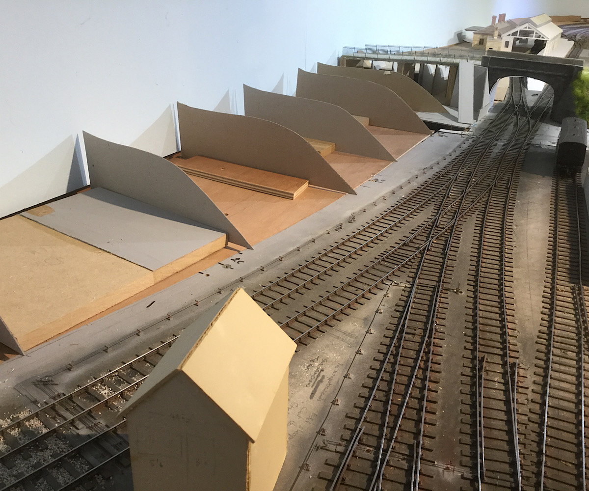 2787_141447_360000000.jpg 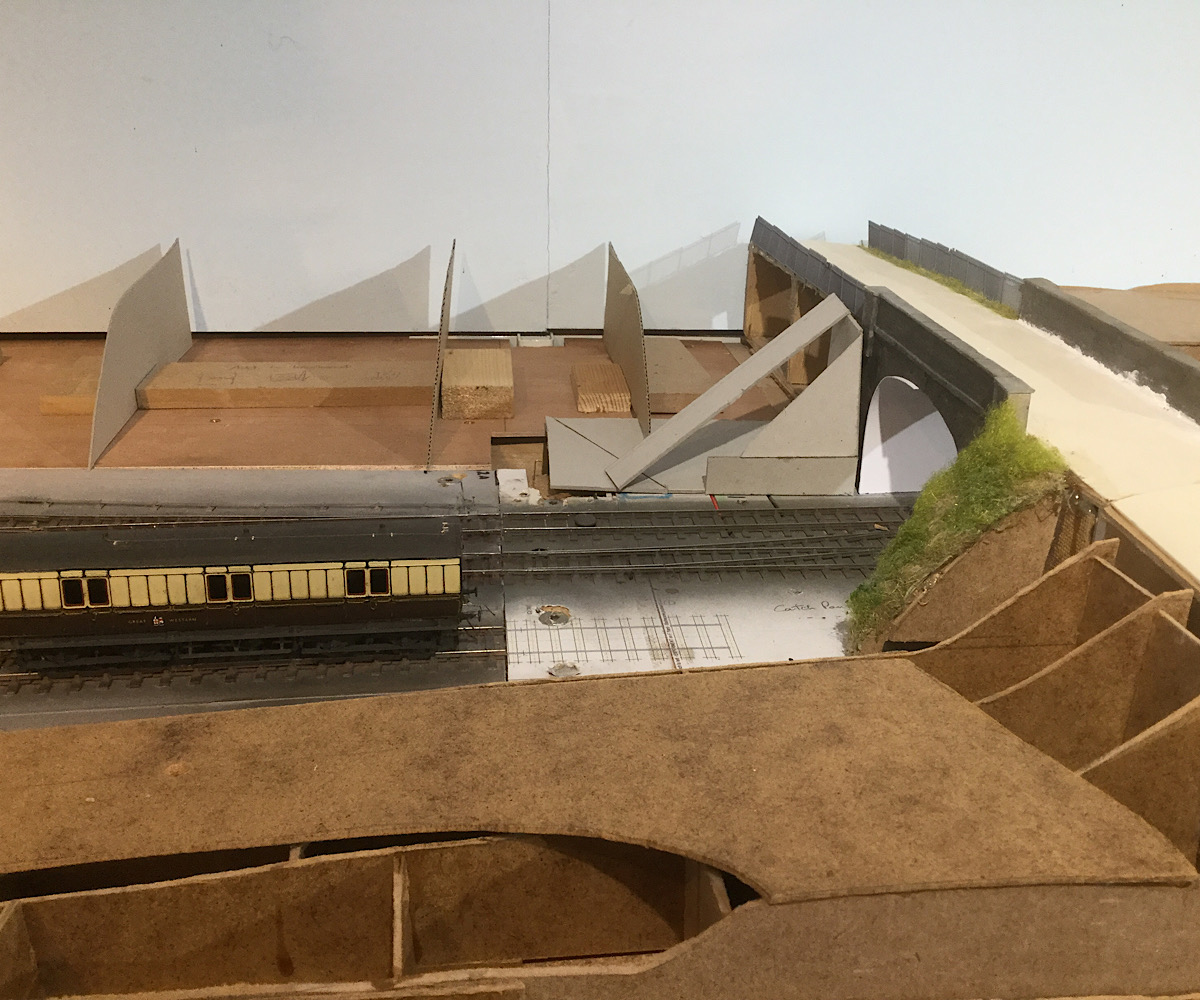 |
||
|
posted: 15 Apr 2020 00:18 from: Martin Wynne
click the date to link to this post click member name to view archived images |
Andrew Duncan wrote:I wonder if you can help me with the stair case that comes down from the bridge to rail level. I’ve not found any photos of it sufficient to tell at what sort of angle it’s likely to have followed. It must have been used by the shed staff and signal man. In the photo it’s represented by a grey card slope balanced precariously against the left hand side of the bridge. Is that about right do you think. The slope is 120 out and 80 high.Hello Andrew, That looks about right. For staff use only, rather than public, you could maybe go a bit steeper. I have dug out this drawing of LYR signal box steps. The notes say 45 degrees (10ft x 10ft), but it's not clear if that includes the top landing. Scaling the drawing the actual staircase part is a bit steeper at about 47 degrees from the horizontal: 2_141848_570000000.png  The notes there suggest a much easier angle of 24ft x 14ft for MR signal boxes. If it's down the side of an embankment it would need to match the angle of that of course, 1.5:1 as you have there, or whatever. It would need a fair-sized landing at the top, probably with a walled sideways offset to prevent members of the public falling down it. And it will need a handrail. cheers, Martin. |
||
|
posted: 15 Apr 2020 01:07 from: Rob Manchester
click the date to link to this post click member name to view archived images |
Hello Andrew, Looking at the first picture of the 'slope' I though it looked a little on the tall side but when viewed from the other direction it kind of looks correct, probably due to it's proximity to the bridge. Putting a ground surface between the formers you have constructed may make it appear different. What is your layout height from the floor ? Scenic features can look very different depending on the layout and operator's heights. My last fixed layout had a baseboard height of 63 inches although I may knock an inch or two off the next one - bring a soapbox if you ever visit Take care. Rob |
||
|
posted: 16 Apr 2020 00:00 from: Andrew Duncan
click the date to link to this post click member name to view archived images |
Martin Wynne wroteHello Andrew,Hello Martin Thanks for your general knowledge and research. The stairs follow a buttress that is approximately 45degrees (also I the photo) so maybe I should go a little steeper and follow that. Next I’m wondering how on earth im going to make how ever many steps it takes to drop 20 feet. From the little I can see they look to be brick Maybe I’ll dig out an old Hornby kit of a foot bridge that I never got round to building for the old layout Chopped in half they might do nicely? Thanks again for your help Kind regards Andrew |
||
|
posted: 16 Apr 2020 00:08 from: Rob Manchester
click the date to link to this post click member name to view archived images |
Hello Andrew, If the steps are brick then the rise of each one would quite likely be 9" - ie 3 courses of brick - which is 3mm in your scale. Do you have a picture of the stairs ? Rob |
||
|
posted: 16 Apr 2020 00:20 from: Andrew Duncan
click the date to link to this post click member name to view archived images |
Rob Manchester wrote: Hello Andrew,Hello Rob Yes I know what you mean about them looking better when viewed with bridge in the background and yes I’m sure your correct in saying that it’ll look very different with the ground surface in place, lower I suspect. From memory the height is 1300mm which If my mental maths is correct is roughly a foot lower than your layout. That’s a hell of a height but I’m sure you could see every little detail. You must be a very good modeller indeed! Well now I’m finding myself dozing off so I better send this whilst it still makes sense....! Kind regards Andrew |
||
|
posted: 16 Apr 2020 00:26 from: Rob Manchester
click the date to link to this post click member name to view archived images |
Andrew, No, far from a good modeller but at least I don't have to stoop to take a closer look. Lighting can be a problem with eye level layouts though - it is difficult to illuminate the details I do manage to get into my models. Rob |
||
|
posted: 16 Apr 2020 07:28 from: Andrew Duncan
click the date to link to this post click member name to view archived images |
Rob Manchester wrote: Hello RobAndrew, I’ve a feeling that you’re maybe being a touch modest? Anyway at 6’3” I too like high layouts and although I don’t recall the exact height Yeovil Mk1 it was higher and indeed this current one was going to be two or three inches higher but I decided it might be a little too high in part because of the depth in places and difficulty in getting to the back and I think I thought that sitting on a high stool at this height it would look good. Generally I don’t think I was completely wrong in this, but there’s a part of me that regrets the change. If you look at a number of the photos you’ll see a gap between the bottom of the backscene and ground level. The drop was a little larger than that. To really see what I mean you’d need to go back to early March to see It I suspect? Andrew |
||
|
posted: 16 Apr 2020 21:12 from: Andrew Duncan
click the date to link to this post click member name to view archived images |
Hello everyone It’s my birthday today and I’ve had a very good day. Started work early this morning. Had my Skype call with those of my team who aren’t furloughed. Did a bit of work until 11ish and then walked home. Had a coffee with Babette along with a piece of Jeannes banana cake, no photo don’t want to make you jealous. A little later lunched on a cheese flan and salad that Babette made at my request. Later opened and set up my new ( birthday present) mini bandsaw which I’m already using to cut formers / profiles for the scenery. Just had dinner of Confit de canard with salad and a pud made by my pastry chef daughter Jeanne. Josie and Jonathan also attended and benefitted from me being around for the last 65 years. A really lovely family occasion, I feel a bit overwhelmed by all the attention. Just read this to Josie” who said we’re only here because we’re not allowed to go anywhere else....sharp sense of humour my youngest ...I think? Here’s a couple of pics This is our real reality, Babette on her phone, Josie talking to the cat because she prefers cats to humans, Jeanne cutting one of her creations open and Jonathan momentarily distracted from technology by the sight of something enticing to eat. 2787_161551_550000000.jpg  And here’s the same scene with all, barring me, trying to look human and the model family. No such thing exists in my experience but at least they all looked up and smiled when I requested it. And the raspberry and pistachio tart was excellent. I say “excellent”so as not to make you feel too bad at having missed out. 2787_161557_000000000.jpg  Kind regards Andrew |
||
|
posted: 16 Apr 2020 21:49 from: Tony W
click the date to link to this post click member name to view archived images |
Hi Andrew. Congratulations on today. I saw a note that today was your birthday on the Scalefour forum, although it did not register that it was a special milestone. No chance of retirement yet though I guess? Many happy returns. Tony. |
||
| Last edited on 16 Apr 2020 22:10 by Tony W |
|||
|
posted: 16 Apr 2020 23:27 from: Rob Manchester
click the date to link to this post click member name to view archived images |
Happy Birthday Andrew......... Hope everybody is not using your birthday as an excuse to eat too much cake Rob |
||
|
posted: 17 Apr 2020 00:02 from: Andrew Duncan
click the date to link to this post click member name to view archived images |
Tony W wrote: Hi Andrew.Hello Tony Thank you for your good wishes. Is there a place on the Scalefour forum that registers birthdays, I hadn’t realised. And no, no chance of retirement yet a while and luckily for me, no great desire for it either. Still learning how to do the job properly and generally enjoying the journey. Thanks again Andrew |
||
|
posted: 17 Apr 2020 00:15 from: Andrew Duncan
click the date to link to this post click member name to view archived images |
Rob Manchester wrote: Happy Birthday Andrew.........Hello Rob Thank you for your birthday card, that’s a first for me electronically. We’re they using it as an excuse to eat cake? Was Marie Antoinette, Louis 16th’s wife.... you bet they were.... Thanks again Andrew |
||
|
posted: 17 Apr 2020 18:31 from: Tony W
click the date to link to this post click member name to view archived images |
Andrew Duncan wrote: Tony W wrote: Hello TonyHi Andrew. Any birthdays are shown toward the bottom of the forum index page. If you enjoy your work, you are one of the lucky ones, then indeed why give it up. My philosophy was that I worked to live, not the other way round. Regards Tony. |
||
|
posted: 17 Apr 2020 19:24 from: Andrew Duncan
click the date to link to this post click member name to view archived images |
Tony W wrote:Hello Tony Ok thanks for that. As to work yes I am lucky to enjoy my work generally and it can help running your own business as we do.But it does of course interfere with ones hobbies and I'd ideally like to cut back my hours rather as I have of late with restrictions that the Coronavirus has imposed. I've certainly got a lot more done in the last few weeks than for months! Kind regards Andrew |
||
|
posted: 18 Apr 2020 08:19 from: Hayfield
click the date to link to this post click member name to view archived images |
Andrew Belated happy birthday, I am about to retire at the end of the month (though being paid to stay at home for the past 3 weeks) nearly 2 and a half years past my 65th birthday We moved house 4 years ago and I went part time, this as it happened was a blessing as we have had a lot of building work done on the house and the extra spare time was put to good use, the last 3 months (up to the lockdown) were quite tiring but mainly due to the time of day I worked rather than the number of hours worked. Easing myself into retirement has been good for me, the one issue over the past 4 weeks is failing to have a routine, but then I am the type who easily gets sidetracked As for Yeovil Pen Mill, like Eastwood Town its extremely interesting to see the layout develop, especially now as the layout is coming to life with the scenery |
||
|
posted: 18 Apr 2020 13:29 from: Tony W
click the date to link to this post click member name to view archived images |
My Father used to say that work expands to fill the time available. I didn't really understand what he meant until I 'retired'. Regards Tony. |
||
|
posted: 18 Apr 2020 17:43 from: Hayfield
click the date to link to this post click member name to view archived images |
Andrew Belated happy birthday, I am about to retire at the end of the month (though being paid to stay at home for the past 3 weeks) nearly 2 and a half years past my 65th birthday We moved house 4 years ago and I went part time, this as it happened was a blessing as we have had a lot of building work done on the house and the extra spare time was put to good use, the last 3 months (up to the lockdown) were quite tiring but mainly due to the time of day I worked rather than the number of hours worked. Easing myself into retirement has been good for me, the one issue over the past 4 weeks is failing to have a routine, but then I am the type who easily gets sidetracked As for Yeovil Pen Mill, like Eastwood Town its extremely interesting to see the layout develop, especially now as the layout is coming to life with the scenery |
||
|
posted: 18 Apr 2020 23:10 from: Andrew Duncan
click the date to link to this post click member name to view archived images |
Hayfield wrote: AndrewThanks very much John. Yes I like the idea of part time as well but if i ever do do that it'll have to be mornings I think...I'm not very mentally efficient in the afternoons but ok doing modelling stuff at that time of day. I'm glad to hear that this gradual process of full time work to full time retirement you've been able to do in a couple of stages. As I've just intimated I think that's the way I want reduce my workload over time rather than just suddenly stop, not sure how Id cope with that. And lastly thanks for your interest and encouragement in what I'm doing. Kind regards Andrew |
||
| Last edited on 19 Apr 2020 09:00 by Andrew Duncan |
|||
|
posted: 21 Apr 2020 22:22 from: Andrew Duncan
click the date to link to this post click member name to view archived images |
Hello Everyone A question for you. Do you have any experience of the Gaugemaster Autofrog? I've fitted them previously and they've worked perfectly well. I've fitted seven to baseboard no3 tonight and several of them hesitate before switching polarity . 1. What happens is the loco comes along and stops for probably about a second and then I can hear a click from the relay and away it goes again. 2. On one turnout (only) the short circuit breaker kicks in (its the Merg one that I built four of some time last year one for each district). I've not yet tried replacing any of the misbehaving ones so I suppose that's probably the first thing to try, but I wondered if you might have some experience of them that might throw any light on this odd behaviour? Kind regards Andrew PS I have Googled the problem briefly and found a thread on RMweb where most people seemed delighted with their performance although there was some mention of the hesitation, but no solution that I could see. |
||
|
posted: 22 Apr 2020 00:41 from: Rob Manchester
click the date to link to this post click member name to view archived images |
Hi Andrew, Which type of loco control system are you using ? I seem to remember some systems sensed a short circuit when the loco approached the turnout and cut the power. Sorry can't remember anything else so maybe not much help and it doesn't explain why only some exhibit the problem. Good luck sorting it out. Rob |
||
|
posted: 22 Apr 2020 02:07 from: Martin Wynne
click the date to link to this post click member name to view archived images |
Hi Andrew, If it is happening on only one baseboard, I would be looking at the power supply connections to that board. You may be getting some voltage-drop or resistance preventing these units from working reliably. cheers, Martin. |
||
|
posted: 22 Apr 2020 16:13 from: Andrew Duncan
click the date to link to this post click member name to view archived images |
Rob Manchester wrote: Hi Andrew,Hello Rob Thanks for your reply and I’m using a 5amp ZTC set up but the short circuit is exceedingly slow so I installed the Merg district cutouts in part protect the decoders better. Kind regards Andrew |
||
| Last edited on 22 Apr 2020 19:55 by Andrew Duncan |
|||
|
posted: 22 Apr 2020 16:25 from: Andrew Duncan
click the date to link to this post click member name to view archived images |
Martin Wynne wrote: Hi Andrew,Hello Martin That interesting and given me an idea. Four out of the five non working units are all in one district controlled by one of the four Merg cutouts. Perhaps I should try feeding this district direct from the ZTC 511 and see if they still misbehave? I’ll let you know the result Kind regards Andrew |
||
|
posted: 22 Apr 2020 20:03 from: Andrew Duncan
click the date to link to this post click member name to view archived images |
Andrew Duncan wrote:Hello MartinBingo OK a feed from the 511 stops the problem altogether. So now to find out where the weak point(s) is or are? I'll post some photos in a moment of where I think they could be and if you have an opinion I wonder if you'd explain in simple non electronic language the logic please! Many thanks Andrew |
||
| Last edited on 22 Apr 2020 20:06 by Andrew Duncan |
|||
|
posted: 22 Apr 2020 20:27 from: Andrew Duncan
click the date to link to this post click member name to view archived images |
Here are 4 areas / joins in the wiring that I think are the most likely candidates The DIN sockets and the switches. Out of these two the switches seem weakest as the dins are good quality and a tight fit? 2787_221514_010000000.jpg 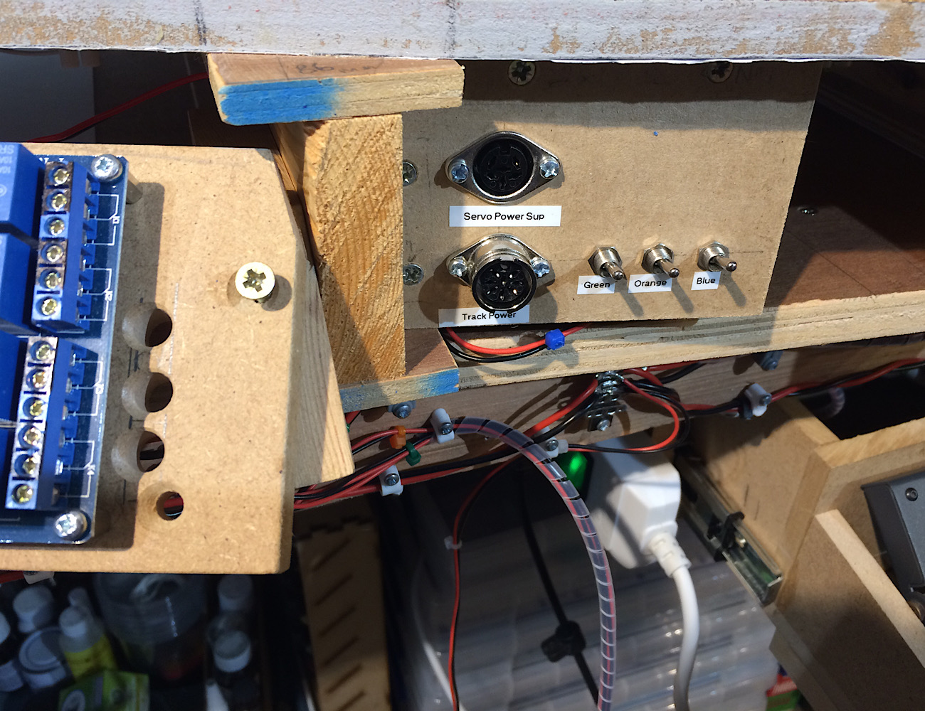 The rear of the above 2787_221517_520000000.jpg 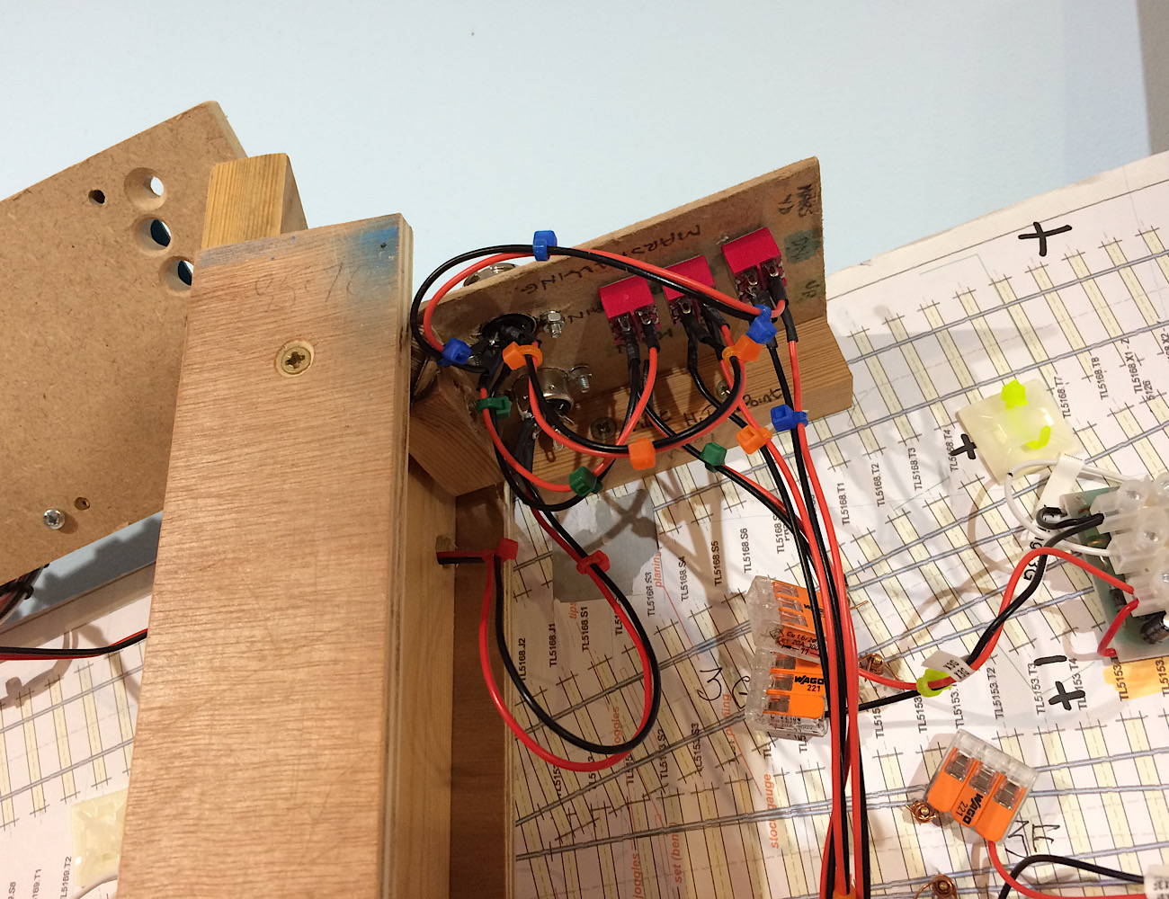 The three districts all go through this choc block strip. Here I’m using 16/0.2 flex, and for some short feeds from here to the rails (length 15” max) I’ll go down to 7/0.2 flex. 2787_221519_130000000.jpg 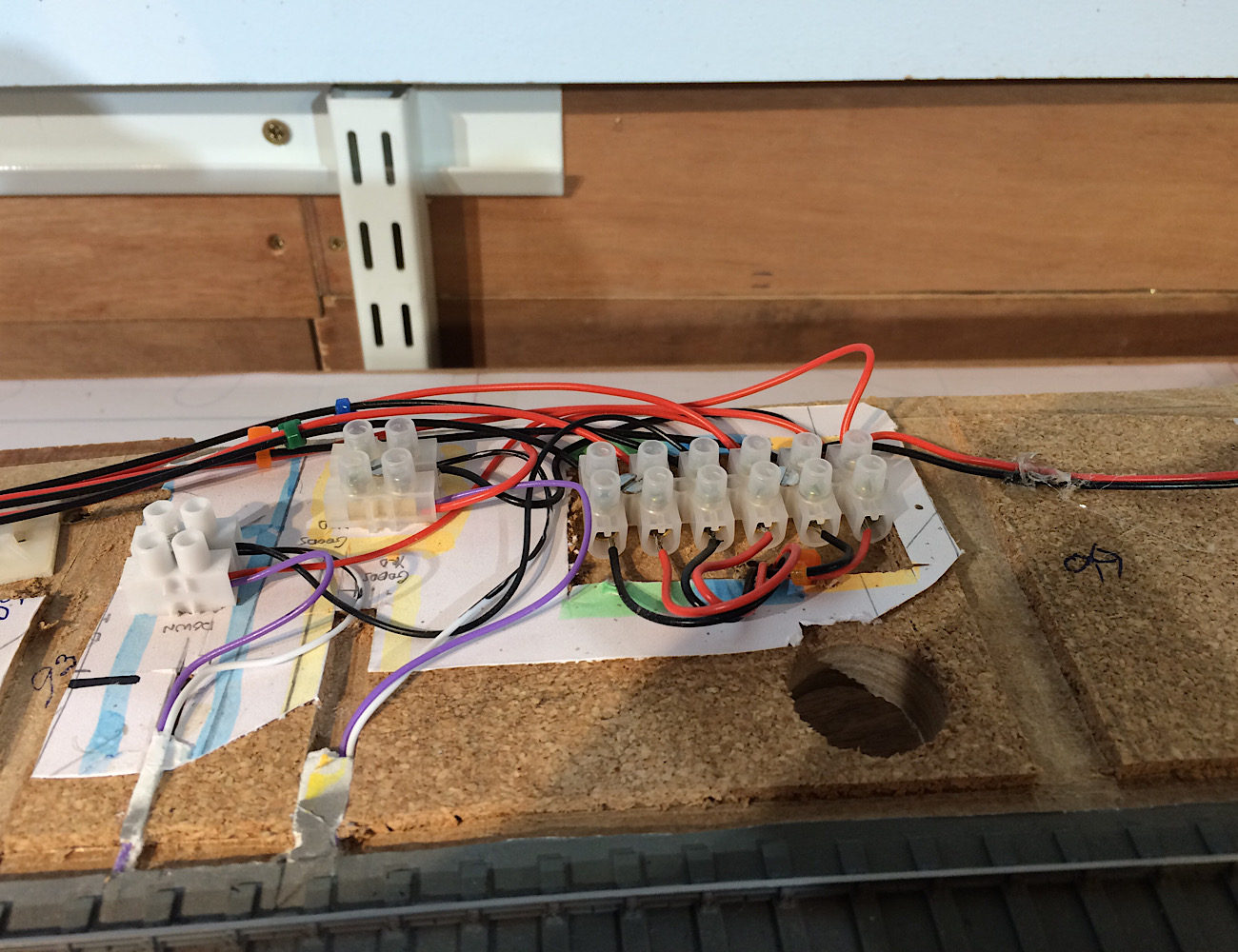 Ideas gratefully received Thank you Andrew |
||
|
posted: 23 Apr 2020 05:09 from: Andrew Barrowman
click the date to link to this post click member name to view archived images |
Hi Andrew, Your wiring looks good. If the district that's giving you the problem is not the furthest from the power supply it's more likely a suspect district cutout. Can you swap the cutout with another and to see if the problem follows that cutout or not? Do the MERG guys say their cutout is compatible with your "frog juicers"? Cheers, Andy PS - I had a MERG membership for a while but I had to give it up before it gave me a heart attack |
||
| Last edited on 23 Apr 2020 05:20 by Andrew Barrowman |
|||
|
posted: 23 Apr 2020 08:43 from: Andrew Duncan
click the date to link to this post click member name to view archived images |
Andrew Barrowman wrote: Hi Andrew,Hello Andy Thanks for your thoughts. Each district cutout is wired roughly the same distance from the the ZTC 511 as each other give or take an inch or two. So I'll try the local district switch first (local and specific to this baseboard) and its relatively easy to do. If no joy I'll try the swapping the district cutout for one of the others and this I hadn't clocked, so thank you for alerting me to this. And I'll ask on the Merg forum, where they are also very helpful, if there are any comparability issues with the AutoFrog. and actually whilst I'm at it I'll also ask about the sensitivity on the cutout which is currently the default setting which I know is very high ie very sensitive. Thanks again, kind regards and keep safe in these challenging times. Andrew |
||
|
posted: 23 Apr 2020 09:28 from: FraserSmith
click the date to link to this post click member name to view archived images |
Andrew Are you sure that you have set the short circuit delay jumpers the same on every DCO? |
||
|
posted: 23 Apr 2020 10:11 from: Ian T
click the date to link to this post click member name to view archived images |
Hi, I've got no understanding of DCC but I know a little bit about wiring. I don't use Choc Blocks whenever I can avoid them. They are designed for mains single strand wiring of either 1mm or 2.5mm and as such aren't suitable for small multistranded wiring. If they are unavoidable then it is much better to use ferrules to spread the load. I use 5mm Terminal blocks soldered back to back on stripboard and these can be used in a variety of configurations ie one in one out or ganged together as needed. (See attached) I also use ferrules wherever I can in TBs (unless it's single strand wire.) 2083_230510_300000000.jpg  It's difficult to see clearly in your photos but I have a suspicion that some of the wires in the TB have been tinned. If so that is a bad idea since the solder is so soft that through time it will get more compressed and eventually result in a bad connection. HTH Regards Ian Trotter |
||
|
posted: 23 Apr 2020 11:40 from: FraserSmith
click the date to link to this post click member name to view archived images |
Hi again Andrew Further reading of the DCO instructions says "Therefore it is inadvisable to use cabling with cores of cross-section area lighter than 1.5sqmm or 16AWG and preferably much more substantial than that in order to render the lowest possible loop resistance. In any case the DCO short-circuit protection must operate at any and every point in its sub-district and it is advisable that this is tested before every operating session." Your 16/0.2 wires are only 0.5mm^2 so that may also be a factor. I would also agree strongly with Ian's suggestion of ferrules for cable ends. I dismissed them as unneccessary for a long time but once I tried them I was hooked. They make connections so much easier and secure. From RS 178-7280 for 7/0.2 and 178-7288 for 16/0.2 for instance. They are available in different lengths. Make sure you are sitting down when you look for the crimping tools. Having said that if you are only using these on the smaller wires then the (much cheaper) non ratcheting type sould be fine. For my DCC power bus I use stripped out cores from 2.5mm^2 ring main twin and earth (the earth can be used for tree armatures). Feeds to DCOs can be taken off that in stripped out 1.5mm^2 lighting cable. Cheers Fraser |
||
|
posted: 23 Apr 2020 15:51 from: Tony W
click the date to link to this post click member name to view archived images |
Hi Andrew. 1.5mm sq is pretty hefty cable. 32/02 is 1mm sq and that is rated at 10 amps. Total loop resistance is obviously important not to limit current flow, but recommendations like that have to be generalised as some layouts get very large. Think American. As already mentioned, soldering stranded wire for use in screw terminals is not to be recommended as it invariably leads to problems sooner or later. DCC is not my field, but there is something that occurs to me based on the way both these units operate. Both are looking to detect high current flows, one to switch polarity and the other to shut the power off. It therefore stands to reason that the frog switcher must be the more sensitive to react faster than the DCO or strange things may happen. Regards Tony. |
||
|
posted: 23 Apr 2020 23:11 from: Andrew Duncan
click the date to link to this post click member name to view archived images |
Ian T wrote: Hi,Hello Ian Thanks for your thoughts and advice on chocolate blocks. My experience of them is not bad generally but I like the idea of the ferrules and the fact that you colour code them and if that makes for a better connection as well thats a win win. Kind regards Andrew |
||
|
posted: 23 Apr 2020 23:57 from: Andrew Duncan
click the date to link to this post click member name to view archived images |
FraserSmith wrote: AndrewFraser You and Tony have hit the nail on the proverbial head, spot on. Well done chaps!! I had on investigation left the District Cut Outs (DCO) as I built them with no increase in the time lapse straight out of the box (well kit of parts). So having faffed around earlier today with the switch for that district on this board, in the end to no avail I turned my attention reluctantly to the four DCO's. I'm sort of scared of electronics as I don't understand any of the principles and therefore have no personal resource on which to call if something goes wrong, very different to tracing a short circuit in a turnout. The fact that I built 4 DCO's without problem, beating the wife or crucifying the children is a testament to their design, detailed instructions and the helpful people on the Merge forum! However when you asked about the delay jumpers a light bulb somewhere in the depths started to glow very dimly at first. To cut a short story, shorter, I ended up installing a delay jumper at its lowest level of sensitivity and suddenly the Autofrog relay started working as its should and click over. What a relief....Brilliant! So a very big thank you Fraser to you for asking the right question and to both of you for spotting what area my problem was coming from. Tony you were spot on when you said that the Autofrog had to switch faster than the DCO. Well it didn't and that was the problem. Now it does! In my case as is so often the case in life, its not what you know, its who you know. Thanks again everyone. Kind regards Andrew |
||
|
posted: 24 Apr 2020 15:52 from: Tony W
click the date to link to this post click member name to view archived images |
Hi Andrew. Just glad you've been able to sort the problem out. That tends to be the problem with high tec equipment. Great when it works, but when it doesn't; HELP! Regards Tony. |
||
| Last edited on 24 Apr 2020 15:52 by Tony W |
|||
|
posted: 26 Apr 2020 23:24 from: Andrew Duncan
click the date to link to this post click member name to view archived images |
Tony W wrote: Hi Andrew.Exactly!!! Here’s picture or two of progress this weekend, but before that it’s showing off time again with our Azaleas just bursting into flower. Photographically I can’t compete with Martin, Nigel et al over in “ Fresh air and photos” so it stays here incongruously! 2787_261758_570000000.jpg  And here’s a part of breakfast this morning, or what was left after we demolished fair proportion of Jeanne’s home made Croissants, Pain aux chocolats and Pain aux raisins. There are some quite tangible benefits to the lockdown when one has a talented pastry chef living on site! 2787_261804_450000000.jpg  Sorry there aren’t photos of the first two items on the menu but they did exist. And here’s a photo of the revised lowered bank after Martin’s comments and me looking at the photos that I have from that period with a fresh eye. I think it looks much better with shallower angle and the field at the top of the embankment significantly lower. And I found a good photo of the stair case that rises from track level up to the road above. In my photo it shows it with wooden handrail on both sides and dated early 70’s. So I’m wondering if that was likely to be the original one or whether for the year I’m modelling (1922) it might have been a metal railing? Anyone got any ideas or educated guesses? 2787_261818_340000000.jpg 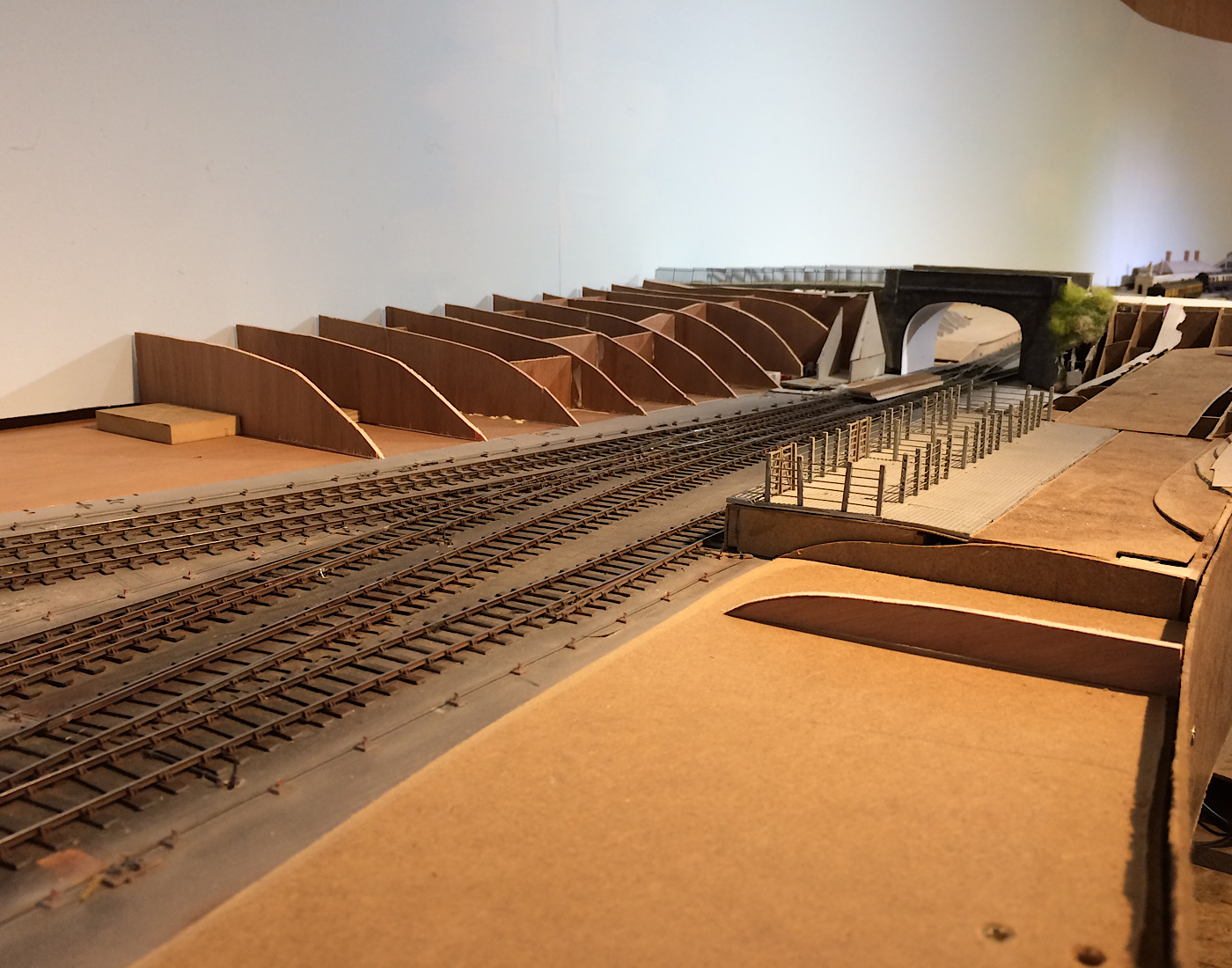 That’s it for tonight. Kind regards Andrew |
||
| Last edited on 26 Apr 2020 23:27 by Andrew Duncan |
|||
|
posted: 27 Apr 2020 07:05 from: FraserSmith
click the date to link to this post click member name to view archived images |
Hi Andrew That's looking quite impressive now but the civil engineer in me sees your profiles slightly differently. The railway will have been placed into position by removing ground to provide the cutting. That cutting would have had a fixed gradient for the location to suit the material involved. When performing the cut, that batter would extend up until it met the original surface at an immediate change of angle. It would not be rounded off as you have with most of your profiles except the nearest two. The existing conifers and undergrowth in and at the top of the cutting will be masking that now but in the period you are modelling it would likely have been clear and pristine. I hope that you don't take this as criticism of your efforts but as a suggestion of improving the realism of the environment in which your immaculate railway sits. Cheers Fraser |
||
|
posted: 27 Apr 2020 23:33 from: Andrew Duncan
click the date to link to this post click member name to view archived images |
FraserSmith wrote: Hi AndrewHello Fraser To answer your last remark first, no I don’t take offence. Yes it’s critical but as I read it, of a constructive nature and intent and I’m very grateful to you for your observations. The reason I’d made those last two profiles more angular was that I had a photo of the embankment further along and the sharpness of the change in gradient was very marked, rather I think as you were suggesting it all was likely to be. So as I read through what you wrote it made sense to me that it would all be the same angle and the sharpness of angle change would be just as marked where the embankment is higher closer to the bridge. I’ve done some reprofiling of the profiles which I now think is probably closer to reality and added a few more. Let me know what you think. 2787_271828_120000000.jpg 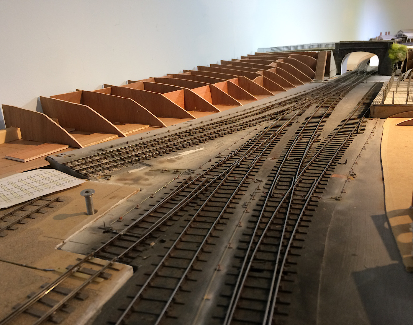 Looking at the photo it appears that the profiles close to the camera are taller than ones further away. In fact they are a smidgen lower. Kind regards Andew Edited for missing a word |
||
| Last edited on 28 Apr 2020 18:57 by Andrew Duncan |
|||
|
posted: 28 Apr 2020 06:59 from: FraserSmith
click the date to link to this post click member name to view archived images |
Hi Andrew That looks much more like the boss of the civil engineering company that did the works would have liked to see. No excess works that he wouldn't get paid for. Having that sharp angle keeps the land take to a minimum so keeping the railway's costs down too. It also gives you a definte line to follow with your boundary fence. Civil engineering earthworks can look quite brutal. New roads projects today still use the same approach and looking along a cutting face you will see the same smooth continuous surface cutting up to the existing ground. Working the way modellers have to do from baseboard up makes it more difficult to get such things right. Perhaps a good way to do such profiles would be to cut them to length and cut the top surface to the desired shape to suit the orignal ground then use a mitre square to mark the slope and cut off the "excavated material". I look at layouts in Railway Modeller and often see great efforts made with a railway with finely detailed stock and buildings but let down by their civil engineering. Bridges with no bearings under the girders at the abutments and piers, plate girders with stiffeners in the wrong places or none where there should be, through truss bridges with a support not at a bottom node to name but a few. To me these are just as important to get right as all the rest of a layout but I can appreciate that what is obvious to me or another civil engineer would not be noticed by many people. Keep up the great work. I enjoy seeing your progress. Fraser |
||
|
posted: 28 Apr 2020 08:18 from: Martin Wynne
click the date to link to this post click member name to view archived images |
Hi Andrew, Continuing Fraser's civil engineering theme, that elliptical bridge arch looks just a bit too flat to be comfortable. The radius in the haunches is usually smaller. But it may be the angle of your photo? mrwo1745.jpg 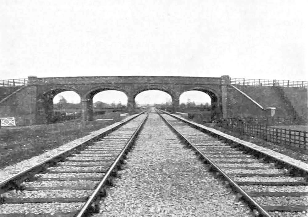 linked from http://www.warwickshirerailways.com/lms/mr/waterorton/mrwo1745.jpg cheers, Martin. |
||
|
posted: 28 Apr 2020 08:31 from: Phil O
click the date to link to this post click member name to view archived images |
Isn't that what they said about IKB's bridge at Maidenhead and that's still standing. Phil |
||
|
posted: 28 Apr 2020 11:17 from: Hayfield
click the date to link to this post click member name to view archived images |
I know nothing about structured but is it not the 4 arches that make up the strength of the structure | ||
|
posted: 28 Apr 2020 11:40 from: Martin Wynne
click the date to link to this post click member name to view archived images |
Hayfield wrote: I know nothing about structured but is it not the 4 arches that make up the strength of the structureHi John, In an arched viaduct, the outer arches push against the abutments, which need to be solid enough to withstand the force. The inner arches push against each other, so that the sideways forces cancel out and there is no sideways force on the piers. That means the piers can be quite slender, needing only to support the weight. But it also makes a viaduct vulnerable -- if one arch collapses for any reason, many of the others are likely to collapse too. cheers, Martin. |
||
|
posted: 28 Apr 2020 22:45 from: FraserSmith
click the date to link to this post click member name to view archived images |
Just to add to the arches debate, many, many "elliptical arches" aren't elliptical but three or rarely five centered. They have a large radius to the centre section that joins to smaller radius section(s) towards the springings. Much easier to make the centring for and only two (or three) different shapes of voussoirs rather than every course being different to each other as the effective radius changed from small to large. Martin's description of how a viaduct works is fine until you put 100 ton loads over the comparatively short length covering two adjacent bogies of a mineral or tanker train or something like a King or Duchess. Then there is quite a different horizontal load generated in that loaded span compared to the adjcent ones. The spandrel walls will take some of that force but the imbalance will cause the top of the piers either side of that big load to move outwards. It's only a small distance but they do move out and that movement will lift the crown of the adjacent span. In 1846, Barlow demonstrated how an arch can sustain many different thrust lines. In the unloaded condition the thrust will be near the top of the arch ring in the centre of the span and near the bottom of the ring at the supports. The thrust line is more curved that the centre line of the arch ring. In that state the arch is exerting its minimum thrust on its abutment or pier. In 1676 Robert Hooke discovered something fundamental about arches and published it as a Latin anagram at the end of a paper on Helioscopes (http://quod.lib.umich.edu/e/eebo/A44317.0001.001/1:6?rgn=div1;view=fulltext) in 1676. It translates as "as hangs the flexible line, so but inverted will stand the rigid arch. He did this to prevent Newton claiming this discovery as his own as he was apparently wont to do. When the arch gets squeezed by the adjacent arch pushing it it reacts by moving up at the crown and that causes the thrust line to move towards the bottom of the ring at the crown and towards the top of the ring at its supports. The thrust line is then less curved that the ring centre line. The increase in the horizontal component of that thrust line in that condition is quite significant provided that the arch ring is deep enough. It is easy to see this effect as to hold a hanging chain with a biggish dip is much easier that to try and hold it with a shallow dip in it. What is tension in the chain becomes compression in the arch ring. Think Royal Albert bridge where the outward force in the tubular arch is balanced by the inward pull of the ends of the chains. If the outward force exerted by a span is suffiicient to cause the adjacent span to lift sufficiently it will get to the point where the thrust line cannot stay within the arch ring and shall we say you wouldn't want to be standing underneath it at that stage. Whilst on the topic of bridges and viaducts, there was almost always a big chunk of masonry composed of the waste from dressing the stones or additional courses of brick built over the arch ring at piers. The extra weight was useful but this construction in effect moved the springings out to the end of that reinforcement. The effect of that externally is that generally there will be lime streaks down the spandrel walls from that level caused by water getting into the arch fill exiting it at that level. The masonry above and below that backing will also exhibit different lichen growth etc and is usually a slightly differnt colour due to dampness encouraging algae etc. I've not seen this modelled on any layout I've looked at. On a similar theme, I watched a video of Pete Waterman's as accurate as possible railway and his tunnel entrance has coursed masonry but no arch ring to hold up that masonry or indeed the material over the tunnel!!! Yes, arches are fascinating. Cheers Fraser |
||
|
posted: 28 Apr 2020 23:22 from: Rob Manchester
click the date to link to this post click member name to view archived images |
FraserSmith wrote: Fraser, That is very impressive for two reasons - (1) your depth of knowledge (2) it is one of the first posts on Templot that even Martin Keep safe. Rob (..in a very wet Manchester for a change |
||
|
posted: 28 Apr 2020 23:38 from: Andrew Duncan
click the date to link to this post click member name to view archived images |
FraserSmith wrote: Hi AndrewHello Fraser Thanks again for your thoughts and professional guidance and your encouragement. I’m glad you’re enjoying it Here’s another progress photo. There’s still a little refining to do but I think it’s taking shape nicely now. Photo taken from the Sherborne road bridge. Kind regards Andrew 2787_281835_130000000.jpg 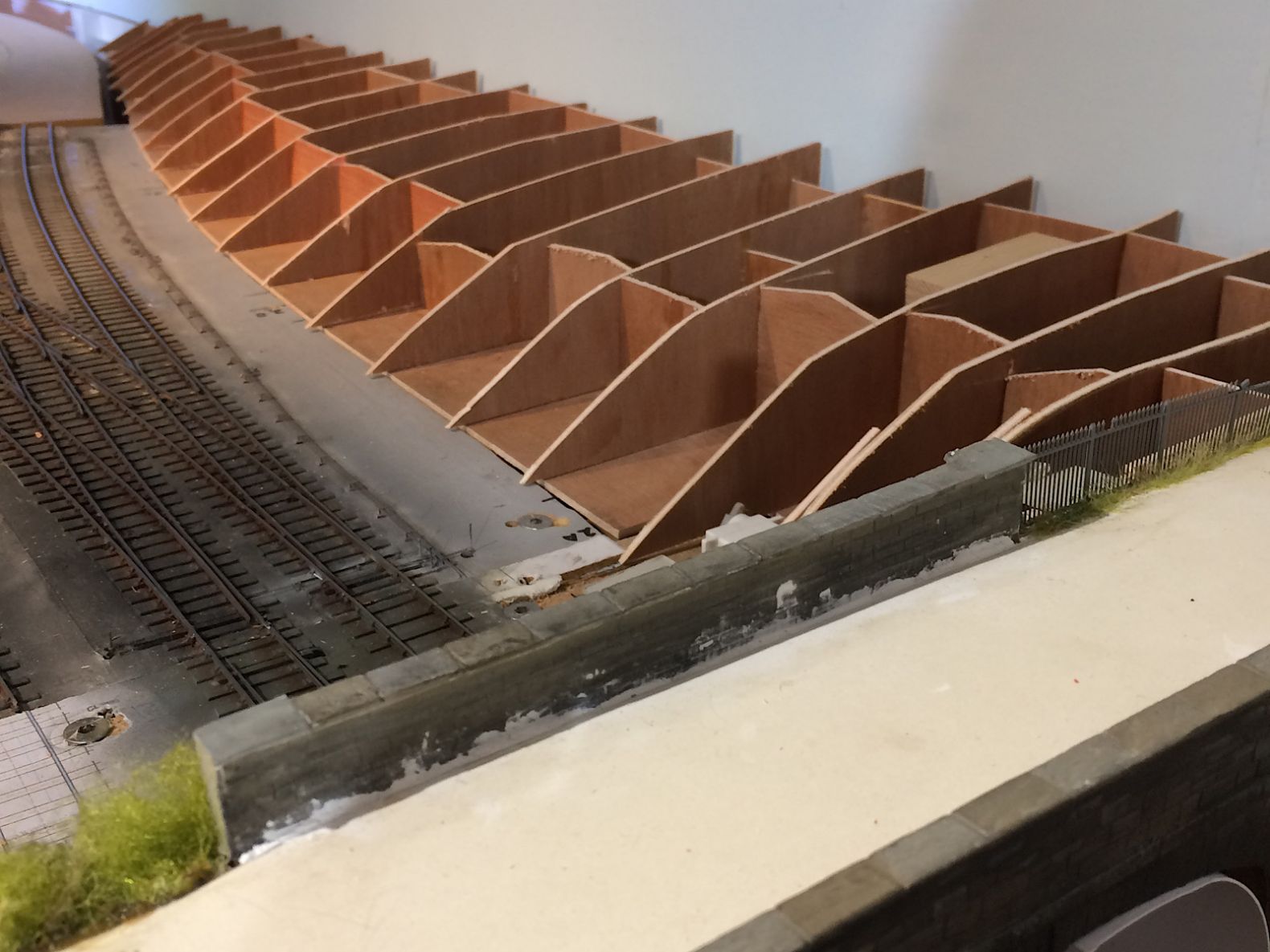 |
||
|
posted: 29 Apr 2020 00:09 from: Andrew Duncan
click the date to link to this post click member name to view archived images |
Martin Wynne wrote: Hi Andrew,Hello Martin Thanks for your post. I do hope it was the photo that made it look a little flat. It prompted me to check the photo I have of the real bridge and compare it with my model. Here are a couple of shots. The first is the model that has a white card infill (not yet properly stuck in place) on the right hand side of the arch. There because on Yeovil Mk1 ( which the bridge was made for originally) it couldn’t be seen and Iain, being an 80/20 modeller, didn’t model anything unnecessary. So that does not help the clarity or outline of the arch but I think I can live with it. 2787_281853_300000000.jpg 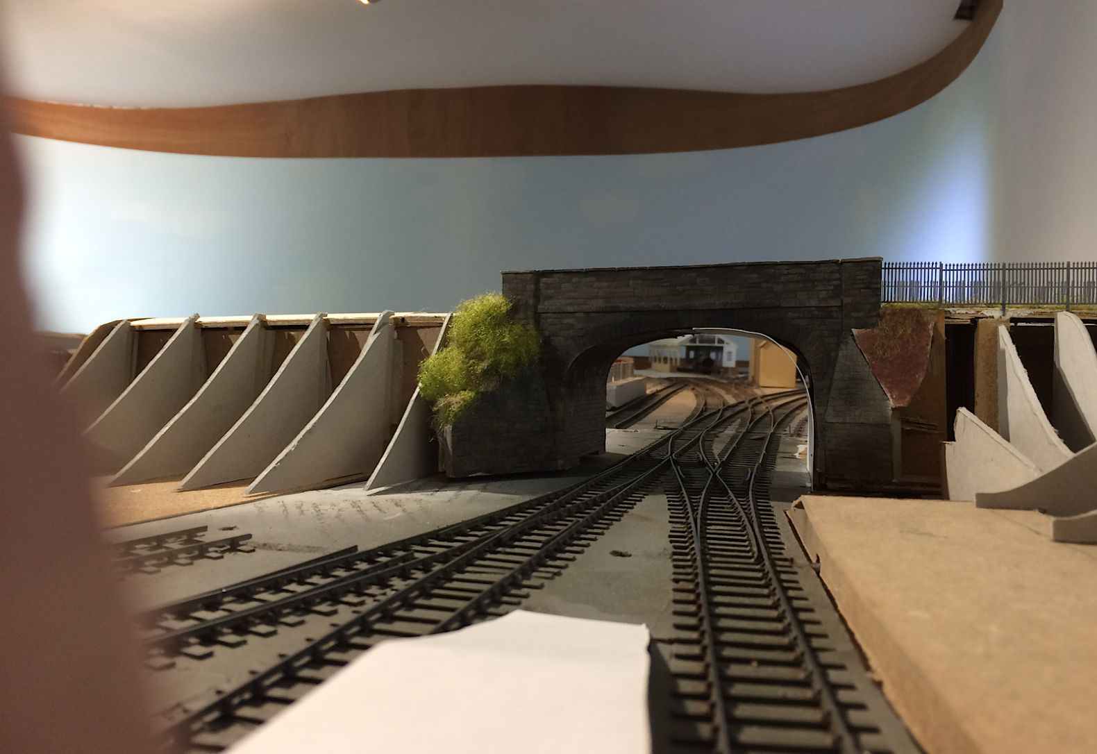 And this one is obviously the real,thing....I’ve got a long way to go! Kind regards Andrew 2787_281903_260000000.jpg 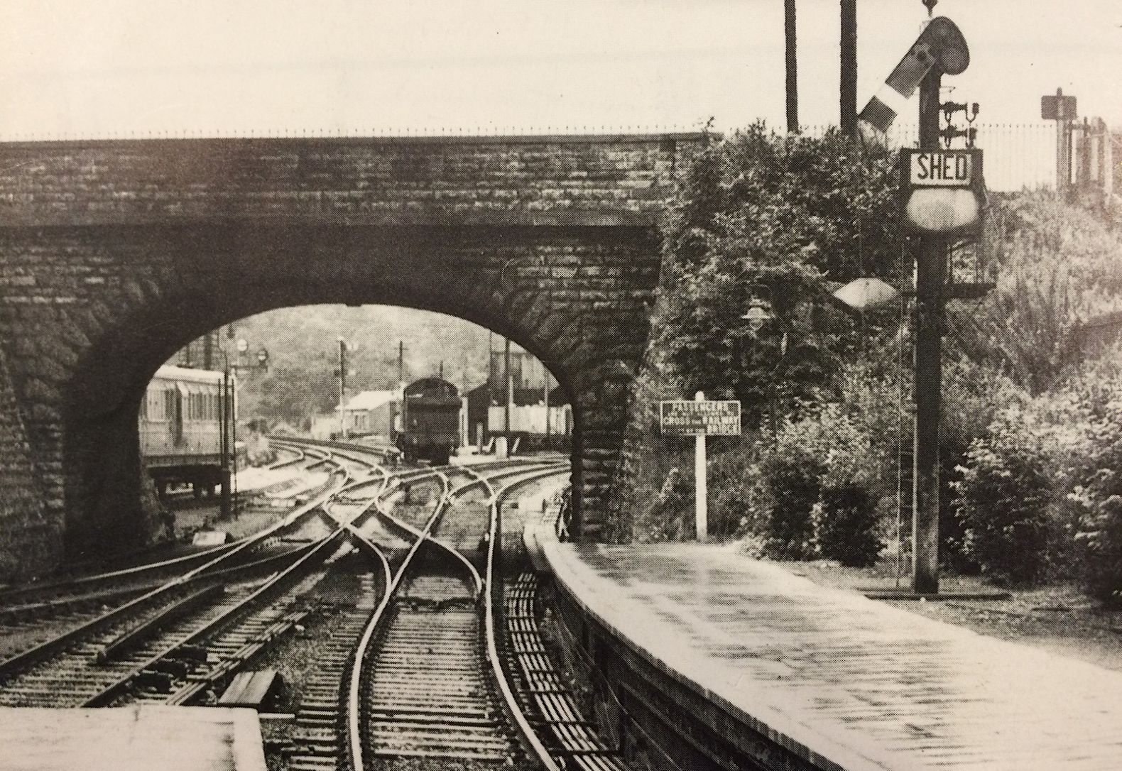 |
||
|
posted: 29 Apr 2020 00:18 from: Andrew Duncan
click the date to link to this post click member name to view archived images |
Rob Manchester wrote: FraserSmith wrote:Hello RobFraser, i agree with your summing up, impressive to say the least, A sort of Martin Wynne of the civil engineering world, Andrew, from a very wet Reigate |
||
|
posted: 29 Apr 2020 00:29 from: Martin Wynne
click the date to link to this post click member name to view archived images |
Andrew Duncan wrote:It prompted me to check the photo I have of the real bridge and compare it with my model. Here are a couple of shots. The first is the model that has a white card infill (not yet properly stuck in place) on the right hand side of the arch.Hi Andrew, Thanks for the pics, but I didn't quite follow that? The masonry as modelled is clearly fine -- it wasn't clear in the previous photo. But that piece of card is all wrong. The radius in the haunch is too large, and along the top there appears to be a horizontal section, which was confusing me in the previous photo. Even the flattest masonry arch doesn't have a horizontal section in the middle. Many thanks to Fraser for such a detailed explanation of arches. cheers, Martin. |
||
|
posted: 29 Apr 2020 07:04 from: FraserSmith
click the date to link to this post click member name to view archived images |
Hi Andrew The new photo from the bridge does indeed show a much better alignment of the battered cutting side. Your arch bridge shape also looks fine but shall we say that the Sherborne Road embankment profiles may need a bit of help from a length of straight edged card glued to the existing. It's interesting to see in your actual arch photo above that there is a distinctly darker patch of masonry from each springing upwards about three feet where there would be that masonry backing I described above. The knowledge of arches probably comes from my PhD studies in the late eighties/early nineties that culminated with a thesis entitled "Load Path Analysis of Masonry Arch Bridges". This came about when I changed horses from contracting (including setting out cuttings for road construction) to University life when I got a post doc position (but without holding a PhD!) assisting a member of staff who was developing a computer program to analyse/assess arches. He now has his own consultancy and I still work with him when they have jobs including monitoring active railway arches. Active is the right term as well as I have seen videos of movement across a crack in an arch and a skewback of a viaduct moving backwards and forwards as trains passed over. During my study period the Transport and Road Research Laboratory had a program of eight tests to destruction on redundant arches and one brand new one that was built on the test floor in our laboratory at Dundee where my contracting experience proved very useful. 3137_290125_120000000.jpg  3137_290125_120000001.jpg  The shiny discs were home designed pressure cells to measure the contact pressure between the fill and the arch ring. I also watched the demolition of an arch at Cargill on the old Caly main line from Perth to Aberdeen that was just up the road from where we lived at the time. A lot of time and money was wasted installing explosives into the arch when all that's needed is to simply lift the crown. Anyway the photo below shows the digger sitting on the solid masonry backing above and behind the abutment. 3137_290125_120000002.jpg  It looks like I will be on site assisting with the monitoring of a railway viaduct later in the year when these current restrictions are lifted. As I said, arches are interesting. Cheers Fraser |
||
|
posted: 29 Apr 2020 23:25 from: Andrew Duncan
click the date to link to this post click member name to view archived images |
Martin Wynne wrote: Andrew Duncan wrote:Hello MartinIt prompted me to check the photo I have of the real bridge and compare it with my model. Here are a couple of shots. The first is the model that has a white card infill (not yet properly stuck in place) on the right hand side of the arch.Hi Andrew, I’ve now stuck a new piece of card in place, properly and trimmed to size properly! And here it is sitting on the edge of the layout where the light is better. Tell me what you think, does it throw light on my lack of clarity previously? Kind regards Andrew 2787_291821_150000000.jpg 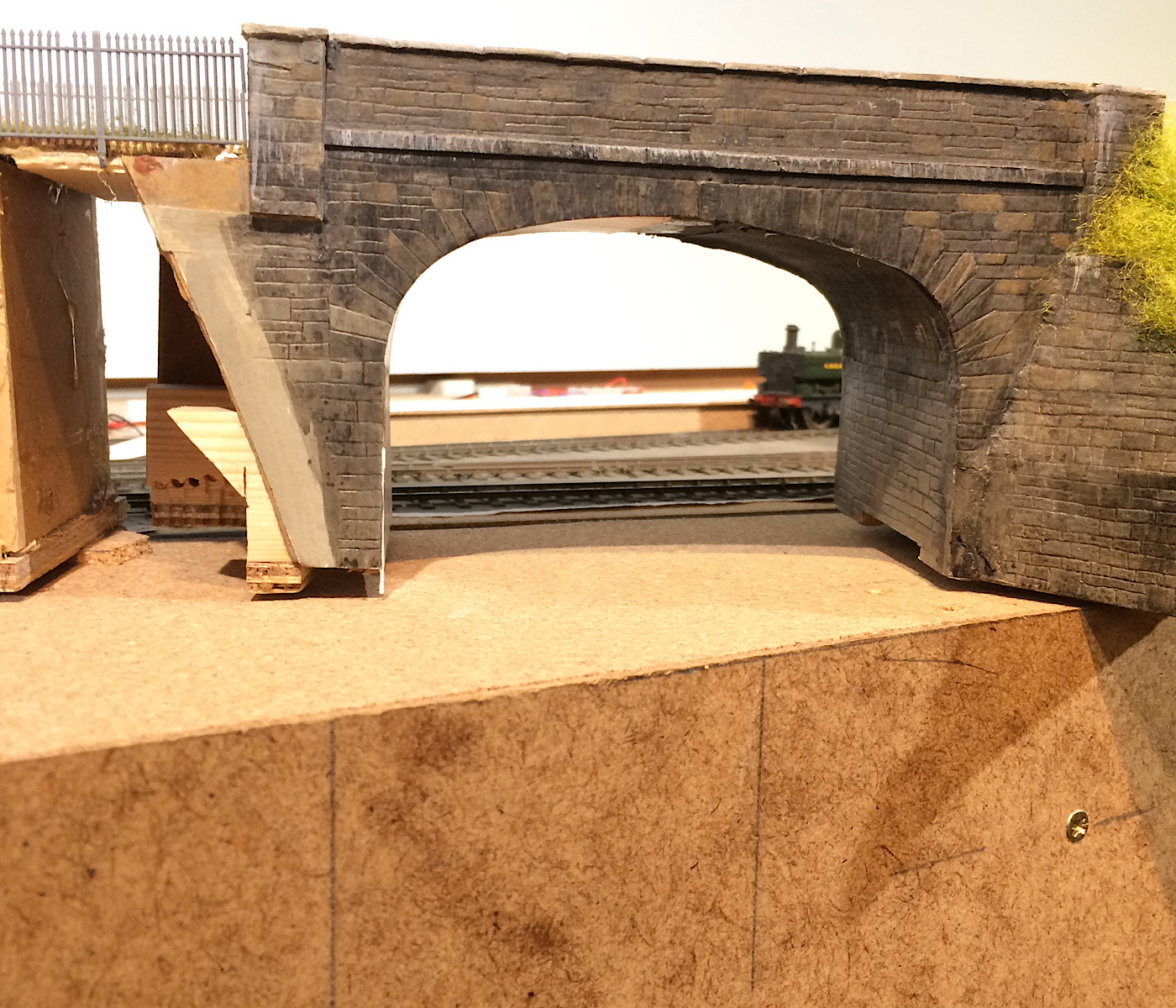 |
||
|
posted: 29 Apr 2020 23:55 from: Andrew Duncan
click the date to link to this post click member name to view archived images |
FraserSmith wrote: Just to add to the arches debate, many, many "elliptical arches" aren't elliptical but three or rarely five centered. They have a large radius to the centre section that joins to smaller radius section(s) towards the springings. Much easier to make the centring for and only two (or three) different shapes of voussoirs rather than every course being different to each other as the effective radius changed from small to large.Hello Fraser This is a really interesting read in many ways but quite often your terminology looses me. I’m wondering if you’d be persuaded to do me a drawing to go with your descriptions. As well as terms like Voussoirs, Spandrels, sentences such as “ the thrust line moving towards the bottom of the ring etc” “the increase in horizontal component of that thrusts etc is rather puzzling stuff to a simple retailer. I’d very much like to understand more of what happens to a bridge arch as heavy loco travels over it. Sounds like it moves in some unexpected directions but I can’t say yet that I could articulate what they are. If I don’t hear from you I’ll assume that my request was a bridge too far.... Kind regards Andrew |
||
|
posted: 30 Apr 2020 00:11 from: Andrew Duncan
click the date to link to this post click member name to view archived images |
FraserSmith wrote: Hi AndrewHello again Yup I take your point about the curvy nature of the embankment. I shall get on it tomorrow without fail! Funny that, I’ve already added to those profiles as I got them far too steep at first, and Martin pointed that out last week, so amended them with extra card. Now they’ll be getting their second addition and maybe a touch more slope. Another terminology question. What is the Springing? Andrew |
||
|
posted: 30 Apr 2020 07:41 from: FraserSmith
click the date to link to this post click member name to view archived images |
Hi Andrew I'll find some diagrams to illustrate what I heve been describing and put them up here with an appropriate description. I can't easily use any from my PhD as most were created in HPGL (Hewlett Packard Graphics Language for pen plotters) and not many applications these days use that format. Your embankment slopes would normally be between 1:1.5 and 1:2. The springing is the point that the arch springs from i.e. the lowest point of the arch. Fraser |
||
|
posted: 30 Apr 2020 09:44 from: Andrew Duncan
click the date to link to this post click member name to view archived images |
FraserSmith wrote: Hi AndrewOk Fraser that very kind of you, I'll look forward to seeing them and gaining greater understanding when you have a moment Kind regards Andrew |
||
|
posted: 3 May 2020 14:12 from: Martin Wynne
click the date to link to this post click member name to view archived images |
Hi Andrew, Any plans to extend to Yeovil Town? Have you seen this? Shunting Yeovil Town Coal Yard in 2mm scale: Martin. |
||
|
posted: 3 May 2020 15:23 from: Charles Orr
click the date to link to this post click member name to view archived images |
Martin That is absolutely fascinating. I wonder how the tractor is controlled? Charles |
||
|
posted: 3 May 2020 15:28 from: Charles Orr
click the date to link to this post click member name to view archived images |
I only got to 9 minutes when i sent the last post...... He does explain later |
||
|
posted: 3 May 2020 23:50 from: Andrew Duncan
click the date to link to this post click member name to view archived images |
Martin Wynne wrote: Hi Andrew,Hello Martin No none I’m afraid. Already feel, every so often, that I’ve bitten off more then I can chew, what with a change in gauge and my rather slow progress with track building, but yes very impressive and all in 2mm! Bordering on the magical in fact. Kind regards Andrew |
||
|
posted: 4 May 2020 01:10 from: Rob Manchester
click the date to link to this post click member name to view archived images |
Martin Wynne wrote: Hi Andrew,Hi Martin, Thanks for posting that. I must say it is one of the best layout features I have seen for ages and it was attempted in such a small scale. Can't wait to see the contents of the cattle dock boarding the train and the milkman's horse drawn float. Rob |
||
|
posted: 4 May 2020 11:22 from: Tony W
click the date to link to this post click member name to view archived images |
The working shunting tractor is most impressive and in 2mm scale at that. Shunting tractors were used in the industrial area of my layout, but even in 4mm scale I bottled out of that challenge and made the area off scene. There were at least two Massey Ferguson tractors with buffing plates fitted at either end to push the wagons about. I don't recall any means of towing being used. The other memory I have is of them churning up the ground when trying to get more than a couple of wagons on the move at once. That area was well rutted and best avoided on a bike. Then I found out why. Regards Tony. |
||
|
posted: 16 May 2020 18:47 from: Andrew Duncan
click the date to link to this post click member name to view archived images |
Hello everyone Complete chaos reigns as you can see from the first picture. I’ve been putting off building the baseboards for the hidden track mainline that goes underneath the station( the plan is a folded figure of eight) and it requires me to gently raise the track bed under the station on a 1: 140 gradient moving to a 1:70 as comes out of the far end ( then under the single track line that goes to the LSWR station of Yeovil Town) climbs round the far end of the the layout before entering the fiddleyard. Getting the levels to not interfere with each other has been a bit problematic and also how to hide both it ( the main line) and the branch line above it is taxing my 3D imagination, so I’ve found myself mocking it up with bits of MDF and 4mm ply. So below the layout largely taken apart again to allow access to the hidden MDF track bed. In short a mess. 2787_161330_290000000.jpg 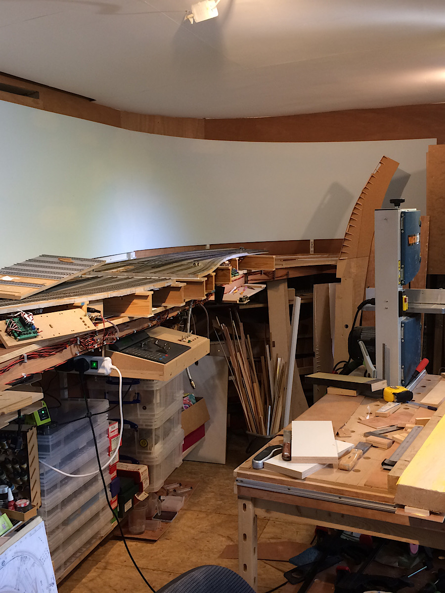 A shot of the 1:140 incline under the station. MDF with sides cut to the right gradient in 4mm ply leading to the problem area in the distance where it just misses the underside of the MPDs turntable. Phew! 2787_161625_250000000.jpg 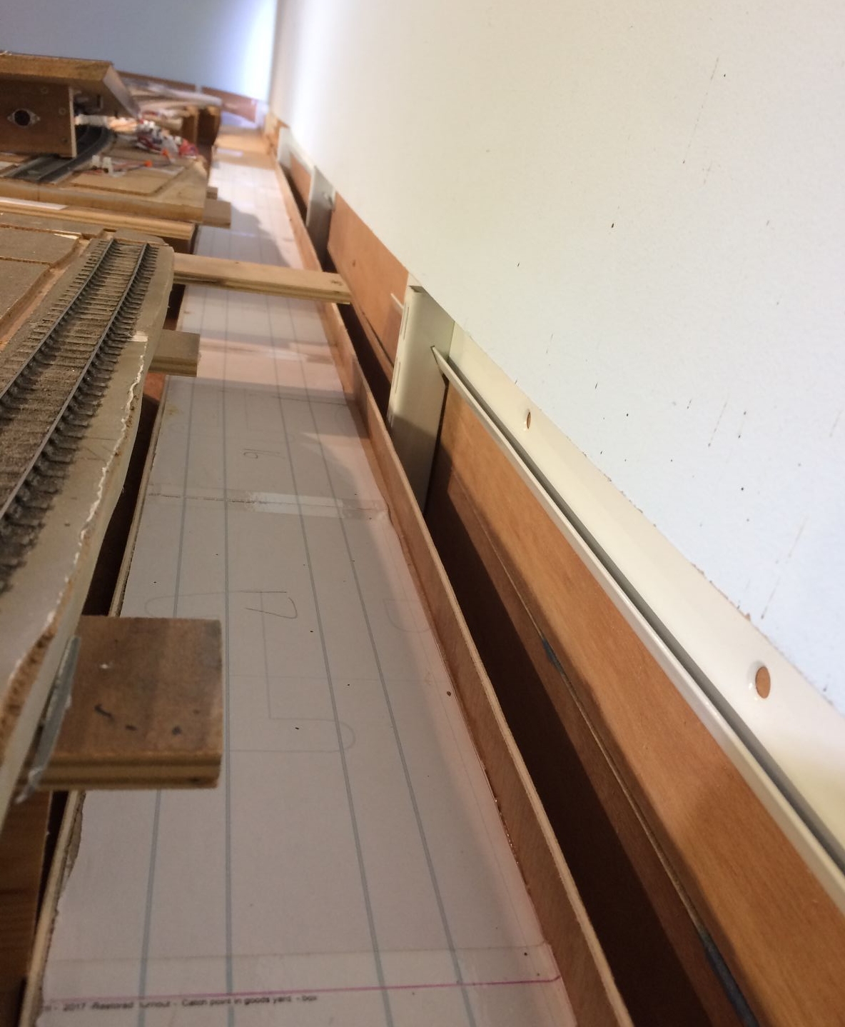 And lastly a view across the MPD with an experimental view blocker, shoved into place That’s it for now. Looks a bit depressing but in reality I’m making some progress. Just hope Phil at C&L can supply the track for it ok. 2787_161346_470000000.jpg 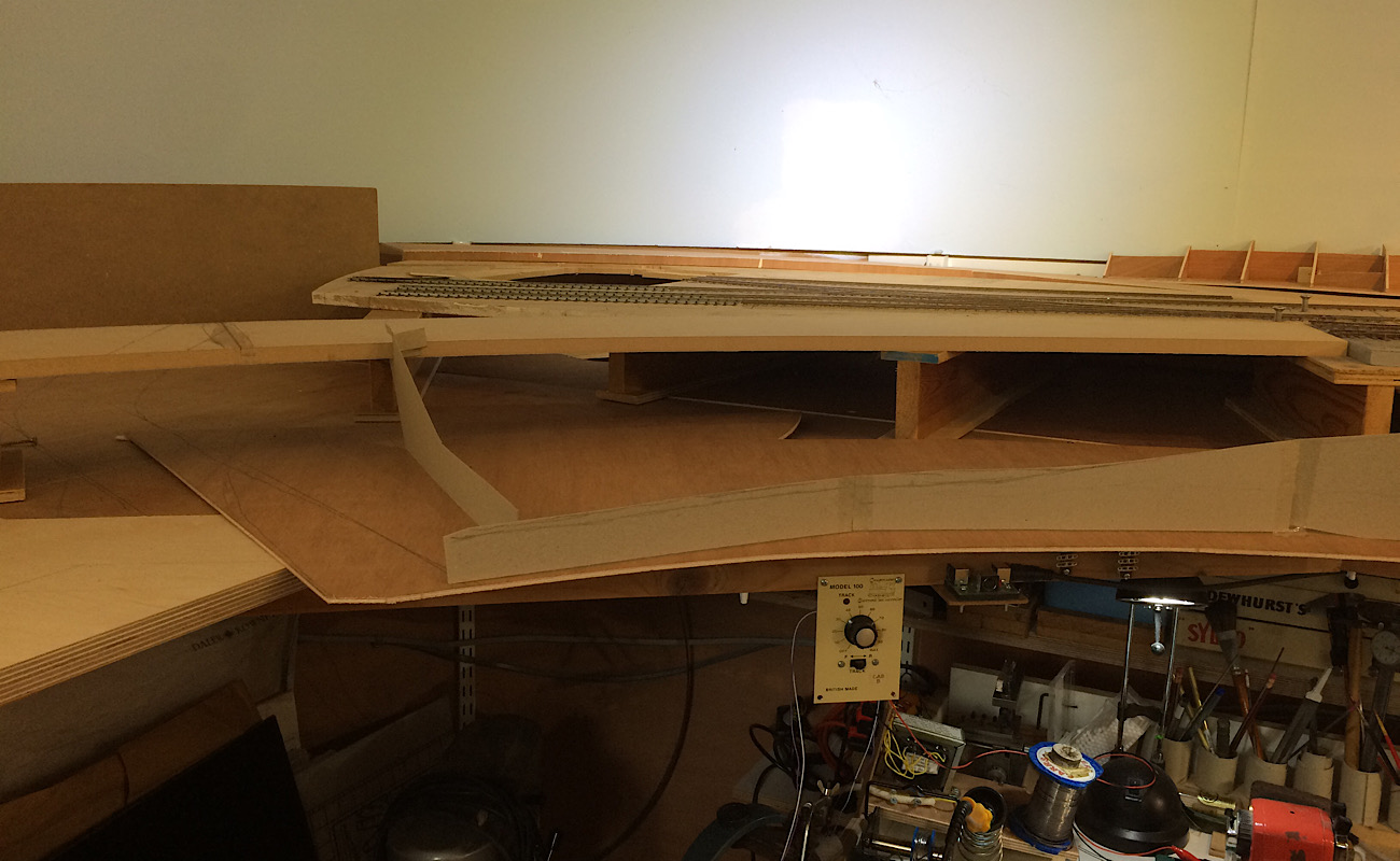 Kind regards and trust you’re ok. Andrew |
||
| Last edited on 16 May 2020 21:26 by Andrew Duncan |
|||
|
posted: 20 Jun 2020 13:54 from: Igor Kurgan
click the date to link to this post click member name to view archived images |
Andrew, Good job done! Very nice layout! It was a very good read, thanks for posting so much, got myself a idea or two. I can only hope that i will have a train running a year from now. Thanks for sharing, best |
||
|
posted: 4 Jul 2020 19:27 from: Andrew Duncan
click the date to link to this post click member name to view archived images |
Igor Kurgan wrote: Andrew, Hello Igor Thanks very much for the kind comments, much appreciated. Kind regards Andrew PS I'll try to post a few pics shortly of my somewhat limited progress... |
||
| Last edited on 4 Jul 2020 19:29 by Andrew Duncan |
|||
|
posted: 5 Jul 2020 19:03 from: Andrew Duncan
click the date to link to this post click member name to view archived images |
Hello Everyone A bit off progress that will be forever hidden from sight for the most part. Below the MPD pictured in this scene is the beginnings of the long gradient up from below the main station (to the right and off scene) This is the route south out of Yeovil to the fiddle yard. Which gradually climbs behind out of sight to regain datum/ station / fiddle yard height on the opposite side of the room from Yeovil. There’s no track yet and everything is just propped in position to see how it works with clearances and the hiding of the line at the back. 2787_051342_320000000.jpg 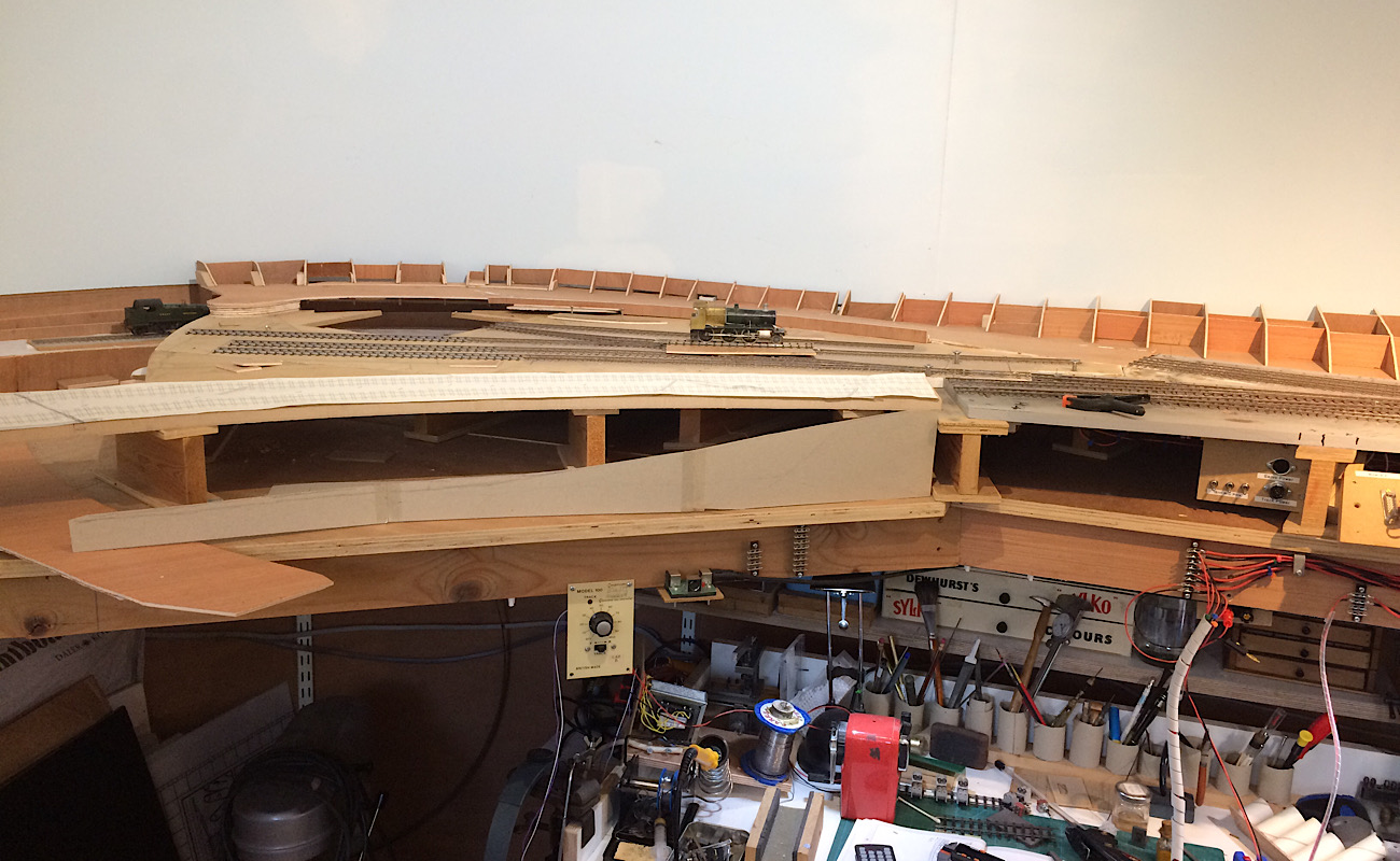 And this photo show it a bit further round with the south bound line in the foreground passing over the mill stream and a second bridge over the main river itself. And the “hidden lines “ as yet in full view behind. 2787_051342_320000001.jpg 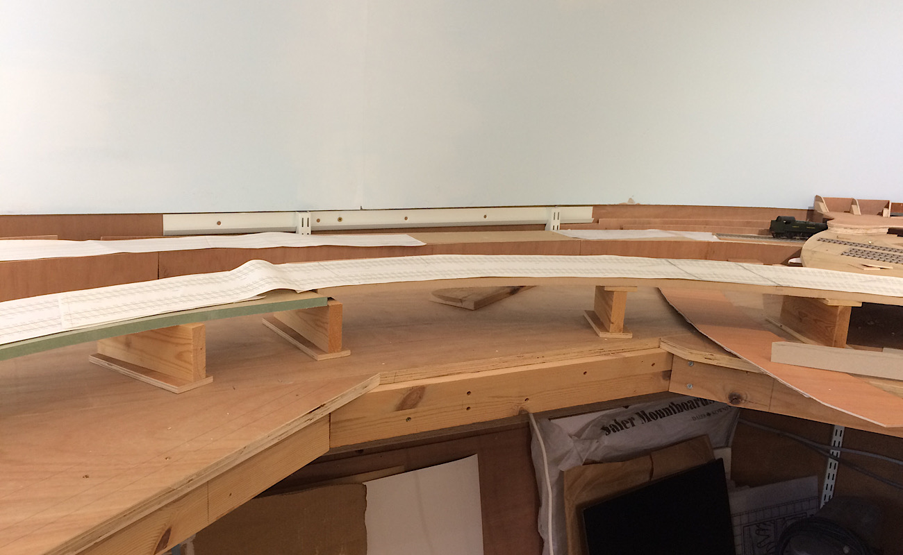 Well that it for now. Kind regards Andrew |
||
|
posted: 25 Oct 2020 18:16 from: Andrew Duncan
click the date to link to this post click member name to view archived images |
Well its seems to have been a very long time since I posted anything or made any progress, but I've been distracted by other things. For a starters the lockdown at its height made our websites so busy that they managed to make up for us have all three shops closed... We sell middle to high end cookware and of course with everyone locked in their homes, unable to spend money on going out or going on holiday, many decided it was time to invest in better cooking equipment, so from mid April to August we became frantically busy and this was a very welcome distraction, as you can imagine, and a completely opposite situation to the one we've been facing for the last 4 or 5 years which, I'll just say, has been challenging! When I sadly felt I must sell my old MGA about three years ago I didn't replace it with another "toy" because I wasn't sure the money might not be needed to buy stock with. But the last 5 or six months have meant things have changed and that I could feel safe enough to take a bit of the money from the sale, and to cut a long story short I've bought a 22 year old BMW E39 Alpina B10 3.2 in really nice nick. So as you might imagine this had also taken its toll on small trains time. I am now coming out the other side I think, and something prompted me to ring Iain the other day to ask him for his help again. And he's now hoping to come up in November, Covid allowing, so I'm hoping that this will lead to me reporting some proper progress in the next 3 or 4 weeks. Whilst thinking about my next moves, I've been thinking about how to make the hidden track under station, be as quiet as I can. I've got some underlay, used for putting under wood floating floors, and thought I'd tack this with spots of glue to the MDF track bed and then lightly pin / glue the track to that. Maybe drill the sleepers with good clearance holes for the pins so that the transmission of noise is minimised. If I was still modelling in 16.5mm I'd use Peco track on Peco underlay as that's pretty good in the noise stakes. One of the downside to going finer scale I suppose. Anyway its good to be planning what to do to Yeovil again after what seems like an age. Kind regards Andrew |
||
|
posted: 25 Oct 2020 22:07 from: Andrew Barrowman
click the date to link to this post click member name to view archived images |
Are you up for a race Andrew? 2983_251702_140000000.jpg  But not this year. We just had six inches of snow and IDSPIDY will be tucked-up in the garage till Spring. Enjoy the Beemer! Cheers, Andy |
||
|
posted: 25 Oct 2020 22:14 from: Rob Manchester
click the date to link to this post click member name to view archived images |
Hi Andrew, Good to hear from you and glad to hear lockdowns do allow some people to carry on with business. If it is cold this winter I will have you and Andy B. a race in the snow and show you both a clean pair of heels Rob |
||
|
posted: 25 Oct 2020 22:54 from: Andrew Barrowman
click the date to link to this post click member name to view archived images |
Rob Manchester wrote: I suspect Andrew's Alpina (despite its name) won't be doing too much Winter driving. The Fiat definitely will not be going out. But we'll take you on in the Spring. We may not be ahead of you but we will win in terms of panache. I for one will be wearing my Harris Tweed bunnet |
||
|
posted: 26 Oct 2020 01:28 from: Nigel Brown click the date to link to this post click member name to view archived images |
Swapping an MGA for a BMW? How could you? Sacrilege! Once a proud owner of an MGB tourer, bought 4 years old with 40K miles on the clock, sold 16 years later with 170K miles on the clock, by which time it needed rebuilding and the resources were needed elsewhere. It replaced an MBG GT, nice car but a bad buy, rust ridden. Must confess I appreciate the comfort of my current automatic Mk. 7 GOLF TDI though. I'm getting old! Nigel |
||
|
posted: 26 Oct 2020 09:33 from: Hayfield
click the date to link to this post click member name to view archived images |
I had a car mechanic customer who became a good family friend. He bought his wife a MGA, which as he trained as a panel beater was quite handy. I don't know if he took it to a show but over time word got out and he started getting more and more work from MG owners, which turned out in the end his main source of income And as for BMW's my son in law had an old six series coupe until it died. two years ago they bought a new M series Not knowing BMW's had no idea what the M stood for till the bonnet came up |
||
|
posted: 26 Oct 2020 20:22 from: Andrew Duncan
click the date to link to this post click member name to view archived images |
Andrew Barrowman wrote: Are you up for a race Andrew? Hello Andy A race, I'm not sure I'm quite up to Italian exotica acceleration figures, although i might eventually catch you on top speed perhaps? Oddly enough it wouldn't be my first choice to race in. I also have a an E39 525d auto touring which, with its turbo charged diesel engine, seems to be much quicker off the mark at least initially, although in fact the Alpina gets to 60mph probably 2 seconds ahead....odd? IDSPIDY incidentally is a lovely looking car, one of the best looking rag tops around. I take it it handles and goes as well as it looks? Kind regards Andrew |
||
|
posted: 26 Oct 2020 20:41 from: Andrew Duncan
click the date to link to this post click member name to view archived images |
Rob Manchester wrote: Hi Andrew,Hello Rob Good to hear from you, and thanks for your best wishes. Not sure I'm clear though in what form this race will be played out. .....4x4 perhaps? intrigued! Kind regards Andrew |
||
|
posted: 26 Oct 2020 22:19 from: Rob Manchester
click the date to link to this post click member name to view archived images |
Hello Andrew, Race ? I had in mind a sort of rally stage with plenty of sticky mud and sand. Fiat Spyder against BMW Alpina versus my Subaru......no contest If you like the IoM TT course this is a nice video - http://www.youtube.com/watch?v=DRg5Sp1iQMc and no mine isn't one of that model...... Hope to hear any news on the layout when you get the chance. Hope Iain is doing OK - he seems to have been at this model railway stuff for decades. I feel like I have conributed to his wealth with all his books I have on the shelf. Rob |
||
|
posted: 26 Oct 2020 22:43 from: Andrew Duncan
click the date to link to this post click member name to view archived images |
Nigel Brown wrote: Swapping an MGA for a BMW? How could you? Sacrilege!Hello Nigel, very good to hear from you, its been quite a while! You are of course quite right about the swap, but I hadn't driven the car in over 25 years and it was preying on my mind and the business problems just tipped it over the edge and I sold it.... Felt terrible about it, but the truth of the matter was that I'd moved on. I'd got comfortable with modern cars(well more modern cars anyway) and draughty, wet and cold didn't appeal any more....cant think why...? You said it all, the Golf is comfortable, automatic, handles well, probably goes like a bat out of hell if required, is a MK7 so had all the problems ironed out, and hardly uses any fuel... modern cars maybe horrible to work on, but when they're going they are pretty impressive compared to what we grew up with! Blimey I'm beginning sound ancient. One last memory, I once got a ride in an MGB and that was a very different animal to the A. No scuttle shake, far less buffeting from wind and I felt really quite insulated from the road and the weather, by comparison. Really nice car. The MGA was a raw experience. Kind regards Andrew |
||
|
posted: 26 Oct 2020 23:08 from: Andrew Barrowman
click the date to link to this post click member name to view archived images |
Andrew Duncan wrote: Andrew Barrowman wrote:Are you up for a race Andrew? Hi Andrew, Your 5 Series would likely win hands down! The Fiat only has a turbocharged 1.4L. The acceleration is adequate but not exactly electrifying. Handling is exceptionally good. It's also a bit on the small side. I'm six feet tall and I only barely fit in it. I had thought about restoring an old sports car but then I realized I was kidding myself. By the time I had it going I'd be too decrepit to enjoy it. The 124 seemed a lot more practical solution. I found it at a Fiat dealer in Salt Lake City. It had 500 demo miles on it and I didn't pay a lot. It's an automatic which works for us but is probably a lot less popular than the six-speed version. As Rob says, it's no use at all for an off-road rally. I'd have to use my Ram truck for that (or borrow my wife's Wrangler). I might not beat Rob but I'd be able to pull his Subaru out of a ditch Cheers from snowy Idaho, Andy |
||
|
posted: 26 Oct 2020 23:15 from: Andrew Duncan
click the date to link to this post click member name to view archived images |
Rob Manchester wrote: Hello Andrew,Well of course Rob that is very unfair, pitching a 4 wheel drive against a couple of 2 wheel drives, and that thing (I've just watched 10 mins of it and appears capable of over 170mph) isnt a car, its a racing car, also unfair! But the worst thing for BMW's is snow or mud, they just look at it and get stuck.So no I think a revised venue is called for. Say the M25 about two in the morning and hope the police have gone home for the night. Yeovil wise yes i'll post something just soon as it happens and yes Iain has been around the block but despite Parkinsons he seems to be resisting its progress pretty well. He's a good writer and I love his witty throw away lines. When he was Editor of Moril (not sure about the spelling) I used to read it out loud to Babette, at her request, because she wanted to know why I was in silent stitches. Time for a wee dram.... I'm going to hit the cooking brandy Andrew |
||
|
posted: 26 Oct 2020 23:51 from: Andrew Duncan
click the date to link to this post click member name to view archived images |
Andrew Barrowman wroteHello Andy I decided to upgrade my tipple to Remy Martin (from the cooking stuff) as the occasion seems to demand it. I'm really enjoying this exchange and perhaps no wonder, because I've not indulged in such banter for months and months and I've rather missed it. So the Fiat is only 1.4, but its got two exhausts, must be a very big turbo!. You mentioning your height and having problems fitting into it, took me back to my first car that was an 1969 Alfa 1750 GTV with a sun roof. I had the same problem, also being tall, and found I had to push the seat backrest at an angle to enable my head to clear the roof, or drive with head tilted to one side. I replaced it with another one of the same model without the sunroof and this improved matters a little. Both lovely cars, went like the wind, for those days, and rusted for a past-time. Cheers from dark wet Surrey Andrew |
||
|
posted: 27 Oct 2020 00:23 from: Andrew Duncan
click the date to link to this post click member name to view archived images |
And here is the wee beasty 2787_261916_010000000.jpg  Andrew Andrew |
||
|
posted: 27 Oct 2020 00:57 from: Andrew Barrowman
click the date to link to this post click member name to view archived images |
Very nice too Andrew. Hopefully the turn signals work on yours. (There's a joke about that in the US Just to prove we do have snow - 2983_261947_330000000.jpg  The view from my shed. That's Lake Coeur d'Alene in the distance. It's not unlike Scotland here but the weather is a lot better. I happened to notice some of the local wildlife when I took that shot. 2983_261950_190000000.jpg  Wild turkeys out for a stroll. We have lots of deer too and the occasional moose. The grey object lurking on the left is our caravan covered for the Winter. Holler if you even make it over here. I'll give you the tour. It's a beautiful area. Unfortunately it seems to have been discovered but that's the way things go. Andy |
||
|
posted: 27 Oct 2020 02:20 from: Rob Manchester
click the date to link to this post click member name to view archived images |
Andrew Duncan wrote: And here is the wee beastyAndrew, I have always thought BMW cars don't show their age and yours backs that up. If you stuck a recent number plate on yours it wouldn't look out of place. Talking of 'first' cars - as I have before on here - mine was a 70's Morris Marina Rob |
||
|
posted: 27 Oct 2020 08:32 from: Andrew Duncan
click the date to link to this post click member name to view archived images |
Hayfield wrote: I had a car mechanic customer who became a good family friend. He bought his wife a MGA, which as he trained as a panel beater was quite handy. I don't know if he took it to a show but over time word got out and he started getting more and more work from MG owners, which turned out in the end his main source of incomeHello John When you say handy he was a panel beater, do you mean because of the rust....? I could tell you a very long story about rust and the MGA having taken my old one completely apart... The BMW must have been a nice/interesting surprise and perhaps even faster than the 6 series, although not as comfortable ? Kind regards Andrew |
||
|
posted: 27 Oct 2020 09:52 from: Hayfield
click the date to link to this post click member name to view archived images |
I think in the end Eddie bought his wife a second MG, one was on the road whilst the other was being repaired. Yes when I first knew Eddie it his yard was a body shop, as things changed and the industry turned to using ovens for painting he was more mechanical, then the MG restoration kicked in As for BMW's looking their age Jon's old six series had private plates and never showed its age, but it strikes two ways, their new car looks quite nondescript with only a few badges discretely owning up to what it really is. Good to see you back modelling, The past few weeks I have been distracted taking down an old airing cupboard in the bedroom and preparing to fit a small ensuite, nearly at the point where the trades will take over and I can get back to modelling. I don't know if it interests you but C&L now have their new 2 & 3 bolt sprues with J & bridge chairs and functioning fish plates, the fishplates are now available separately both in plastic and brass |
||
|
posted: 28 Oct 2020 01:23 from: Andrew Duncan
click the date to link to this post click member name to view archived images |
Rob Manchester wrote: Andrew Duncan wrote:Ahhh the Morris Marina, what a name to conjure with..... and as you imply, probably best left there. The Vauxhall Cavalier on the other hand was I recall a car to envy. Fast and good looking it was a 100 E beater, or was it the later GTX or Ghia Cortina... I don’t now recall. And the Opel equivalent very odften in mustard, another one to lust after. The 0-60 being everything of course! As for the Monza, that was just for the super rich, never dreamt I’d own one of those.And here is the wee beastyAndrew, Do BMWs show their age. Some perhaps not. E38’s, 39 and 46’s being a case in point. So yes thanks for the compliment, I think it’s a very classy fairly dateless design. Kind regards Andrew |
||
|
posted: 28 Oct 2020 03:48 from: Andrew Barrowman
click the date to link to this post click member name to view archived images |
Andrew Duncan wrote: Hayfield wrote:I had a car mechanic customer who became a good family friend. He bought his wife a MGA, which as he trained as a panel beater was quite handy. I don't know if he took it to a show but over time word got out and he started getting more and more work from MG owners, which turned out in the end his main source of incomeHello John My friend Jerry did a "ground-up" restoration on an MGA. It was so rotten he had to gas-weld new steel on to much of the chassis. That was 50 years ago. I wonder if it's still running My biggest brother "upgraded" from a Hillman Imp to a Morris Marina. I never asked him but I suspect he regretted it My bigger brother actually had a Clan Crusader. A very interesting machine. He bought it as three spare parts (to avoid Purchase Tax) which we assembled in Edinburgh in a day and drove it back to Paisley the same night. Those were the days. Speaking of cars, perhaps you'll like this beauty. 2983_272243_190000000.jpg  Our Chevy Impaler Wagon. You could fold down the back two rows of seats and slide 8 x 4 foot sheets of plywood in with no problem. (The girls are a bit older now.) |
||
|
posted: 28 Oct 2020 08:40 from: Andrew Duncan
click the date to link to this post click member name to view archived images |
Hayfield wrote: I think in the end Eddie bought his wife a second MG, one was on the road whilst the other was being repaired.Hello John I do agree that some of the new ones can look a bit same-y and I now really dislike the E60(?)s that came just after my model. Drove one once and it felt very tinny...maybe i was just unlucky but it put me off them. I believe the later models are better in that respect and more refined. As to C&L, no I'm stocked up ok at the moment, although I'm afraid that I dont know what J chairs are?Probably be drummed out of the Forum for admitting to such ignorance! Kind regards Andrew |
||
|
posted: 28 Oct 2020 08:54 from: Phil O
click the date to link to this post click member name to view archived images |
Andrew, J chairs have a bigger footprint than a standard chair and go on a 12 inch timber at a joint. A picture here :- topic 3797 - message 31136 HTH. Phil. |
||
| Last edited on 28 Oct 2020 09:00 by Phil O |
|||
|
posted: 28 Oct 2020 09:09 from: Hayfield
click the date to link to this post click member name to view archived images |
I assume they are called Joint chairs, as they occurred either side of rail joints in 12" sleepers (at both ends of the pannells and turnouts where joints were, again assumingly for added strength. I have no idea of how common they were, when they came in and if they were regional. Guess work again I would guess they were introduced when weights of stock increased topic 3508 Cannot find too much information about them |
||
|
posted: 29 Oct 2020 20:48 from: Andrew Duncan
click the date to link to this post click member name to view archived images |
Phil O wrote: Andrew,Thanks Phil, I wasnt aware of their existence so I am now educated! I wonder if they used them on the GWR in the 20's or before? Kind regards Andrew |
||
|
posted: 29 Oct 2020 20:53 from: Andrew Duncan
click the date to link to this post click member name to view archived images |
Hayfield wrote: I assume they are called Joint chairs, as they occurred either side of rail joints in 12" sleepers (at both ends of the pannells and turnouts where joints were, again assumingly for added strength. I have no idea of how common they were, when they came in and if they were regional. Guess work again I would guess they were introduced when weights of stock increasedHello John Well if you dont know a lot about them I'm begining to feel a little less ignorant, but thank you for what you do know and your guess work. This is turning into a railway thread again... Kind regards Andrew |
||
|
posted: 29 Oct 2020 22:46 from: Matt M.
click the date to link to this post click member name to view archived images |
HI Andrew, GWR used them on main lines in conjunction with 95 BS rail and 2 hole fishplates. This was policy from 1935 to 1946 when it was discontinued, with the exception of continued maintenance. David J. Smith discusses this in his GWR Points and Crossings book along with exceptions on curves and great description of keeping joints reasonably aligned in curves. The relevant information is on page 5. Regards, Matt M. PS I have enjoyed the car diversion. |
||
|
posted: 29 Oct 2020 22:50 from: Rob Manchester
click the date to link to this post click member name to view archived images |
Matt M. wrote: PS I have enjoyed the car diversion.Back on track then.... Rob |
||
|
posted: 29 Oct 2020 23:06 from: Matt M.
click the date to link to this post click member name to view archived images |
Was brought up on Italian cars Rob. Worked in the industry for a number of years after I left school. Currently own two classic Fiats. A 1969 125 and 1978 1300 X-19. Both going through a very very slow restoration after 15 years use. Also three Alfas. Two 33's one 1990 8v 1.5 carburettor and one 1988 8v 1.7 injected. The 2003 156 JTS Sportswagon is my daily driver. Unfortunately currently the Alfa's have gone on a group strike which is a little painful but hopefully I'll have the 156 fully sorted by the middle of next week. Matt M. |
||
|
posted: 29 Oct 2020 23:30 from: John Lewis
click the date to link to this post click member name to view archived images |
Rob Manchester wrote: Matt M. wrote:PS I have enjoyed the car diversion.Back on track then.... Must have been at a level crossing. John |
||
|
posted: 30 Oct 2020 00:17 from: Andrew Duncan
click the date to link to this post click member name to view archived images |
Andrew Barrowman wrote: Andrew Duncan wrote:Hello AndyHayfield wrote:I had a car mechanic customer who became a good family friend. He bought his wife a MGA, which as he trained as a panel beater was quite handy. I don't know if he took it to a show but over time word got out and he started getting more and more work from MG owners, which turned out in the end his main source of incomeHello John A Chevy Impaler would not be my first choice of car, but I can see its an American classic and a very practical one by the sounds of it. When was this photo taken and where were you living at the time, not in your current location if those are palms I see in the background...? My MGA was not a very practical car. I suspect your Impaler would taken it quite happily in the boot! And yes I had big problems with the chassis and managed to get a new unused one to replace what was left of mine, which was an improbable stroke of luck. And as to the Hillman Imp that was the car I learnt to drive on, but I never drove a Marina. Judging by recent comments, maybe I didn't miss much. The Clan Crusader sounds like a novel project. Impressive that you managed to assemble it in a day.Took me two years to do the MG! Got an early start tomorrow so I better stop this reminiscing and get off to bed. Thanks for the memories and the photo, good of you to share them. Kind regards Andrew |
||
|
posted: 30 Oct 2020 00:43 from: Rob Manchester
click the date to link to this post click member name to view archived images |
Matt, Sounds like you are into the Italian cars in a big way. You don't eat pasta and pizza as well do you ? Have you seen this channel - some lovely Italian stuff on there and the guy knows his onions - http://www.youtube.com/channel/UC2pQT90JBqbMHSVLtbJBvyw/videos I learnt to drive in a Datsun Cherry as the driving school I went to had either Cheery's or Sunny's Better be quick getting your Alfas sorted before they go the same way. The 70's ones over here were really bad in that area. although rumour has it we get a lot of rain.... Rob Yeah - back off track again - Sorry Andrew. |
||
| Last edited on 30 Oct 2020 00:43 by Rob Manchester |
|||
|
posted: 30 Oct 2020 01:01 from: Andrew Barrowman
click the date to link to this post click member name to view archived images |
Hi Andrew, You are correct. That was not North Idaho. It was Mesa, Arizona not long after we arrived in the US. Probably 1983. I had to sell my Fiat 132 when we left Scotland. Went to the nearest used car lot in Mesa and told the salesman I wanted a big car for my wife and a little car for me, and they had to be cheap. I think I got the both the '76 Chevy and a '69 VW Beetle for $1,000 The Impala was an eight seater (3+3+2) and we drove all over Arizona and Southern California in it. It had a conventional chassis and the frame members were enormous. I had never seen so many grease nipples on a vehicle. If I had the money I'd buy another one and have it restored for entertainment value. The tailgate door and window were electric. You turned the key and the glass disappeared into the roof while the door disappeared under the floor. The Crusader was sold as a purchase tax avoidance fiddle. It was not a kit. You bought three spare parts. A body part, a front suspension part and engine/transmission part and you had to figure out how to bolt them together. Of course that all came to an end with the introduction of VAT. My brother went to Persia (as it was then) for a year or so and left me in charge of his Crusader. I only had to rebuild the gearbox once Andy |
||
|
posted: 30 Oct 2020 01:50 from: Matt M.
click the date to link to this post click member name to view archived images |
All very off track Rob. Sorry Andrew. While I enjoy pasta and pizza I'm not Italian. Actually when I was growing up Italians in Australia tended to buy large Chrysler Valiants. Yes I watch Tyrrel's Classic Workshop. I used to visit Sydney's premier Lamborghini independent service provider Lolita Auto-development in my late teens and early 20's. Used to make some money pre internet days by identifying Italian cars for wholesalers and sourcing parts for premium Italian brands that had originally been used for mass manufactured cars. Learnt to drive on a Fiat 1100 103 D Export sedan and a 1956 Fiat 1500 MK 2. My dad did all his own repairs so was helping with that at an early age. Rust not so much of a problem here in Australia. We don't salt the roads. Yes there was a rash of bad steel from Russia used in French and Italian cars in the 70's but all cars rust. Zinc coating fixed the problems pretty much from the late 1980's. Along with some better solutions in design by manufactures about water drainage from enclosed spaces. My 1.7 33 has only two little spots after 30 years and 368,000 kilometres. Plastics are a bigger problem. And the quality is going down. My 125 has its original timing cover from 1969. And so do my 33's. The 156 seems to require new ones all the time. And the overflow bottles for modern Italian cars are a fast moving item in spare parts. Like Andrew Barrowman I had a 132 for awhile. Mine was fitted with a three speed slush-matic gearbox which really didn't suit the Lampredi four-pot at all. Fixed the handling (they were a little soft) by fitting the lower front springs of a 125 at the front and fitting a strut brace across the shock towers at the rear. Made a massive difference. Matt M. |
||
|
posted: 30 Oct 2020 10:12 from: Hayfield
click the date to link to this post click member name to view archived images |
If they were introduced in 1932, then a bit late for you 982_300506_250000000.jpg 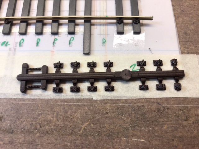 These are the new sprues, 10 standard chairs, 2 bridge , standard chairs and fishplates 982_300507_460000000.jpg 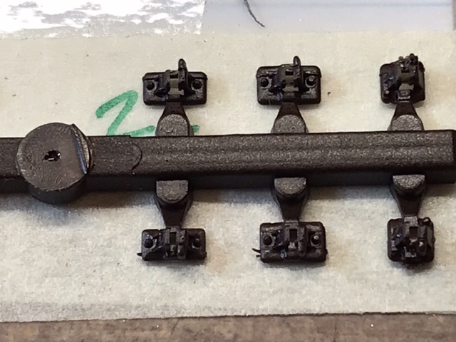 From Left to right standard, J then bridge chairs. The later two have never been available in 2 bolt GWR versions 982_300509_460000000.jpg 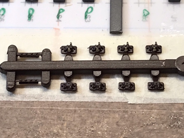 Closer view of the other part of the sprue 982_300510_360000000.jpg 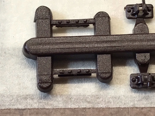 Close up of the H section fishplates, these are available separately in both plastic and brass |
||
|
posted: 30 Oct 2020 21:19 from: Rob Manchester
click the date to link to this post click member name to view archived images |
Hi Matt, Sounds like good fun along the way - thanks for the info. Pity we can't have a compromise on modern cars - rustproof bodies and mechanical/electrical parts that can be fixed at home. I have lost track of the number of cars I have fixed for fiends and neighbours over the years - the last one I can remember was a LR Defender that wouldn't crank over on the starter - just needed a new 12v feed wire to the starter relay and back in business. I have had new/nearly new cars for around 12 years now after I got fed up of spending every other weekend repairing things that had rusted of broken. Meanwhile back to Yeovil ( sorry Andrew....) Rob |
||
|
posted: 31 Oct 2020 06:39 from: Andrew Duncan
click the date to link to this post click member name to view archived images |
Matt M. wrote: HI Andrew,Yup so have I and I dont think its finished yet ....Andrew |
||
|
posted: 31 Oct 2020 06:49 from: Andrew Barrowman
click the date to link to this post click member name to view archived images |
Good grief! You're up early |
||
|
posted: 31 Oct 2020 07:36 from: Andrew Duncan
click the date to link to this post click member name to view archived images |
Andrew Barrowman wrote: Good grief! You're up earlyHello Andy Yup the price I pay, from time to time, of running my own business. At present rather than just worry or concern its more finding the time to do everything that needs to be done. We are in the throws of moving our stock control system (EPOS) to a new provider after 21 years, and the new system goes a long way towards being an ERM system that will be pretty slick once settled in I believe, but is taking an enormous amount of effort and time to train everyone on it. So I woke up early thinking I'd get some stuff done, and I have....catching up on the re-awoken Yeovil thread. Very enjoyable Andrew |
||
|
posted: 31 Oct 2020 09:21 from: Hayfield
click the date to link to this post click member name to view archived images |
With all the things going on at the moment its nice to have a diversion. | ||
|
posted: 3 Nov 2020 22:16 from: Andrew Duncan
click the date to link to this post click member name to view archived images |
Hayfield wrote: With all the things going on at the moment its nice to have a diversion.Hello John Yup agreed, and thanks or the pictures of the all the new lines from C&L. I take it these are extra sprues not replacing the parts being available separately as they have always been...? Kind regards Andrew |
||
|
posted: 3 Nov 2020 22:29 from: Andrew Duncan
click the date to link to this post click member name to view archived images |
Matt M. wrote: Hello Matt Some very nice reminiscences here, and talking of 125's I recall that at the lock up garages where my parents kept their car (remote from the house which wasn't accessible by road) there was a chap who just took delivery of a brand new Fiat 125 and it got to 60mph a couple of seconds ahead of our Volvo Amazon 122S....I was very jealous. but at least the Volvo saw off the Triumph and Rover 2000s with comparative ease! Great memories! Andrew |
||
|
posted: 3 Nov 2020 22:34 from: Andrew Duncan
click the date to link to this post click member name to view archived images |
Rob Manchester wrote: Hi Matt,No apology necessary Rob. I think everyone's thoroughly enjoying the memories and nostalgia. I'm certainly doing so... Kind regards Andrew Edit Here is the rather sad day that I said goodbye to my 1962 MGA Deluxe... 2787_031754_420000000.jpg  Not looking terribly happy but the tyres managed to stay inflated for 25 years without use! Apparently the engine started first time when they tried as well. Gone to a good home. Andrew |
||
| Last edited on 3 Nov 2020 22:58 by Andrew Duncan |
|||
|
posted: 3 Nov 2020 22:43 from: Andrew Barrowman
click the date to link to this post click member name to view archived images |
My dad had a 125S and I used to take it for a spin. I never actually pranged it. We were less than impressed with the local Fiat place. They failed to replace one of the four big bolts that attached the bell-housing to the engine when they renewed the clutch. Fortunately I happened to notice it before there was any damage. I was also less than impressed by my Volvo dealer in California. They left one of the wheel bolts out when they gave my brand new XC70 its first service! | ||
|
posted: 3 Nov 2020 23:33 from: Andrew Duncan
click the date to link to this post click member name to view archived images |
John Lewis wrote: Rob Manchester wrote:Very witty chaps...!😊AndrewMatt M. wrote:PS I have enjoyed the car diversion.Back on track then.... |
||
|
posted: 3 Nov 2020 23:50 from: Andrew Duncan
click the date to link to this post click member name to view archived images |
Andrew Barrowman wrote: My dad had a 125S and I used to take it for a spin. I never actually pranged it. We were less than impressed with the local Fiat place. They failed to replace one of the four big bolts that attached the bell-housing to the engine when they renewed the clutch. Fortunately I happened to notice it before there was any damage. I was also less than impressed by my Volvo dealer in California. They left one of the wheel bolts out when they gave my brand new XC70 its first service!Hello Andy At work we have a saying / rule “ that mistakes are our friends” in other words a learning opportunity. I suppose there are some instances in life when that might be a bit too liberal an attitude. Not sure about bell housings, but wheel bolts and high voltages come to mind, when I think it might be too late to be friendly! Glad you spotted both before it ended in tears. Andrew |
||
|
posted: 4 Nov 2020 00:14 from: Rob Manchester
click the date to link to this post click member name to view archived images |
Andrew Barrowman wrote: My dad had a 125S and I used to take it for a spin. I never actually pranged it. We were less than impressed with the local Fiat place. They failed to replace one of the four big bolts that attached the bell-housing to the engine when they renewed the clutch. Fortunately I happened to notice it before there was any damage. I was also less than impressed by my Volvo dealer in California. They left one of the wheel bolts out when they gave my brand new XC70 its first service! Funny that - just been watching reviews etc on the XC70. Nice cars Volvo's - had a 940 saloon back in the 1990's and it was so comfortable. When we got the Subaru Outback a few years back I had to convince my wife that it was a long term purchase and it did everything I wanted ( fishing, camps, beaches, holidays etc ) which indeed it does. She may just kill me if she catches a glance at my browsing history My worst garage job was when I had a Merc 190 estate. Took it in for a clutch replacement, picked it up and it worked great for a week until the gearbox linkage fell apart due to the bits they forgot to put back.... Rob |
||
| Last edited on 4 Nov 2020 01:18 by Rob Manchester |
|||
|
posted: 4 Nov 2020 00:59 from: Andrew Barrowman
click the date to link to this post click member name to view archived images |
Hi Rob, The MPG number is likely legit. My wife had a VW Jetta Turbodiesel and it did 50 MPG on a 50 mile journey, and that's US gallons. Unfortunately VW were cheating the emissions test, they got caught and the guvmint made them pay out a lot of money to the buyers or buy them back. It was such a good deal we gave it back. Its dual clutch automatic was brilliant too. But we are giving Andrew an excuse for not getting on with his layout! Maybe we should start a Car Talk thread? Andy |
||
|
posted: 4 Nov 2020 01:08 from: Andrew Barrowman
click the date to link to this post click member name to view archived images |
Andrew, The bell-housing is the fat bit on the end of the gearbox/transmission where the clutch/torque-converter lives. Under heavy load the missing bolt could have wrecked the transmission and the engine crankcase. Ouch! Andy |
||
|
posted: 4 Nov 2020 01:14 from: Andrew Duncan
click the date to link to this post click member name to view archived images |
Just in case you’re beginning to rue the day I mentioned Alpina, here is reminder of what this thread used to be about. Over the weekend I got fed up with looking at the layout in it’s sorry half taken apart state and temporarily reinstalled some of the scenery, platform, bridge and cattle dock and took snap to prove to myself, probably more than anyone, that I had made some really good progress earlier in the year. Found it quite encouraging! 2787_032012_420000000.jpg 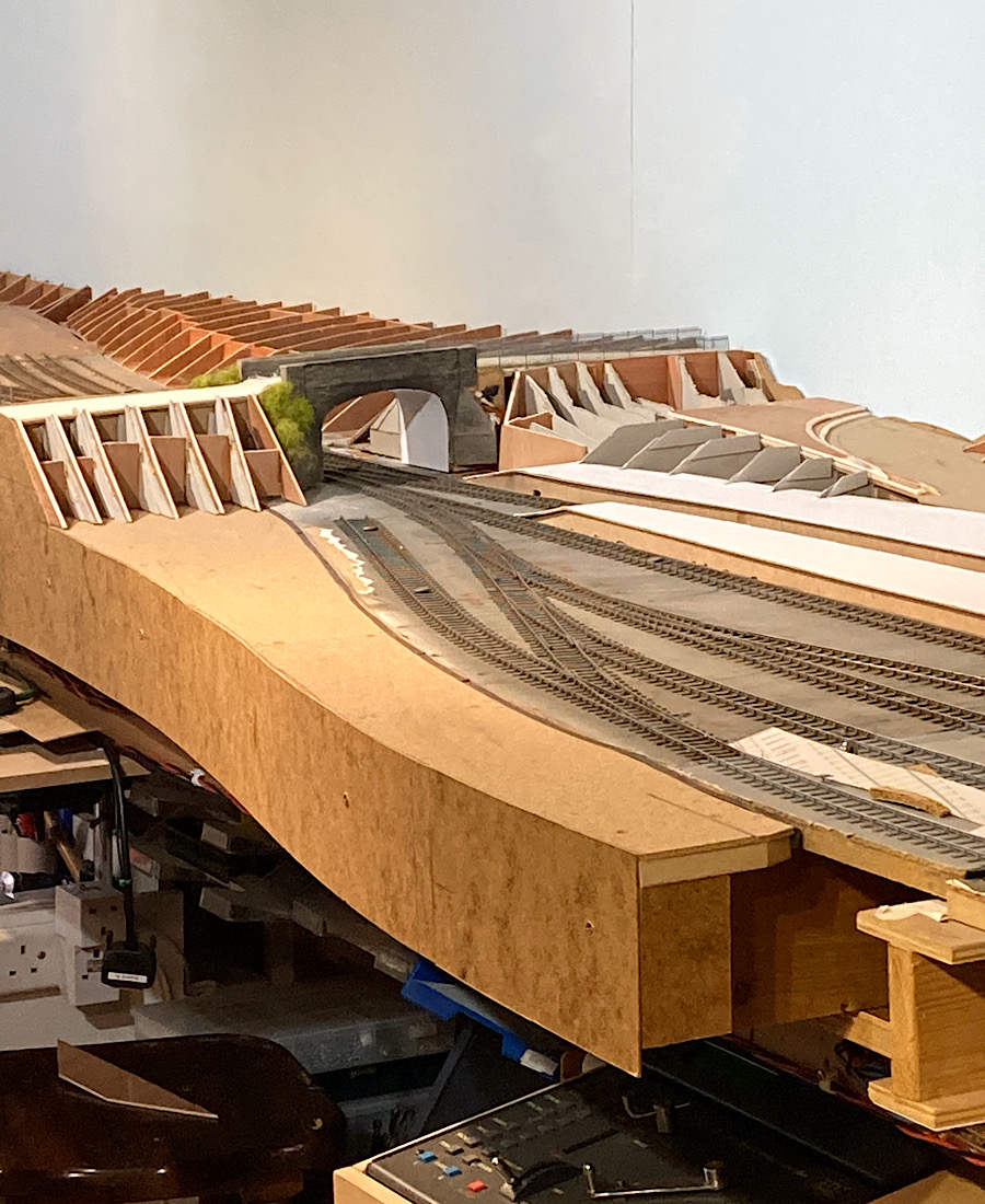 |
||
|
posted: 4 Nov 2020 01:22 from: Rob Manchester
click the date to link to this post click member name to view archived images |
Andrew, Ah, back to railways. I have just been doing a stock check of my track making parts. For some reason I have over 6,500 Pandrol flat bottom baseplates - can't think what I got all those for The picture of the bridge looks good, can't wait to see some more progress when you can get around to it. Rob |
||
|
posted: 4 Nov 2020 09:26 from: Hayfield
click the date to link to this post click member name to view archived images |
Andrew Duncan wrote: Hayfield wrote:AndrewWith all the things going on at the moment its nice to have a diversion.Hello John These will be the standard sprues, you get 350 items per pack rather than 250, therefore the packs are priced accordingly. The thing to remember is that the cost will be about neutral if you build turnouts, I do seem to get through quite a lot of bridge chairs and if I had J chairs this would also be similar, plus I am a bib fan of these fishplates. In the past when C&L sold the Exactoscale special chairs, these were dearer than normal chairs For me it will get more folk thinking about what chair goes where rather than chopping up standard chairs. Phil is in the process of thinking about have a range of knuckle, elbow chairs and crossing nose chairs, It will be a universal style where items are cut to length. But a long way off and may not be feasible. I still find the Exactoscale switch, check, slip and obtuse chairs cover most aspects |
||
|
posted: 23 Nov 2020 00:51 from: Andrew Duncan
click the date to link to this post click member name to view archived images |
Hello John Sorry for the late reply and thank you for the various explanations of the logic behind the changes Here’s a small update of a bit of progress on the line under the station. This is the copper paxolin rail support for the doorway bridge. This where trains leap into the air... For some understanding of what I’m saying keep going.... 2787_221930_560000000.jpg 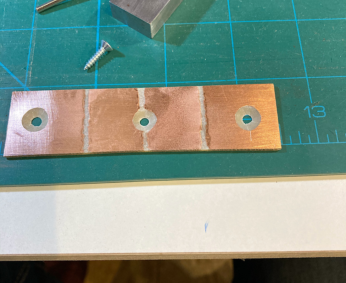 And here it is installed in place on the end of the track bed already gapped ready to accept the rails that will be soldered to the copper 2787_221935_530000000.jpg 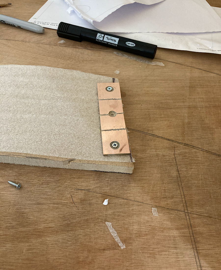 And here we are looking at the “precipice” with some track just laid in place to give the idea of what I’m doing or rather trying to do. 2787_221937_410000000.jpg 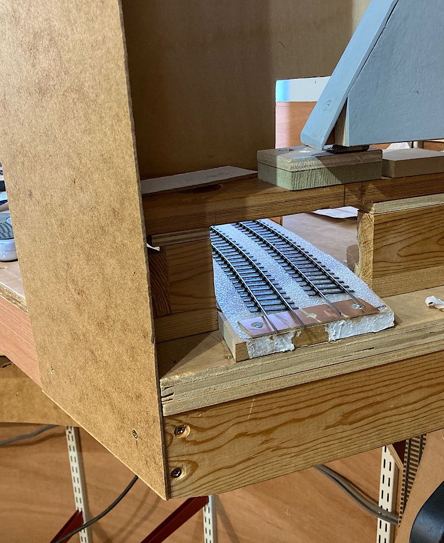 That’s it for tonight. Kind regards Andrew |
||
|
posted: 23 Nov 2020 06:04 from: Andrew Barrowman
click the date to link to this post click member name to view archived images |
Hi Andrew, I have done something similar and I also soldered brass tubes to the copper that accepted pieces of 1/8" diameter piano wire. They were inserted into the tubes to keep the rail aligned when the bridge was closed. Cheers! Andy |
||
|
posted: 23 Nov 2020 11:26 from: Phil O
click the date to link to this post click member name to view archived images |
Hi Andrew, Something which may be of use to you, is to feed the tracks either side of the bridge from the bridge section, so that trains cannot take a nose dive if the bridge is out, ideally at least a foot either side of the gap. Cheers Phil. |
||
|
posted: 23 Nov 2020 12:28 from: Martin Wynne
click the date to link to this post click member name to view archived images |
Another idea is the weighted flap on the end of the fixed board, which is pushed down when the bridge is dropped in place: 2_230723_390000000.jpg  My graphics skills well in evidence there. Martin. |
||
|
posted: 23 Nov 2020 18:25 from: Phil O
click the date to link to this post click member name to view archived images |
Martin, I think Andrew would struggle to open the bridge with a 5 ton weight, assuming that the baseboard could take the weight, could it be an ACME weight? As per the Whiley Coyote and Roadrunner. 😄😄 Phil. |
||
|
posted: 23 Nov 2020 20:41 from: Andrew Duncan
click the date to link to this post click member name to view archived images |
Andrew Barrowman wrote: Hi Andrew, Hello Andy Yup good idea, and in fact I used the same approach when I had a lift type of fiddleyard, an Iain Rice design, although not perhaps one of his greatest. It certainly needed a means of keeping the different levels aligned, and quite some strength and sense of balance to achieve a smooth transition from one level to the next. In this instances however I think I'm going to rely a simple swing bridge with an adjustable stop(for lateral rail alignment), and with the far, unsupported end of the bridge, held by a lip to keep the vertical levels correct. Not elegant but quite functionally effective. Having said that, it looks as though Martin and Phil have other ideas....? Kind regards Andrew |
||
|
posted: 23 Nov 2020 23:35 from: Nigel Brown click the date to link to this post click member name to view archived images |
Best of luck, Andrew. I hate moveable track over gaps, from past experience. It's so easy for the gap to change... Nigel |
||
|
posted: 24 Nov 2020 03:12 from: Andrew Duncan
click the date to link to this post click member name to view archived images |
Martin Wynne wrote: Another idea is the weighted flap on the end of the fixed board, which is pushed down when the bridge is dropped in place: Hello Martin Your graphic looks interesting but I’m not sure I follow it. Does the weight flip the bridge deck up into place that would otherwise be hanging down vertically? Or have I got completely the wrong end of the stick Kind regards Andrew |
||
|
posted: 24 Nov 2020 03:31 from: Andrew Duncan
click the date to link to this post click member name to view archived images |
Phil O wrote: Martin,Hello Phil I’m afraid I’m not familiar with the Whiley Coyote, Roadrunner story, but yes a dead section either side of the bridge is going to be essential. Like your idea of feeding it from the bridge power. On my old Maiden Newton layout I had dead sections controlled by a couple of microswitches. Your idea will only require one switch per power district ( one UP, and one DOWN). Neat. Kind regards Andrew |
||
|
posted: 24 Nov 2020 03:45 from: Andrew Duncan
click the date to link to this post click member name to view archived images |
Nigel Brown wrote: Best of luck, Andrew. I hate moveable track over gaps, from past experience. It's so easy for the gap to change...Hello Nigel Yes I know what you mean, however one of the great advantages of 00 and EM is the slop that allows a certain forgiveness that I understand / imagine P4 doesn’t. Don’t know how 3mm does in this regard, but it must be harder? In the next few days I’ll take a photo of what I have in mind. Kind regards Andrew |
||
|
posted: 24 Nov 2020 04:01 from: Andrew Barrowman
click the date to link to this post click member name to view archived images |
Phil O wrote: Martin,Objection! It's Wiley (which, as it happens, is one of my middle names). |
||
|
posted: 24 Nov 2020 08:11 from: Martin Wynne
click the date to link to this post click member name to view archived images |
Andrew Duncan wrote: Martin Wynne wrote:Hi Andrew, You've got the wrong end of the stick, sorry I failed to make a proper drawing. It's not about how to make the bridge itself work, I assumed you have got that decided. It's a safety device in response to Phil's suggestion about preventing trains falling off the layout when the bridge is not present. The flap is a vertical piece of hardboard or somesuch, attached to the end face of the fixed baseboard on a pivot (loose screw/washer). When the bridge is removed, the flap flips up and physically blocks the end of the tracks. When the bridge is dropped into place, the flap gets pushed down out of the way. The flap needs a small block of wood or whatever attached to it as a pusher-downer, which I omitted to draw. The top black blob is another screw or whatever to act as a stop in the up position. You could use any sort of removable end plate on the baseboard, but the idea of the pivoted flap is that you can't forget to put it in place. Instead of the weight you could use a spring. But gravity is free, never breaks, and unlike a spring exerts a constant force. p.s. I have just realised you intend a horizontal swing bridge, rather than a lifting bridge. Which means a bit of a design change on the flap, so that it can swing sideways out of the way. Or alternatively holding it down manually while you swing the bridge into position. cheers, Martin. |
||
|
posted: 24 Nov 2020 09:02 from: Phil O
click the date to link to this post click member name to view archived images |
Andrew Duncan wrote: Phil O wrote:Hi Andrew,Martin,Hello Phil Here's a link to one, there are a few on Youtube, if you want to waste a few hours. http://www.youtube.com/watch?v=GdKkI1vGsmE Part of my misspent child/adulthood. Phil. |
||
|
posted: 24 Nov 2020 16:25 from: Tony W
click the date to link to this post click member name to view archived images |
Andrew Duncan wrote: Nigel Brown wrote:Best of luck, Andrew. I hate moveable track over gaps, from past experience. It's so easy for the gap to change...Hello Nigel Hi Andrew. This is an issue I have to face with my layout and the lifting flap / removable sections. I think you are correct that P4 tolerances are less forgiving of baseboard joint misalignment than OO and EM standards. One of the reasons for my using high quality pattern makers dowels to ensure consistent mating at the joints. I also have the issue of making sure a goodly length of track either side of the lifting flap is isolated when the draw bridge is up and there are several tracks involved at the lifting flap. Regards Tony. |
||
| Last edited on 24 Nov 2020 16:28 by Tony W |
|||
|
posted: 24 Nov 2020 23:35 from: Andrew Duncan
click the date to link to this post click member name to view archived images |
Phil O wrote: Andrew Duncan wrote:Hello Phil,Phil O wrote:Hi Andrew,Martin,Hello Phil I am now educated...and after only 7 minutes. Wish my lessons at school had been this length....! Andrew |
||
|
posted: 24 Nov 2020 23:43 from: Andrew Duncan
click the date to link to this post click member name to view archived images |
Martin Wynne wrote: Andrew Duncan wrote:Aaaah I see what you mean now Martin. Thank you.Martin Wynne wrote:Hi Andrew, Kind regards Andrew |
||
|
posted: 29 Nov 2020 22:28 from: Andrew Duncan
click the date to link to this post click member name to view archived images |
Tony W wrote: Andrew Duncan wrote:Hello TonyNigel Brown wrote:Best of luck, Andrew. I hate moveable track over gaps, from past experience. It's so easy for the gap to change...Hello Nigel Sorry to take so long to reply. Yes it sounds like you have a bit of a challenge on your hands, but it seems from my observations of your work, that you seem to delight in such things and you do it all in S4 to boot! I've made a little progress today and over the weekend, which is gradually restoring my modelling spirit and enthusiasm for railway modelling and Yeovil Pen Mill in particular, which I hope you'll agree is a good thing. Kind regards Andrew If I can, I'll post some pictures shortly. Edit And here are a few... Here is the first join in the C&L flexi track after the swing bridge. So to isolate the power to the right section of track in the picture from its district power supply, I’ve used copper paxolin sheet, gapped in a “cross” to produce a strong mechanical join, but also keeps all 4 rails electrically separate. A bit crude but quite effective I hope. Incidentally, I don’t recall whether I mentioned this before, but I gapped it with a Dremel / abrasive stone which I feel is better than a file or saw as it gives a wider gap( more reliable isolation?) and less likely to weaken the paxolin, and its quicker! All tested with a metre to check lack of electrical integrity. 2787_292330_500000000.jpg 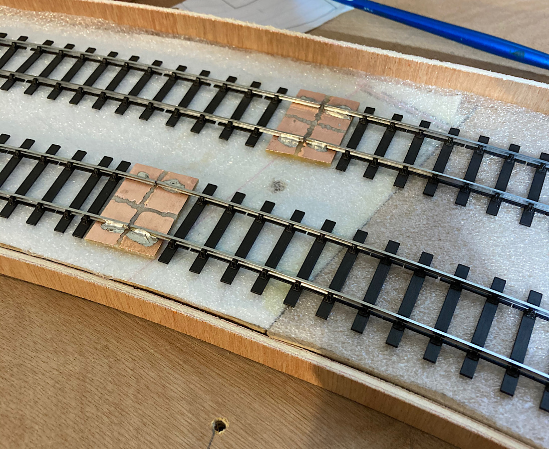 Sorry about the picture, it came out sideways. Martin if you felt like it, would you mind turning it round? Cleaning up the joint with a brush loaded with a water meths mix kill the flux residues. 2787_292353_150000000.jpg 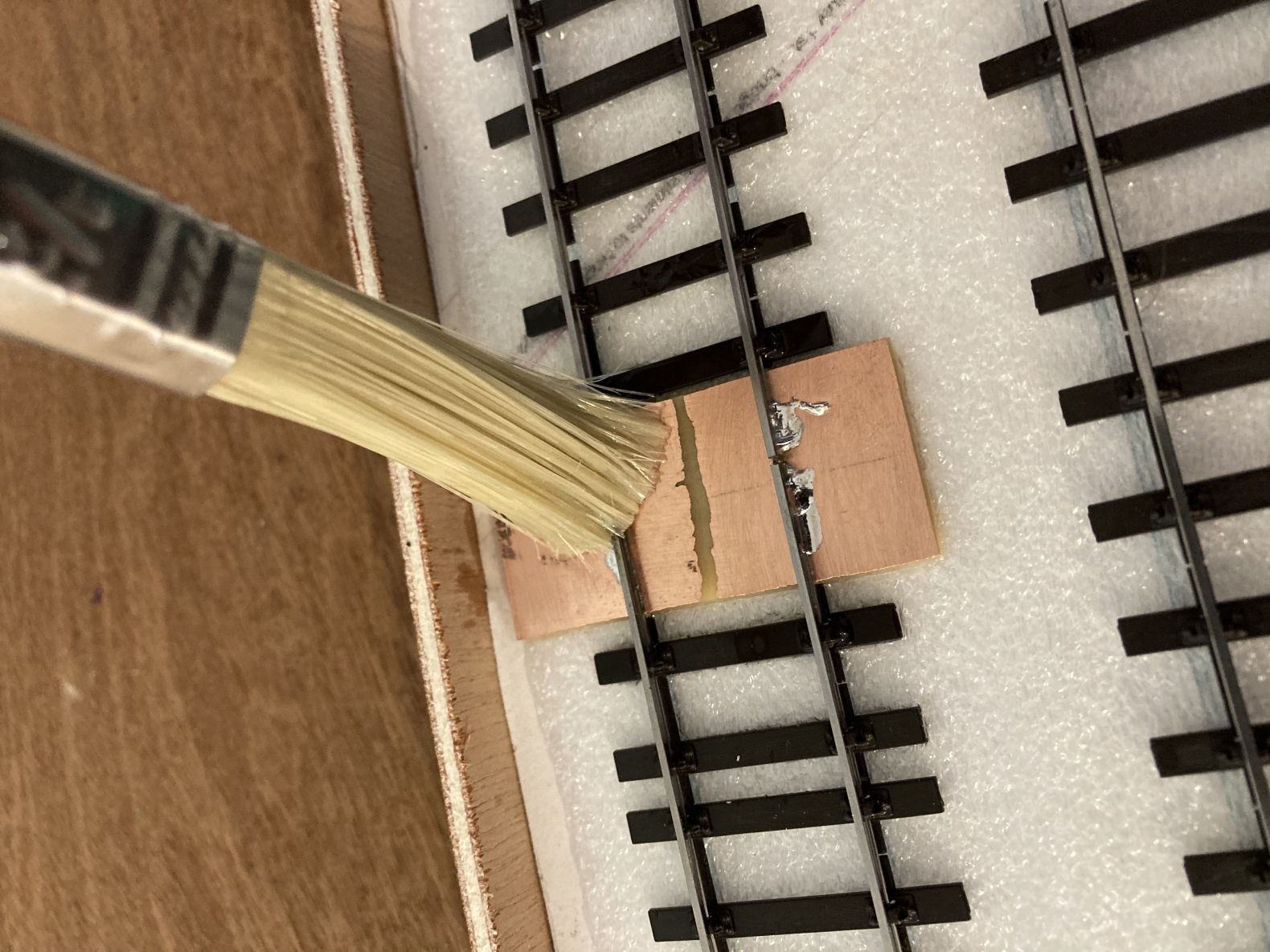 Mirror alignment checks 2787_292359_400000000.jpg 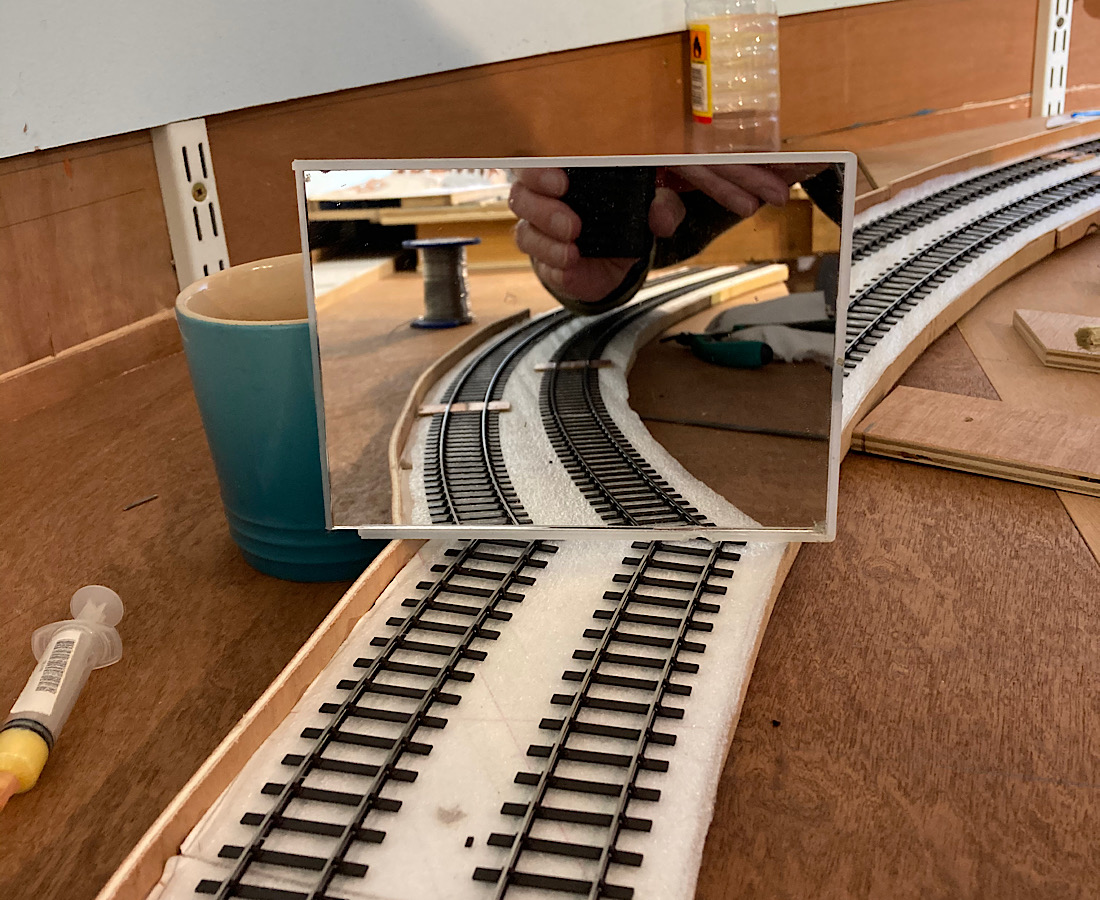 Checking the alignment of the curve with a mirror during the soldering operation. Why does this work so well in identifying poor alignment....? An overview of my progress this weekend. The two lengths disappearing underneath the station are just laid in place for the photo and to double check clearances above. 2787_300006_120000000.jpg 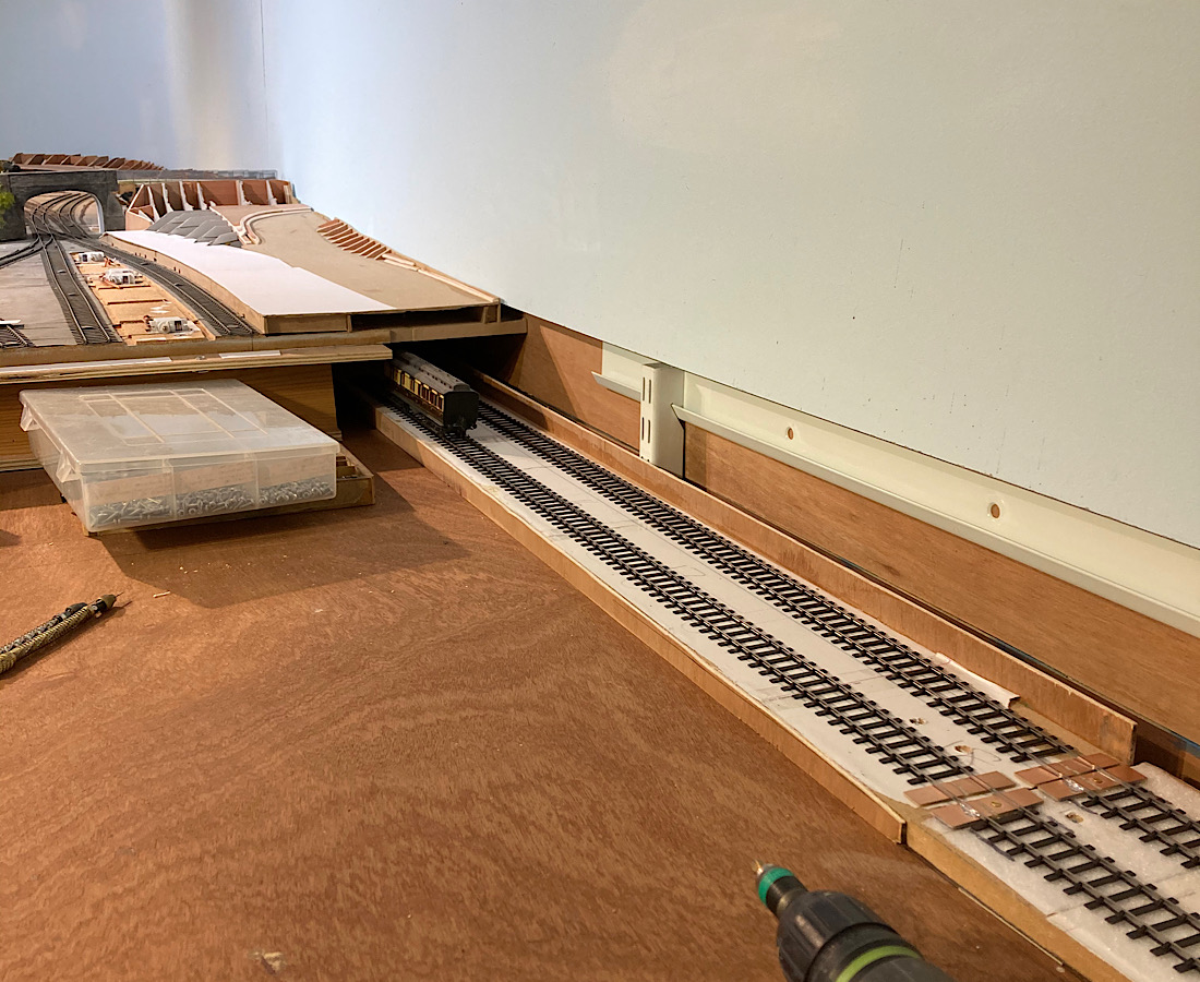 That’s about it for now. Kind regards Andrew |
||
| Last edited on 30 Nov 2020 05:16 by Andrew Duncan |
|||
|
posted: 30 Nov 2020 10:39 from: Tony W
click the date to link to this post click member name to view archived images |
Hi Andrew. Delight isn't quite how I would describe my approach to the situation. It sort of comes with the territory and one just has to accept it as part of the challenge. Good to see that you are finding renewed enthusiasm for modelling again. Looking at your pictures, I hope you are not attempting to fix long lengths of track rigidly at both ends or one of two things will happen. Either the soldered joints at at least one end will fracture or the middle of the section will buckle with the effects of expansion / contraction. This was one of the problems with the track on some of the second hand baseboards I acquired for my layout. Allowances for this need to be made somewhere. Regards Tony. |
||
|
posted: 30 Nov 2020 20:58 from: Rob Manchester
click the date to link to this post click member name to view archived images |
Hi Andrew, Thanks for posting the pictures, look good as usual. My view on the mirror trick is that it just enables you a way to get a view round the curves from a sensible viewing position without contorting(?) the body into unusual positions - thats my view anyway. Tony is right about the long lengths of 'captive' track. I helped repair a similar issue on a friend's layout last year. He had several lengths of track made from uncut yard lengths of rail leading to the fiddle yard made with Exactoscale track bases and BH rail and he had soldered each rail length together. He then pinned the lot down. No prizes for guessing what happened over the winter in his cold shed Keep up the good work. Rob |
||
|
posted: 30 Nov 2020 21:41 from: Nigel Brown click the date to link to this post click member name to view archived images |
I never bother with rail joiners. I just leave a slight gap between each rail length, and take care when laying to have them aligned. I use a dropper from each piece of rail for electrical continuity. Haven't had a problem yet. Nigel |
||
|
posted: 30 Nov 2020 21:50 from: Tony W
click the date to link to this post click member name to view archived images |
Hi Nigel. I use a similar system except that I use a minimum of two droppers per rail length and limit the rail lengths to about a scale 60ft. I will be adding scale fishplates to the scenic track later for cosmetic reasons. I have had the odd gap close in very hot weather, but it is rare. Regards Tony. |
||
|
posted: 30 Nov 2020 22:05 from: Nigel Brown click the date to link to this post click member name to view archived images |
Tony W wrote: Hi Nigel. Hi Tony Keeping things not too long makes sense. This is 3mm Society code 60 BH rail which comes in 18" lengths, so it's not that long anyway. Cheers Nigel |
||
|
posted: 30 Nov 2020 22:29 from: Andrew Duncan
click the date to link to this post click member name to view archived images |
Tony W wrote: Hi Andrew. Hello Tony Thanks for the reminder I was about to do just that, (worrying how much I can forget over time) so I'll need to put a fish-plated joint in at the other end and see how that fares. If that isnt sufficient I'll make another break half way along.... Kind regards Andrew |
||
|
posted: 30 Nov 2020 22:57 from: Tony W
click the date to link to this post click member name to view archived images |
Hi Andrew. If you have already soldered both ends, it may just be easier to cut the sections in the middle and use rail joiners. After all that section is going to be hidden anyway. Electrically it will be the same. Regards Tony. |
||
|
posted: 1 Dec 2020 04:11 from: Andrew Barrowman
click the date to link to this post click member name to view archived images |
Hi Andrew, I think the mirror trick works because you can see the track effectively at twice the viewing distance. Without the mirror you might well have to remove a wall It's not only the rail that expands and contracts. Wood alters its dimensions quite a bit too, but more in response to changes in relative humidity than temperature. We became acutely aware of this phenomenon when we moved furniture and my layout from Paisley (very high RH) to Mesa, Arizona (very low RH). Most of the furniture fell to bits Andy |
||
|
posted: 1 Dec 2020 07:02 from: Andrew Duncan
click the date to link to this post click member name to view archived images |
Tony W wrote: Hi Andrew.Hello Tony No the end near the station isn’t finished properly, but I am making the curved section a separate board to the straight section( that goes under the station in the photo) so I’ll need to use a fishplate soldered to the copper paxolin to allow movement, not to connect to the next board, just to align. I’mprobably unclear, so I’ll take a picture when I’ve done it. Thanks again for mentioning it. Andrew |
||
|
posted: 2 Dec 2020 05:18 from: Andrew Duncan
click the date to link to this post click member name to view archived images |
Rob Manchester wrote: Hi Andrew,Hello Rob I must say your view of why the mirror shows up irregularities more than staring at the track directly, is a very simple one. A bit disappointing really as I thought you, and / or other educated chaps frequenting this forum, would be wielding words such as parallax or with your photographic background be quoting refractions of light, or perhaps sine, cosine, tangents and all those other things that completely passed me by at school. But no it’s a contortion avoider,,,very likely....? This is beginning to sound like “Call my Bluff” ( Robert Robinson, Frank Muir Dennis Norden et al, from the late 60’s or was it 70’s?) so I’d better stop this fantasy before the men in white coats come and whisk me away. Thanks for your encouragement, always welcome. Kind regards Andrew |
||
|
posted: 2 Dec 2020 10:00 from: Charles Orr
click the date to link to this post click member name to view archived images |
Norman Solomon always advised the use of a mirror to check for kinks and alignment issues when building track. | ||
|
posted: 2 Dec 2020 16:43 from: Rob Manchester
click the date to link to this post click member name to view archived images |
Hi Andrew, I never did wear a bow tie like the names from the past you mentioned - maybe if I had I could have come up with some grander explanation for the mirror Rob |
||
|
posted: 2 Dec 2020 22:52 from: Andrew Duncan
click the date to link to this post click member name to view archived images |
Andrew Barrowman wrote: Hi Andrew,Hello Andy Aaah now this is beginning to get interesting. A wall remover avoiding aid. Unusual. And on a slightly more serious note, doubling the viewing distance is possibly beginning to make sense, And so far as wood is concerned, yes I agree, itis surprisingly unstable when we are measuring everything in millimetres and even parts of a millimetre. I painted all my baseboards in an attempt to prevent moisture getting in, but I still get gaps appearing at different times of the year between one of flaps that crosses the door way and its opposite side. I suppose if it bothers me, i.e.the trains fall off the track, then I’ll do something about it. Maybe use one of the baseboard alignment dowels vertically mounted to pull the parts into closer alignment. Goodnight for now. Andrew |
||
|
posted: 2 Dec 2020 23:08 from: Andrew Duncan
click the date to link to this post click member name to view archived images |
Rob Manchester wrote: Hi Andrew, I wonder if Andy is a bow tie wearer? No offence Rob, but he has come up with the most technical possibility so far in “ doubling the distance”. Not sure he’s right, but it sounds like someone has put some thought into it doesn’t it? Not quite so convinced by the wall removal avoidance, though. I think we probably need Frank Muir.... Andrew Andrew |
||
|
posted: 2 Dec 2020 23:34 from: Rob Manchester
click the date to link to this post click member name to view archived images |
Andrew, Ah but, his explanation would mean me taking off my +2.5 glasses and using something less strong if the viewing distance is doubled And anyway the two mirrors I have to hand are very old and shaving in the bath with the mirror on your knees takes its toll of the coating so they aren't too clear anymore......sorry if that is an image you would rather me not have painted Rob |
||
|
posted: 3 Dec 2020 07:10 from: Andrew Barrowman
click the date to link to this post click member name to view archived images |
Andrew Duncan wrote: Rob Manchester wrote:Hi Andrew, Hi Andrew, I do have a bow tie, but it's only suitable for wearing with a monkey suit. I suspect you are thinking of one that would be more appropriate with a Harris Tweed sports jacket. I have one of those too but I only wear it when I'm zipping around in the Fiat with the lid down In the past I was employed in academia, but only as a humble technician in a couple of great Uni's in Glasgow. I was really fortunate because I learned so much from some truly brilliant people. Prior to that I did work for a company that made high resolution optical displacement traducers and the people there were great teachers too. The last time I had occasion to don the monkey suit was, believe it or not, for an encounter with Maggie Thatcher in California. My boss dumped it on me although I did think it would have been very interesting. Unfortunately Mrs Thatcher went into decline around that time and could not make it. Somewhere there is a photo of me (in monkey suit) with my lovely Lorna posed beside Jim Baker who was substituted for Ms Thatcher. These days I'm more likely to wear my kilt for formal occasions. Gunn tartan, but that's probably a bit too much information. A good example of the greater distance trick is telephoto shots of approaching trains at some distance. The track usually looks like spaghetti Cheers! Andy PS Keep plugging away! |
||
|
posted: 3 Dec 2020 09:11 from: Alan Banks
click the date to link to this post click member name to view archived images |
Charles Orr wrote: Norman Solomon always advised the use of a mirror to check for kinks and alignment issues when building track.He obviously didn't wear Varifocals. Trying to get track straight with them on is virtually impossible. Track can curve both ways depending on a slight movement of one's head! Grrr! Alan |
||
|
posted: 3 Dec 2020 19:34 from: Andrew Duncan
click the date to link to this post click member name to view archived images |
Rob Manchester wrote: Andrew, Rob Yes well this didn't do much for the techie side that I was hoping for but on the other hand it had me in stitches, which only goes to prove you don't necessarily get what want in life, but do get what you need... (very) good one Rob Andrew |
||
|
posted: 4 Dec 2020 20:12 from: Andrew Duncan
click the date to link to this post click member name to view archived images |
Hello Andy My answers are in your text. Kind regards Andrew Andrew Barrowman wrote: Hi Andrew, |
||
|
posted: 4 Dec 2020 20:20 from: Andrew Duncan
click the date to link to this post click member name to view archived images |
Alan Banks wrote: Charles Orr wrote:Hello Charles and AlanNorman Solomon always advised the use of a mirror to check for kinks and alignment issues when building track.He obviously didn't wear Varifocals. Trying to get track straight with them on is virtually impossible. Track can curve both ways depending on a slight movement of one's head! Grrr! I never did get used to Varifocals, gave up and went to bifocals instead, which I can vouch for in this context. Is it worth investing in a pair just to do track making with....a moot point? Kind regards Andrew |
||
|
posted: 5 Dec 2020 01:26 from: Andrew Barrowman
click the date to link to this post click member name to view archived images |
Hi Andrew, So far I've only been able to find this one. It is a couple of years old. Andy 2983_042024_170000000.jpg  |
||
|
posted: 6 Dec 2020 22:13 from: Andrew Duncan
click the date to link to this post click member name to view archived images |
Andrew Barrowman wrote: Hi Andrew,Hi Andy Lovely photo, very romantic, a ride through the snow. and a tractor with chains on its wheels! Now thats one upmanship! Not sure I'd recognise either of you if we met in the street though...? I managed to do an hour or so's stuff in the shed today and started by replacing the solid soldered connections at each end with loose-ish fishplate connections (that will allow the rail to slide in the fishplate) and began to prepare the route that the wire would take for the power supply to up and down main lines under the station. Going to be a long and hectic day tomorrow as I hope the next two or three weeks of days will be if Christmas trade goes according to plan? So an early night is called for I think. Kind regards Andrew Edit:And here’s a poor photo of one end modification 2787_061736_440000000.jpg 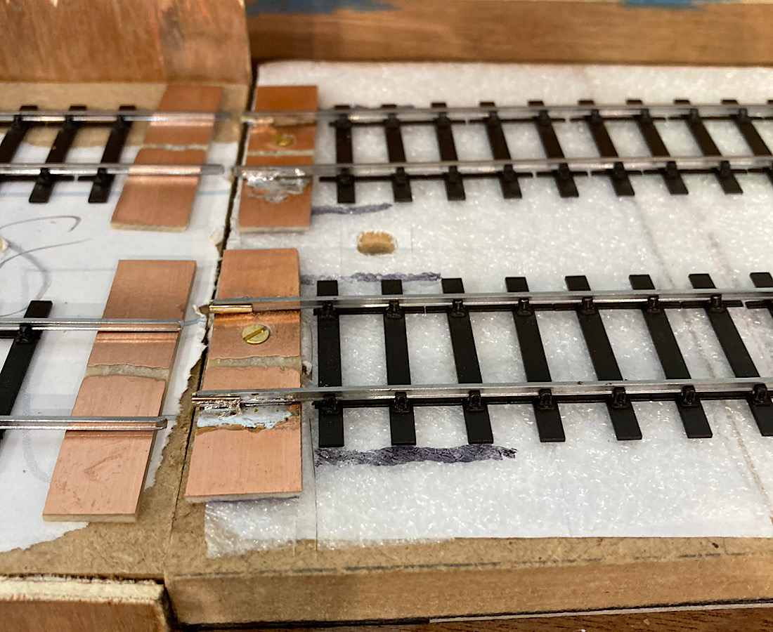 So poor in fact that on my iPad I can’t really see that there are now fishplates keeping the rail in alignment, but they are now there, I assure you Andrew |
||
| Last edited on 6 Dec 2020 22:45 by Andrew Duncan |
|||
|
posted: 7 Dec 2020 15:53 from: Tony W
click the date to link to this post click member name to view archived images |
Hi Andrew. You have also got the problem of trying to cleanly remove the solder from the web of the rail where the joiners go now, which is one reason I suggested cutting them at center. The main thing is that free movement is allowed. Good luck with the Christmas trade by the way. Regards Tony. |
||
|
posted: 7 Dec 2020 22:01 from: Andrew Duncan
click the date to link to this post click member name to view archived images |
Tony W wrote: Hi Andrew.Hello Tony Yup you are quite right of course and I might have made more effort so to do, but the side of me (the 80 side, which can be quite dominant depending on my mood and how many people are looking) that thinks its not going to be on view so as long they slide I'll be ok, RULES! Not particularly proud of it, and I know that you wouldn't cut such corners, but sometimes I just cant help myself or perhaps more accurately cant make myself do the job properly! So keep your fingers crossed that I get away with it. I am I suppose also banking on the temperature variation not being much more than 30 or 40 degrees, mid fifties to mid eighties is my guess. Benefit of 6" of wall insulation and a greenhouse heater? Anyway Tony thank you for your explanation and your thought through approach, which continues to impress me greatly. Kind regards Andrew PS thanks also for your best wishes, much appreciated. |
||
|
posted: 14 Dec 2020 21:06 from: Andrew Duncan
click the date to link to this post click member name to view archived images |
Hello Everyone Here is the result of the weekends work. I've almost finished wiring up the first curved section from the flap crossing the door way into the shed, to the long straight that goes under the station forecourt. Not a lot to show really and all pretty simnple electrically, ie two districts, (distyricts being DCC terminology for seperately fed areas of the layout, making short circuits easier to spot) one for the UP main line amd one for the DOWN Main. Red for the near side rail and black for the far side. 2787_141550_110000000.jpg 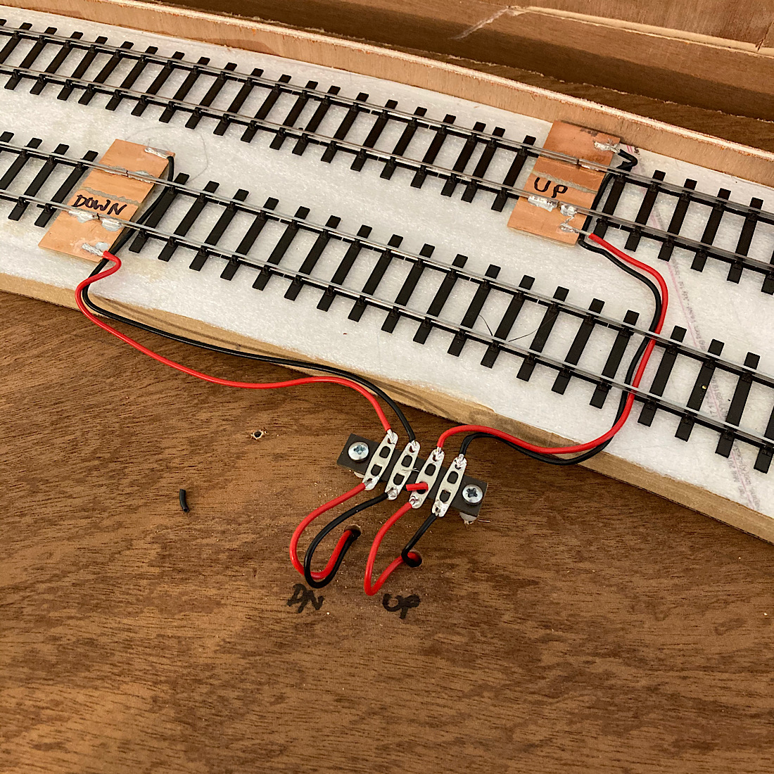 And these disappear through holes in the sub baseboard to emerge through the framing right at the bottom of the photo, to connect to the power bus of which there are 4. One(Pink) for the branch. Two(Blue) for the UP main. Three(Green) for the DOWN Main. Four(Orange) for the marshalling yard in front of the platforms. 2787_141553_340000000.jpg 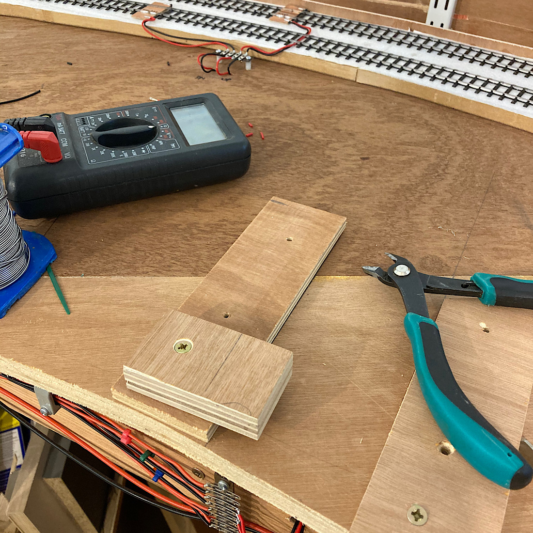 Now to dismantle the layout again as I work my way up the long 1:100 slope under the station forecourt, which requires removing two baseboards at a time to gain access to install the underlay, lay the track, install the wiring. So here goes. Here you see platform one, the Up platform still intact. 2787_141605_550000000.jpg 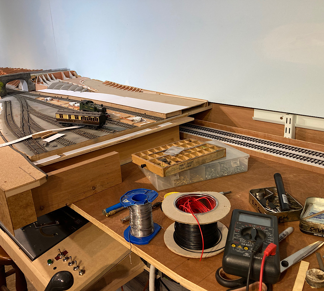 and now you don't... 2787_141555_490000000.jpg 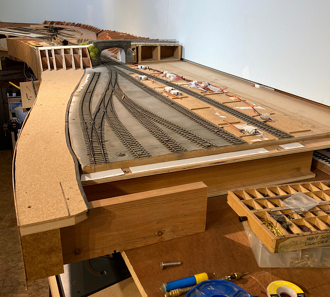 the bridge goes next 2787_141557_490000000.jpg 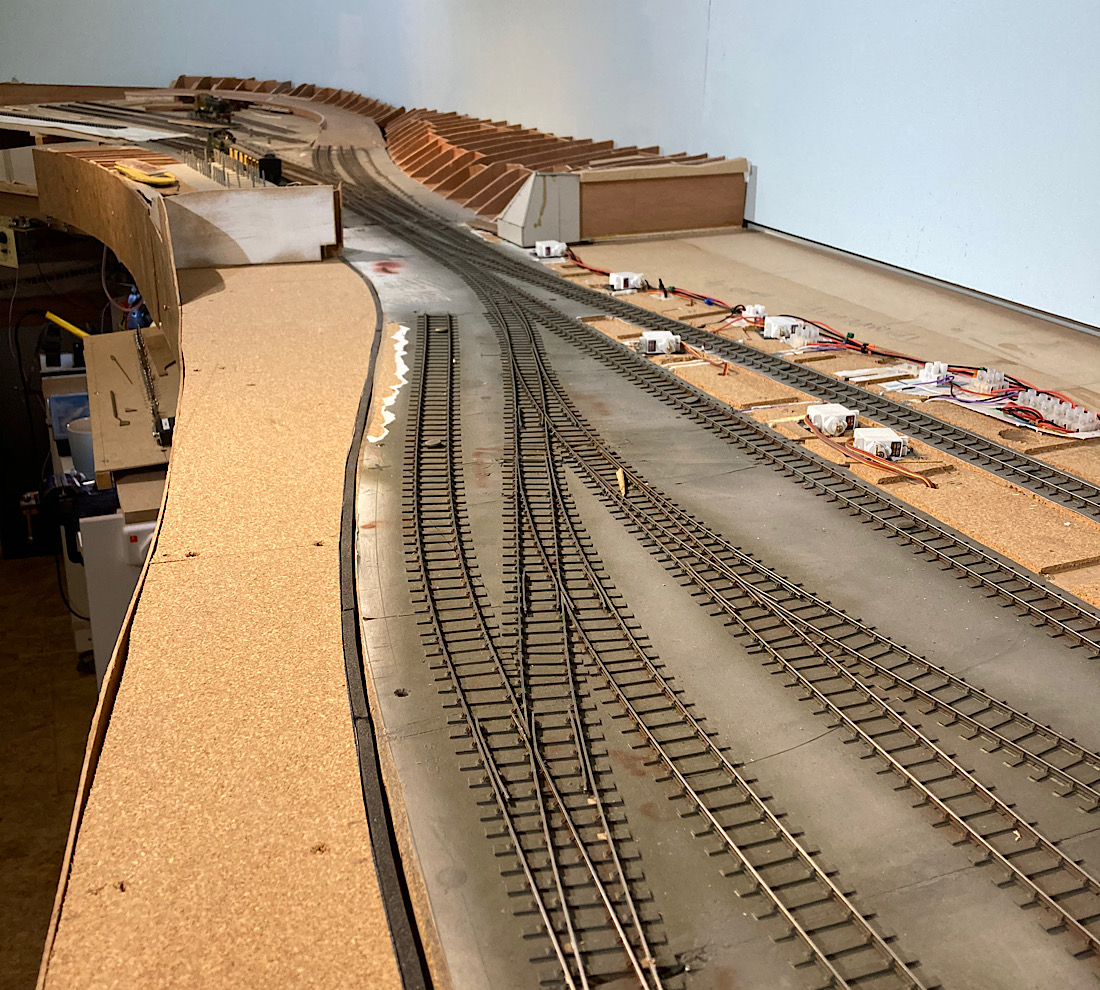 ...and now the cattle dock the other side of the bridge, as well as the land either side of the line, all gone in the twinkling of an eye 2787_141600_120000000.jpg 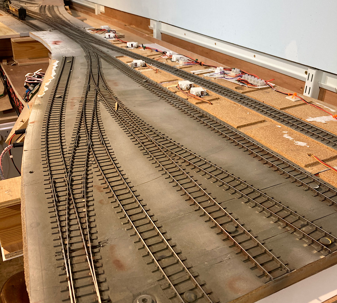 I've just noticed in this photo that the alignment of my lose heeled switches might challenge even EM wheels to go through smoothly? I'll add another photo or two from my ipad shortly ...cant seem to do from my Mac book(lovely machine, horrible operating system). Kind regards Andrew Edit: And here courtesy of my Ipad are the final two photos of the weekends progress Here the baseboard has gone altogether revealing the 1:100 climb under the station forecourt and the embankment on the far side of the road bridge. 2787_141639_080000000.jpg 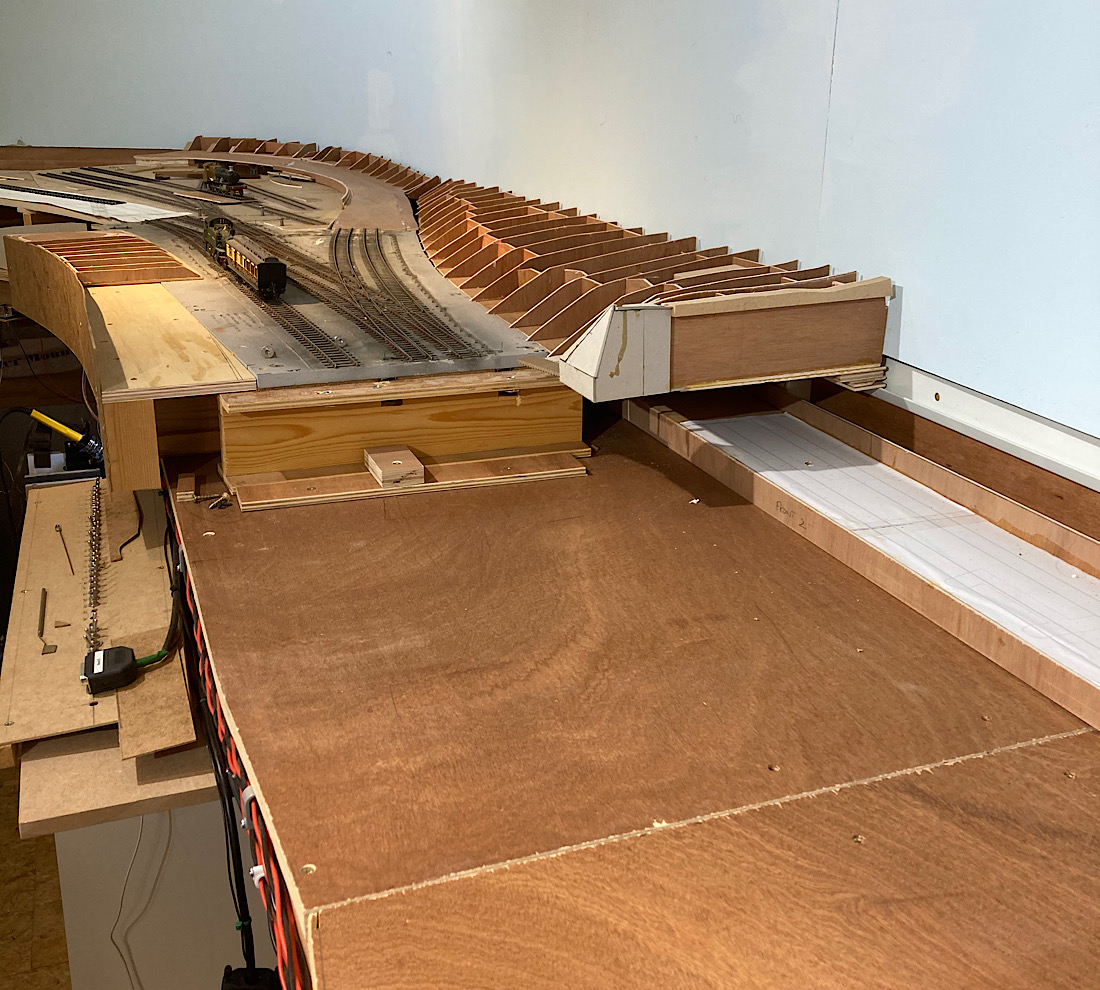 And here the track bed with the track just "posed" in position. 2787_141640_080000000.jpg 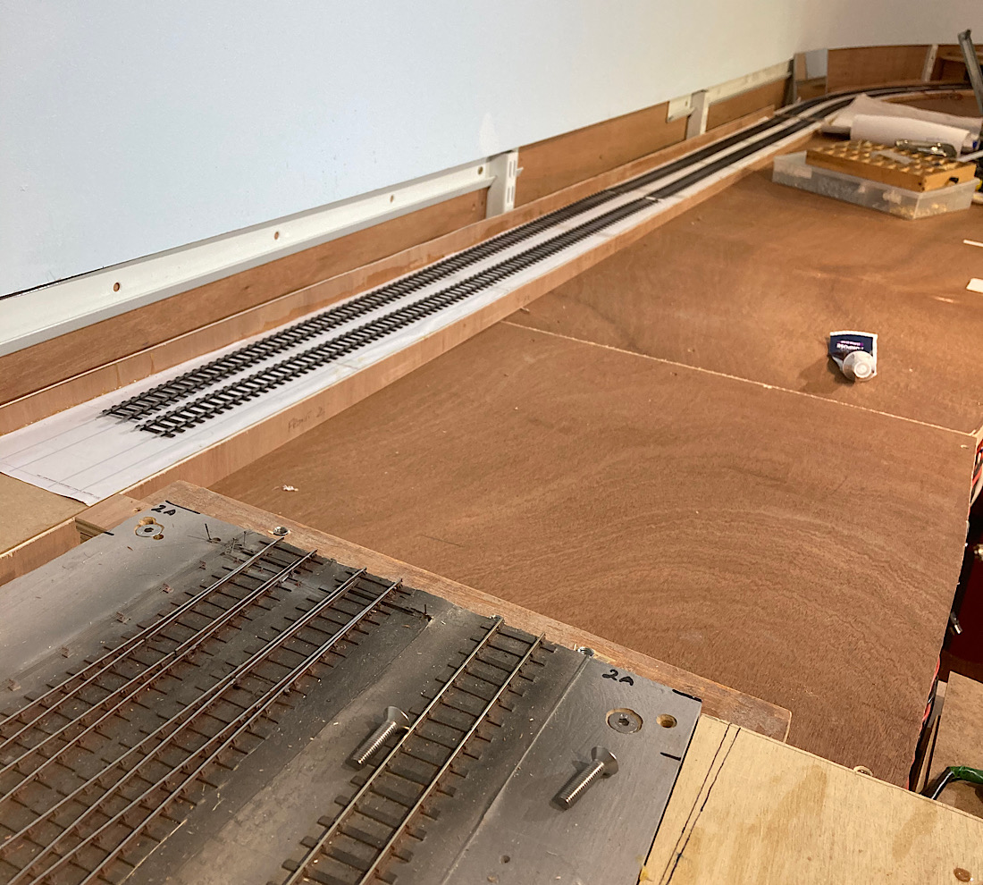 |
||
| Last edited on 14 Dec 2020 22:36 by Andrew Duncan |
|||
|
posted: 14 Dec 2020 21:22 from: John Lewis
click the date to link to this post click member name to view archived images |
Hi Andrew, Good to see your progress. I was aso interested in the loco and coach in photo 3. What period are you modelling? Best wishes John |
||
|
posted: 14 Dec 2020 22:28 from: Andrew Duncan
click the date to link to this post click member name to view archived images |
John Lewis wrote: Hi Andrew,Hello John Good to hear from you. I'm modelling slightly loosely around 1922. When I started with the original layout in 00 It was set in mid thirties but as I gained in abilities, firstly to build chassis that worked and secondly with Bob Moores lining pen, the ability to line coaches, my interest in earlier and in model terms, more unusual models flourished. So with encouragement from Iain I kept on getting earlier and earlier. In the days when he came to visit regularly he'd often quip "what year are you back to now". I'm not sure now that I shouldn't have gone back another ten years to enable me to legitimately have less Belpaire fireboxes around. The Dean goods and the 3232 class both come to mind when I think of beautiful engines rather spoilt by these late comers....however efficient they were! Anyway rather a long answer to the date question. The Prairie is early 1910ish(?) version which you will know, I've a terrible memory, is it the 31xx class, which I adapted from and Airfix ready to run model. Finecaste etched chassis, raised the cab height, rebuilt the bunker with that rather nice early straight backed one, and chopped off the later curved front end and replaced it with a plasticard one. I think I also replaced some of the boiler fittings as well. Rather like the coaches below, not a super acurate model, but it certinly has bags of character. The coach is just a Triang clerestory worked over with short Dean bogies( 6'6"?) some more convincing undergear and probably (I cant remember and I'm now up at the house) some gas pipes on the roof which i think make such a difference. I know that they aren't an actual prototype, but they do have the look and feel of a Dean coach and I find they mix very well with the Slaters lovely models, but take a fraction of the time to build/modify. Thanks for the questions John, it was nice to recall the modelling of them, and one day soon I hope to get back to more of that. Kind regards Andrew |
||
|
posted: 15 Dec 2020 08:21 from: Andrew Duncan
click the date to link to this post click member name to view archived images |
Hello John After i went to bed last night i realised that I could see very little of the loco and and the coach was none too clear either. If I get a chance this evening I'll post a couple of better pictures. Andrew |
||
|
posted: 15 Dec 2020 20:43 from: Andrew Duncan
click the date to link to this post click member name to view archived images |
Hello John Here are a couple of photos. The 31xx, as yet unnumbered and still with 00 axels. 2787_151526_150000000.jpg 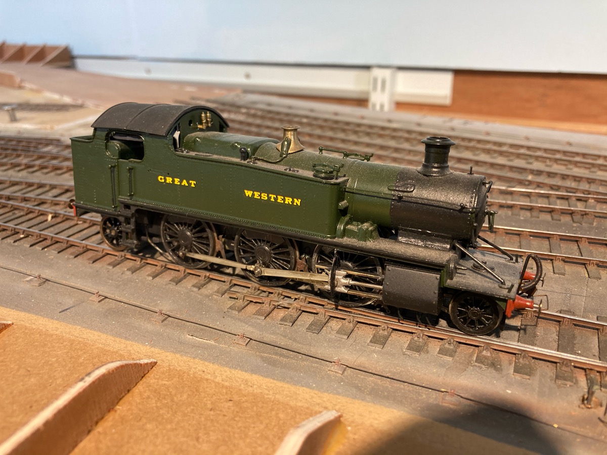 And here is a little more then just worked over, as I'd forgotten that I'd cut and shut two Triang "Dean" brakes into a semblance of a (?) which I know has been done on a number of occasions. And yes I did bother with some gas piping on the roof all set on tiny blocks of plasticard chopped up in my Northwest Shortlines guillotine. Extra hand rails on the ends etc etc. I really enjoy this sort of modelling. 2787_151527_210000000.jpg 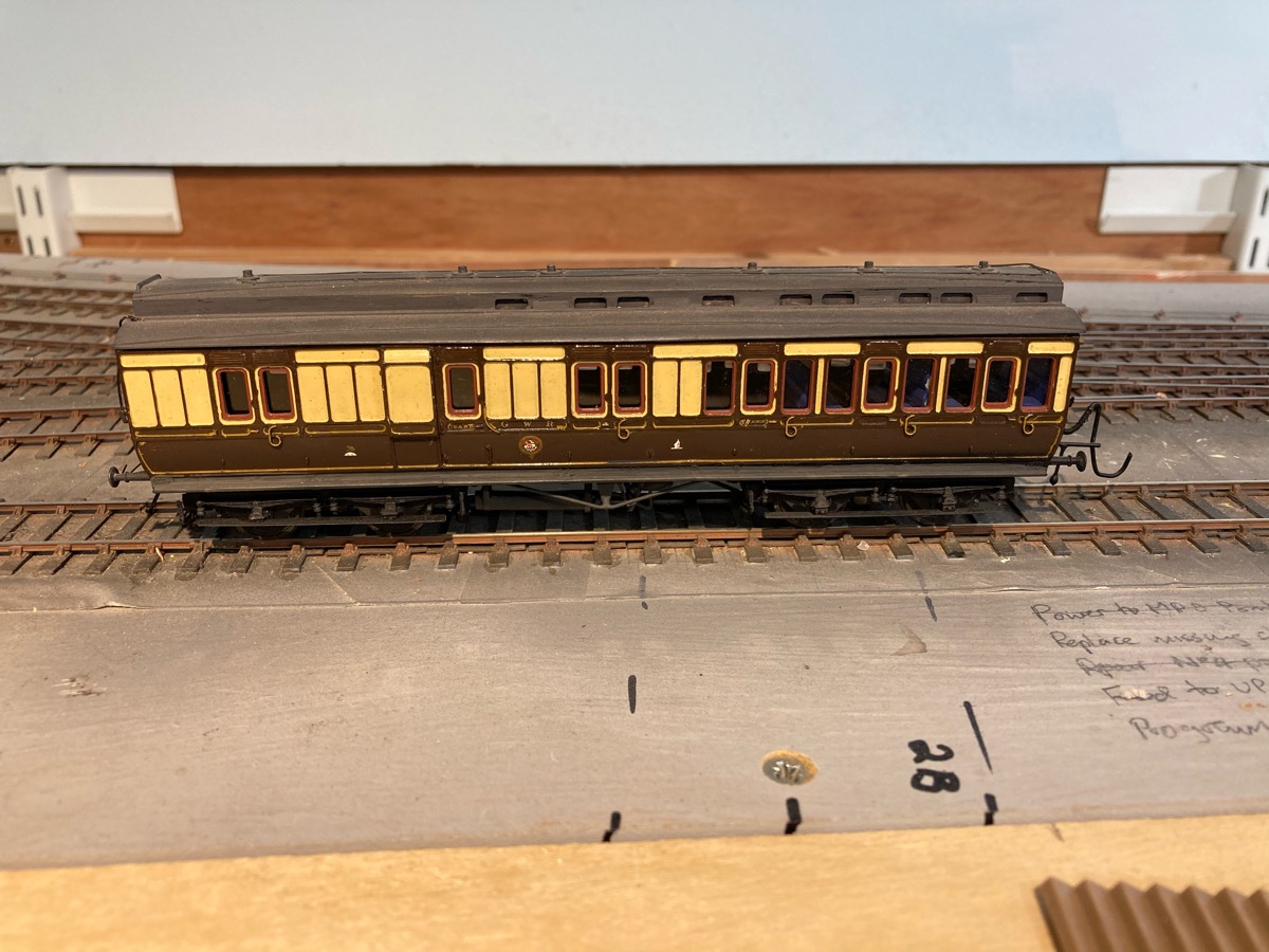 And just in case it reminds still too much of a 1960's Triang Clerestory.... here is a 1960's Traing Clerestory. Amazing what a decent pair of bogies and some more believable underpinnings do for the look. 2787_151528_060000000.jpg 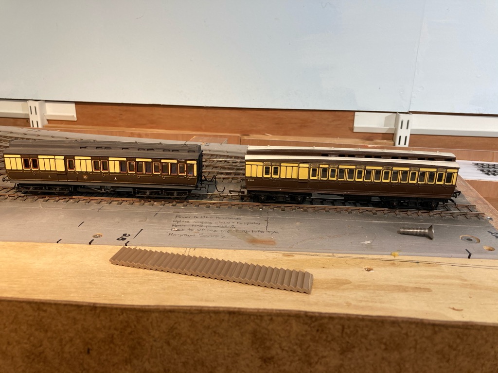 Kind regards Andrew |
||
|
posted: 15 Dec 2020 21:13 from: Rob Manchester
click the date to link to this post click member name to view archived images |
Hi Andrew, Slaters are planning to re-introduce some of the coach kits ( in 4mm/ft ) that they used to do such as the Dean clerestories. If you look at the Slaters site and download the pricelist there are quite a few items marked as 'not yet available' - not sure how they got the moulds back from Mr. Coopercraft. Hope you have plenty of Coopercraft wagon and van kits to go with all the locos you are planning to build David Geen had some lovely kits in his range, a nice man too and such a shame we lost him the same way as a few others in the hobby. Yes, bringing older models/kits up to a decent standard is good fun, I like it too - these days it is called up-cycling Rob |
||
| Last edited on 15 Dec 2020 21:14 by Rob Manchester |
|||
|
posted: 15 Dec 2020 22:49 from: Tony W
click the date to link to this post click member name to view archived images |
Hi Andrew. I sometimes wonder just how many of those Triang clerestories were butchered in an attempt to produce something reasonable, it must be hundreds if not thousands. My friend Mike Sargent who was hoping to build a model of Pen Mill in P4 produced a couple of decent looking coaches that way and they still do valiant service on Bodmin. Regards Tony. |
||
|
posted: 15 Dec 2020 22:58 from: John Lewis
click the date to link to this post click member name to view archived images |
Hi Andrew, Thank you for sharing these photos. The 2-6-2T is coming on nicely, the most obvious thing I think, is that the motion dos not really look like steel. Perhaps giving it an oily looking wash might help? The clerestory coach on the left looks splendid, the Horby one on the right of the pair looks wrong. It needs the droplights painted mahogany and the bolection mouldings were teak. The roof certainly needs painting in gray really, unless your model is in 'just out of the paint shop' condition. Best wishes John |
||
|
posted: 15 Dec 2020 23:00 from: Nigel Brown click the date to link to this post click member name to view archived images |
Peter Denny had quite a few suitably repainted on his Buckingham layouts. Nigel |
||
|
posted: 15 Dec 2020 23:13 from: Andrew Duncan
click the date to link to this post click member name to view archived images |
Rob Manchester wrote: Hi Andrew,Hello Rob I honestly don’t think I’ll live long enough to build the kits I do have, so although I’m glad Slaters are bringing them back, because bogies aside, they are really excellent models, I doubt I shall find myself in the market for more. One day I’ll take a photo of my horrifying pile of unbuilt kits and you’ll understand. You might even take pity on me and offer to build a few for me...? But yes I’m not short on wagons. Just need to find a part time job so that I have time build all this stuff.. Building rolling stock is really my main passion, but I’ve hardly done any since this thread started six years ago. The Somerset link defeated me? Is Coopercraft no longer, and are/ were they based there? Kind regards Andrew |
||
|
posted: 15 Dec 2020 23:20 from: Andrew Duncan
click the date to link to this post click member name to view archived images |
Tony W wrote: Hi Andrew.Hello Tony Good to hear I’m in such exhaulted company with the clerestories. If Mike was planning on building Pen Mill in P4, he must have had a very large space. Do you recall just how big it was going to be? Kind regards Andrew |
||
|
posted: 15 Dec 2020 23:30 from: Andrew Duncan
click the date to link to this post click member name to view archived images |
John Lewis wrote: Hi Andrew,Hello John Thanks for your kind comments on the Prairie, I do agree the motion isn’t right. Painting a wash would improve things but I also recall that the crosshead is a white metal casting and is a bit of a let down when compared to the rest of the chassis kit. As for the unaltered coach I only put it there as a comparison to show off! When I get to doing a job on it I shal do what you suggest and replace the bogies and undercart as well. Thanks again Andrew |
||
|
posted: 15 Dec 2020 23:40 from: Andrew Duncan
click the date to link to this post click member name to view archived images |
Nigel Brown wrote: Peter Denny had quite a few suitably repainted on his Buckingham layouts.Hello Nigel Funny you should mention Peter Denny, because I bought three clerestories on eBay a few years ago which been repainted in fake teak and actually look quite good. So that is two notable layouts that have used them. I’m in good company....I can sleep soundly tonight! Kind regards Andrew |
||
|
posted: 16 Dec 2020 00:12 from: Rob Manchester
click the date to link to this post click member name to view archived images |
Hi Andrew, Slaters originally designed and produced a fair bit of 4mm scale rolling stock but, as I understand it, they really wanted to stay true the 7mm range. Some of the 4mm range was stopped for a while and then C&L ( quite a few owners ago ! ) purchased the moulds for the Midland and private owner wagons and they thus appeared on the market branded as a C&L product. A while later Coopercraft ( originally of London but later in Somerset ) relaunched some coach kits previously mastered by Slaters - including the Dean clerestories. Soon there were issues with the supply of anything from Coopercraft ( which by this time also included products previously sold under brand names such as Ian Kirk and Mailcoach ). RMweb has lots of posts describing unfulfiled orders and lack of refunds. The website is still up and running even to this day but DO NOT order anything unless you wish to say goodbye to some money. The original and essential Coopercraft GWR rolling stock range was mastered by the original owners in London and is really the only way to get plastic injection moulded stuff that looks good and suits the early ( 1900-> ) GWR periods. I assume the moulds are in Somerset but would be better off with somebody would could get the kits back on the market. I would be happy to have some of your kits but you won't get them back There is a Mallard 57' railmotor kit on Ebay today - bidding starts at £99.00, now where did I put my three unbuilt ones ? Rob |
||
|
posted: 16 Dec 2020 11:59 from: Tony W
click the date to link to this post click member name to view archived images |
Andrew Duncan wrote: Tony W wrote:Hi Andrew.Hello Tony Hi Andrew. Referring back to an earlier post, short Dean bogies were 6'4" wheelbase (I had to look it up but 6'6" didn't sound quite right) and they always looked rather odd to me under a passenger vehicle. When it comes to things Great Western, I have to confess that I am speaking largely from a position of ignorance, my true allegiances lying somewhat further east. Because I have been involved with the North London Group's Bodmin layout for so long people tend to make the not unnatural assumption that I must be a fan of the GWR (although something must have rubbed off). In truth I made a far larger physical contribution to the group's previous layout Heckmondwike (LMSR) than I ever did Bodmin. There were enough true GWR devotees in the group for that. My total contribution to the rolling stock was a Ratio brake van and an ex Heckmondwike Ratio LMS box van. That is not to say that I like the layout any the less, I wouldn't have spent so many hours helping to keep it going if I hadn't. Regarding the Triang clerestories, I remember seeing numerous articles in the model railway press during the 1960's detailing various conversions people had done with them. Regarding Mike's plans for Pen Mill, I'm afraid that is as far as his project ever got. It was basically his pipe dream, much as Brimsdown was mine for many years. Mike had a modern house in Potters Bar with a built in garage barely big enough for a car let alone a decent layout. The car spent most of its time on the drive. After Bodmin Mike started a smaller P4 layout he called Pen Till using the stock intended for Pen Mill. The layout developed sufficiently that it was exhibited several times. I think he hoped to move to a house with a railway room when he retired, but unfortunately developed Hodgkins lymphoma, a form of cancer and his dream died with him. This is partly why I have more than a passing interest in your project. For many years the NLG used to award a Pen Till trophy in his memory to those the committee considered had made a major contribution to the NLG and P4. Regards Tony. |
||
| Last edited on 16 Dec 2020 12:07 by Tony W |
|||
|
posted: 16 Dec 2020 22:11 from: Andrew Duncan
click the date to link to this post click member name to view archived images |
Tony W wrote:Hello Tony You maybe speaking from a position of ignorance but as you can see I'm a bit out of touch myself when I refer to a Dean 6'4" incorrectly ...like you I thought it sounded wrong, but went the other way and wondered if it was it 6' 8"? I'm sure if I asked John (Lewis) he'd put us right. Funnily enough I rather like this short bogie whether on passenger vehicles or otherwise, very pretty. Thank you for the story behind a part of your reason for your interest in my version. Its a good one even if it does have a premature and sad ending. What happened to Pen Till, and what a good name for someone waiting to build his magnum opus of Pen Mill? A nice quiet sense of humour. Kind regards Andrew |
||
|
posted: 17 Dec 2020 12:35 from: Tony W
click the date to link to this post click member name to view archived images |
Andrew Duncan wrote: Tony W wrote:Hello Tony Hi Andrew. The Dean bogies certainly do have character, I'll give you that. Many years ago I had a good look at a set under a coach at Didcot. Their suspension system is quite intriguing. Pen Till was taken on by some fellow members of the North London Group after Mike died with the intention of keeping it going and indeed it was exhibited in Mike's memory a couple of times, but problems began to make themselves know. Partly being due to Mike's choice of Steel rail and keeping the layout in a garage. But the biggest problem was caused by Mike using Bakers fluid to make the check and wing rails go rusty. The scenic effect was great to begin with, but Bakers fluid is very corrosive and the rust did not stop spreading with serious detrimental effects. In the end it came down to a choice of rebuilding a large portion of the track work or scrapping it and sadly the latter course was eventually chosen. In retrospect Mike's main claim to fame was that he wired up both Heckmondwike and Bodmin pretty much single handed and the fact that Bodmin is still going nearly 40 years later is testament to the standard of his workmanship. Regards Tony. |
||
|
posted: 17 Dec 2020 16:05 from: John Lewis
click the date to link to this post click member name to view archived images |
There were Dean 6ft 6in bogiees a swell as 6ft 4in, but you cannot tell them apart without a ruler (or a micrometer in N gauge) I think the 6ft 6in bogies were put under a few passenger brake vans. What I thought odd was that there were 6ft 4in broad gauge bogies- I wondeer how they rode! John |
||
|
posted: 17 Dec 2020 23:51 from: Andrew Duncan
click the date to link to this post click member name to view archived images |
John Lewis wrote: There were Dean 6ft 6in bogiees a swell as 6ft 4in, but you cannot tell them apart without a ruler (or a micrometer in N gauge) I think the 6ft 6in bogies were put under a few passenger brake vans.Hello John If only I’d stayed quiet I’d have got away it! So there were 6’6”” bogies, I live and learn but mine are the 6’4”” 247 Developement cast ones, which I rather like. They ride well, simple and quick to put together and more than adequate detail for a “layout” coach. Compared to Danny Pinnocks lovely but complicated bras etched ones, I’d go the 247 route every time. Which I suppose nails my colours to the 80/20 mast once again. The 6’4” long bogie 7’0”” wide sounds an unlikely beast.. sort of leaves me feeling why bother with a bogie at all, wouldn’t a single wheel set have the job? Anyway thanks for your expertise John Kind regards Andrew |
||
|
posted: 18 Dec 2020 00:34 from: Andrew Barrowman
click the date to link to this post click member name to view archived images |
"wouldn’t a single wheel set have the job?" We tried that. http://en.wikipedia.org/wiki/Bennie_Railplane |
||
|
posted: 18 Dec 2020 03:51 from: Matt M.
click the date to link to this post click member name to view archived images |
Just for completeness and apropos of nothing the New South Wales Government Railway built four types of Dean bogies between 1910 and 1914. All with a nine foot wheelbase. Cheers, Matt M. |
||
|
posted: 18 Dec 2020 06:29 from: Andrew Duncan
click the date to link to this post click member name to view archived images |
Andrew Barrowman wrote: "wouldn’t a single wheel set have the job?"Hello Andy This story is a bit of sad one, but I must say it was also an eyesore. Just imagine one of those slung above our railway lines, worse even than the catenary system, which is pretty ugly. But who would have guessed.... Just for clarity, I meant a conventional wheel set straddling two rails, that might have served almost as well. But seriously, probably not! Kind regards Andrew |
||
|
posted: 18 Dec 2020 07:58 from: Hayfield
click the date to link to this post click member name to view archived images |
Tony W wrote: Andrew Duncan wrote:Has anyone ever produced etched sides for the Triang coaches ? either as they are or cutting and shutting them to a correct length, or even doing the same for the newer versions.Tony W wrote:Hi Andrew.Hello Tony Or did the Slaters coaches negate the need to |
||
|
posted: 18 Dec 2020 07:59 from: Hayfield
click the date to link to this post click member name to view archived images |
Tony W wrote: Andrew Duncan wrote:Tony W wrote:Hi Andrew.Hello Tony |
||
|
posted: 18 Dec 2020 09:34 from: Nigel Brown click the date to link to this post click member name to view archived images |
Strictly speaking the Dean "bogies" were trucks; I don't think they had a central pivot. Nothing wrong in principle with a 6' 4" truck; remember Collett produced 7' bogies for much longer vehicles, after experiments with ride. With longer vehicles Dean moved to an 8' 6" truck, then 10' for the longest. I believe the trucks had a reputation for a comfortable ride. Here's a pic of a D15 brake third in 3mm/ft with the 6' 4" truck: 528_180433_210000000.jpg 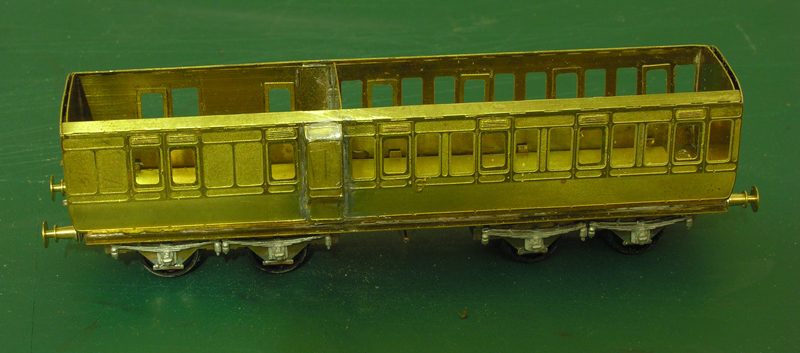 Nigel |
||
|
posted: 18 Dec 2020 11:15 from: a_nummelin
click the date to link to this post click member name to view archived images |
Nigel Brown wrote: Strictly speaking the Dean "bogies" were trucks; I don't think they had a central pivot. ...This seems to be a common misconception, as is the commonly used description of them being "centreless". The critical point is that there is no weight carried by the central pivot that fixes the centre of rotation of the bogie. I have heard that the only true centreless bogie may have been that fitted to Dean's experimental 4-4-0T no. 1 but I haven't seen a GA drawing to confirm this. The scan below is from P. Kay's reprint of Sidney Stone's "Railway Carriages & Wagons, their design & construction" of 1903 and shows the central pivot - more clearly in the lower figure. I've recently had "fun" building a wagon with bogies suspended on this principle - but with lockdown I've yet to be able to test it: I need to do some new layout planning (with Templot) and start baseboard construction... |
||
| Attachment: attach_3188_2547_scan.jpg 13 | |||
|
posted: 18 Dec 2020 11:39 from: Matt M.
click the date to link to this post click member name to view archived images |
Hi Nigel, I may be wrong as this isn't a strong point but if my memory serves Dean bogies have a central pivot. They don't bear on it unlike the more usual bogie designs. Dean bogies are about the secondary suspension. The full name that I know is Dean Hung Suspension Bogies. You have two fixed bolsters that are attached to the underframe of the carriage at each end by a hefty post. These bolsters ride on volute springs. Two on each side became standard to help with higher speeds as the early ones had stability problems over 55 mph. So eight in all. These springs not only carry the weight of the vehicle but also dealt with the turning and lateral displacement of the bogie truck. They are connected to the bogie frame by hanger bolts that transmit the loads to brackets mounted on the bogie solebars. The hanger bolts have spherical bearings at each end. Effectively the carriage body becomes the bolster. He had two distinct suspension designs. Inner and outer. The outer ones are referred to as centreless but that refers to the lack of bolster, not guide pin. (As just pointed out by a_nummelin jn his post). The outer units had restrictions with longer bogies as they interfered with the amount of pivot so fell out of favour with the development of longer coaches and matching longer bogies. Hope this is of use. Matt M. |
||
|
posted: 21 Dec 2020 09:01 from: Andrew Duncan
click the date to link to this post click member name to view archived images |
Rob Manchester wrote: Hi Andrew,Hello Rob Thank you for the story behind the the Slaters and Coopercraft history. I did look , albeit briefly on Slaters a few days ago and didn't see the Deans, or the Toplights for that matter, but thats probably not a bad thing in view of my previous comments. Did a bit more wring up of the hidden tracks yesterday between packing parcels of Riedel Glasses! Kind regards Andrew |
||
|
posted: 21 Dec 2020 09:11 from: Andrew Duncan
click the date to link to this post click member name to view archived images |
Hayfield wrote: Has anyone ever produced etched sides for the Triang coaches ? either as they are or cutting and shutting them to a correct length, or even doing the same for the newer versions. Hello John Yes for the newer version that have no relief panelling there is company that still produce them I believe, in fact in my kit pile I have a few. I built one of them a few years ago and found them very good . One needs to be a bit brutal with the original coach and I cant now remember how far i went i detailing it, but I do recall being pretty satisfied with end result. If I get spare moment I'll have a dig around in my pile and if I can see the name. Kind regards Andrew sorry about the formatting, didnt have time to change it. |
||
| Last edited on 21 Dec 2020 21:03 by Andrew Duncan |
|||
|
posted: 21 Dec 2020 09:29 from: Nigel Brown click the date to link to this post click member name to view archived images |
I think the Coopercraft problems relate to the current owner who never really got things moving after he took things on. I too lost some money by ordering stuff which he seemed incapable of fulfilling but also seemed incapable of issuing refunds. A pity, there's some good stuff there. He also has the Blacksmith/Mallard kits. |
||
|
posted: 21 Dec 2020 13:14 from: Phil O
click the date to link to this post click member name to view archived images |
About the only thing that you can get from him are the Blacksmith etches, but I would advise that you only make your purchase at a show that he's at, the only one that I know that he attends is RailWells in August, once exhibitions restart. Cheers Phil. |
||
|
posted: 21 Dec 2020 19:20 from: Rob Manchester
click the date to link to this post click member name to view archived images |
Andrew Duncan wrote: Hello RobHello Andrew, This is from the current Slaters list. 2001_211416_590000000.png  It seems a fair bet that NYA means 'not yet available'. Rob P.S. for Phil - I have never been to Railwells and have purchased from Paul Dunn's stand. I will post the location if I remember ! |
||
|
posted: 21 Dec 2020 21:17 from: Andrew Duncan
click the date to link to this post click member name to view archived images |
Nigel Brown wrote: Strictly speaking the Dean "bogies" were trucks; I don't think they had a central pivot. Nothing wrong in principle with a 6' 4" truck; remember Collett produced 7' bogies for much longer vehicles, after experiments with ride. With longer vehicles Dean moved to an 8' 6" truck, then 10' for the longest. I believe the trucks had a reputation for a comfortable ride.Hello Nigel Thats a beautiful little model, is it yours, and if so have you a later finished version of it? I have one , unbuilt from Blacksmiths, in my stash. A very attractive cosy little coach! Andrew |
||
|
posted: 21 Dec 2020 22:00 from: Rob Manchester
click the date to link to this post click member name to view archived images |
Hi Nigel, Nice little coach - agree with Andrew. Does the lack of a central pivot mean the "bogies" are actually radial trucks as used by the LNWR and Metropolitan for example. I assume they have a side control mechanism that allows them to move laterally into a curve. Must check my sources - I feel I should know this Rob |
||
|
posted: 21 Dec 2020 22:53 from: Matt M.
click the date to link to this post click member name to view archived images |
HI Rob, Your questions about the bogies was answered by myself and a_nummelin who also posted drawings to help explain. The Dean bogie has a pivot. It just doesn't bear any weight in the vertical plane. Regards, Matt M. |
||
|
posted: 22 Dec 2020 16:18 from: Nigel Brown click the date to link to this post click member name to view archived images |
Andrew Duncan wrote: Nigel Brown wrote:Strictly speaking the Dean "bogies" were trucks; I don't think they had a central pivot. Nothing wrong in principle with a 6' 4" truck; remember Collett produced 7' bogies for much longer vehicles, after experiments with ride. With longer vehicles Dean moved to an 8' 6" truck, then 10' for the longest. I believe the trucks had a reputation for a comfortable ride.Hello Nigel Here's a pic of it painted: 528_221117_180000000.jpg 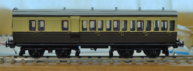 Not exactly finished; it needs the insignia for a start. Nigel |
||
|
posted: 22 Dec 2020 23:59 from: Andrew Duncan
click the date to link to this post click member name to view archived images |
Matt M. wrote: HI Rob,Hello Matt and Andrew (Nummelin) Thank you both for your full explanations of the Dean Bogie system, you obviously know a thing or two about the subject. Real education! Kind regards Andrew |
||
|
posted: 23 Dec 2020 00:11 from: Andrew Duncan
click the date to link to this post click member name to view archived images |
Nigel Brown wrote:Hello NigelHello Nigel Thanks for posting the photo of the almost complete coach. Bags of character and nicely done. What sort of couplings are you using incidentally? Kind regards Andrew |
||
|
posted: 23 Dec 2020 01:39 from: Matt M.
click the date to link to this post click member name to view archived images |
Hi Andrew, After ten years of sorting New South Wales Mechanical Branch drawings I started to be asked all the horrible technical questions by modellers. The bogies are of interest as the NSWGR produced about 52 varieties of four wheeled and 6 wheeled bogies between 1874 and 1964. And I get asked about them by model manufactures as to what goes under what in a given period, (they change and move around). And when you look for the changes that are cosmetically obvious you also start to appreciate the engineering behind the design. I had to do the Dean stuff from memory as I was time short and couldn't find either my copy of Sidney Stone's opus or a presentation paper on bogie design from the late 1950's I think by W. S. Graff-Baker which is fascinating reading in its own right. The problems they have to overcome to get rolling stock to track straight and true are phenomenal. Glad it was of help and interest. Enjoying your build. Matt M. |
||
|
posted: 24 Dec 2020 20:35 from: Andrew Duncan
click the date to link to this post click member name to view archived images |
Matt M. wrote: Hi Andrew,Thanks Matt, it was indeed.! As it's Christmas Eve, I'd like to thank everyone who reads this thread, and indeed those of you who join in, for making the contribution to this layout's success. By this I mean roughly two things. Firstly its very encouraging seeing that others are interested in what I am doing and this helps spur me on especially at the low moments. And secondly, in a practical sense I've often been guided on best practice principles and or reminded about pretty basic stuff, to avoid future mishaps. A good example of this, a page or so back, was Tony reminding me not to lay a very long length of continuous unbroken rail to avoid expansion problems. This was good advice and although it wasn't new news to me (I've been dabbling in model railways since i was a boy) I was so concentrated on finding a way to make a continuous reliable 3'6" curve, thoughts of gapping to allow for expansion went right out of my head. So thanks everyone for reading about my progress and the feedback. You make it very enjoyable for me. Happy Christmas to you and I hope for an easier 2021! Kind regards Andrew |
||
|
posted: 25 Dec 2020 20:24 from: Andrew Duncan
click the date to link to this post click member name to view archived images |
A bit more progress this afternoon whilst the family were playing cards... The first photo shows the line running under the station forecourt largely complete. 2787_251503_090000001.jpg 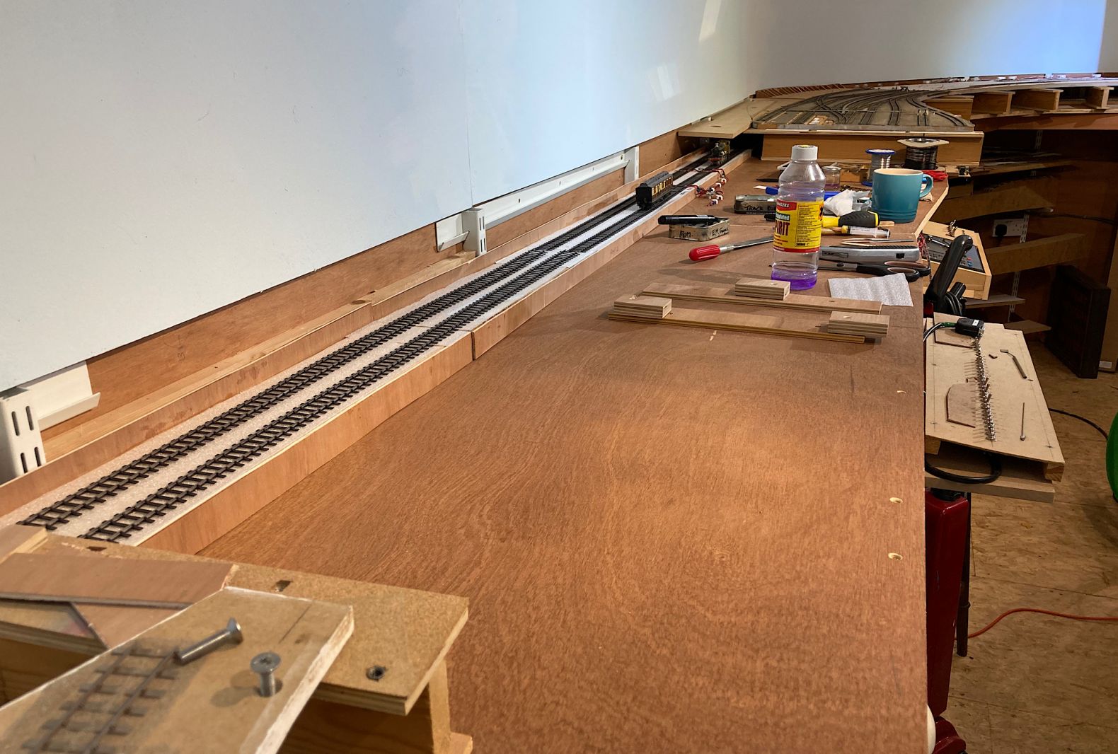 The second one shows the main station forecourt board installed again. 2787_251503_110000003.jpg 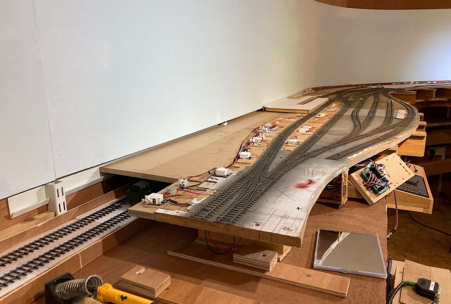 The third some of the scenery and platforms back in place 2787_251503_100000002.jpg 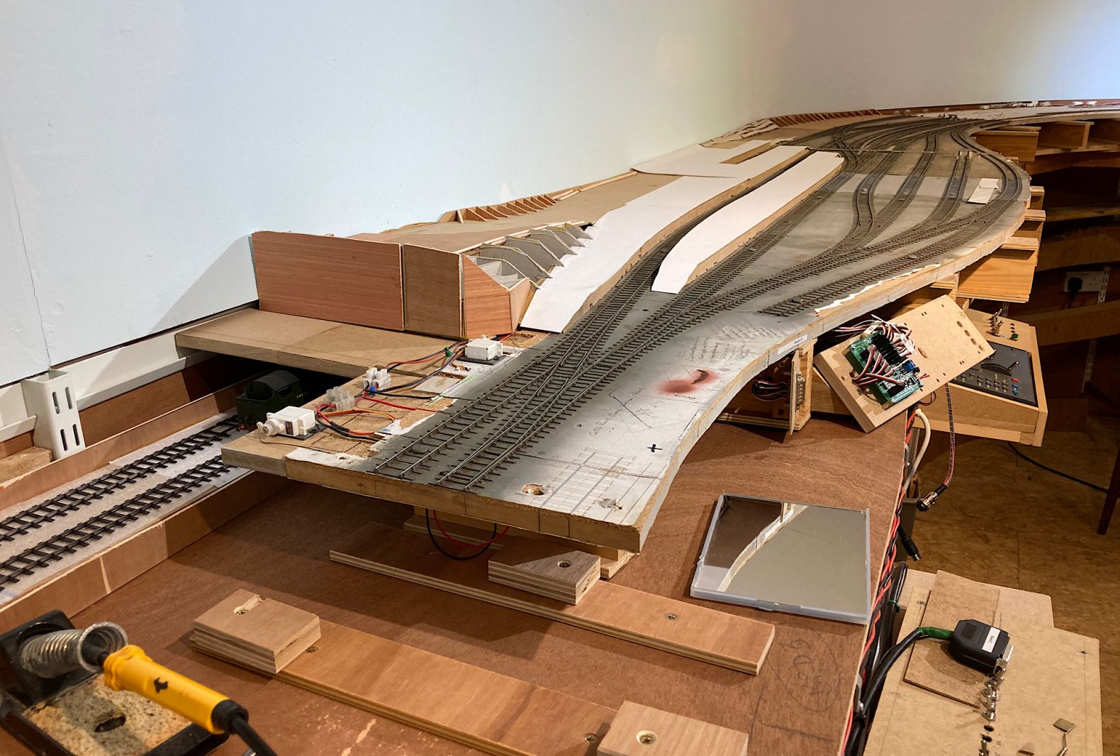 And the forth the bridge is back and it occurred to me that you can see the layers of construction pretty clearly. The 43xx Mogul, just clears the underside of the board that holds up the bridge. Was this good judgement or luck...? 2787_251503_090000000.jpg 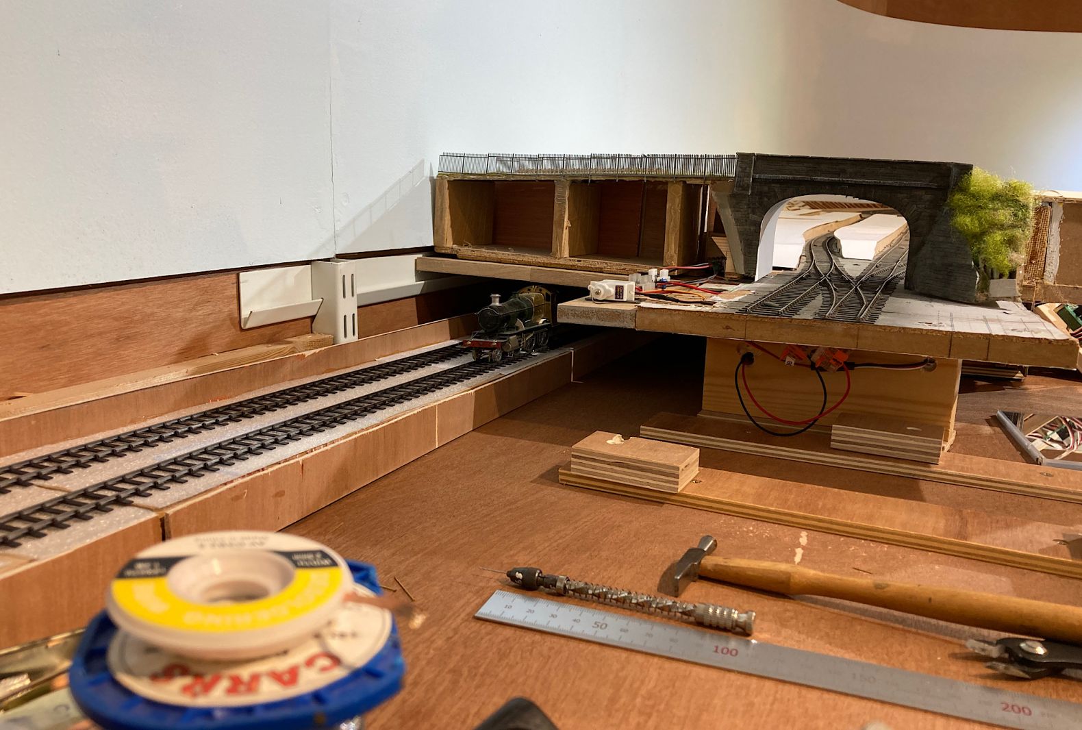 Happy Christmas Andrew |
||
|
posted: 25 Dec 2020 21:30 from: John Lewis
click the date to link to this post click member name to view archived images |
Hi Andrew, If you put a small model roof onto the upper ends of the spur uprights, you could produce some slightly odd-looking white buildings. 😒 John |
||
|
posted: 27 Dec 2020 08:18 from: Andrew Duncan
click the date to link to this post click member name to view archived images |
Unusual idea John.....I’ll need to think that one through! Hello John ( Hayfield) The coach sides you were asking about and that I was referring to are actually 247 Developements which I’d completely forgotten and was rarher surprised to see....! Below a couple from my unbuilt pile! 2787_270318_080000000.jpg  Kind regards Andrew |
||
|
posted: 27 Dec 2020 09:06 from: Hayfield
click the date to link to this post click member name to view archived images |
Andrew Thanks for the update, I had a quick look at the 247 website, which seems to be in development (coach section unattached/no internal link) and sadly they seem no longer available |
||
|
posted: 27 Dec 2020 12:10 from: Nigel Brown click the date to link to this post click member name to view archived images |
Andrew Duncan wrote: Nigel Brown wrote:Hello Nigel On the pic the pockets for the scroll irons look a bit heavy; in the flesh I don't notice them. The couplings are B&B, which I like a lot. They can be a bit fiddly to assemble but I find one soon gets the hang of them. If one isn't going to turn stock it's possible to simplify the process by having a loop at just one end and the remote uncoupling latch at the other. If one isn't interested in the remote uncoupling feature (which allows you to uncouple at one spot then push the vehicle to where you want it) then you can omit the latch entirely. The couplings come ready-blackened, which is useful. Nigel |
||
|
posted: 28 Dec 2020 00:16 from: Andrew Duncan
click the date to link to this post click member name to view archived images |
Nigel Brown wrote:
Hello Nigel Thanks for your answers and thoughts on the B&B couplings. I’m going to show my ignorance here and ask you to either remind me or tell me what the scroll irons are. I’ve a dim memory that I shouldn’t need to be asking this question but can’t for the life of me remember ( or perhaps ever knew) what they were? Many thanks Andrew Here are a few pictures of progress today .... The curved track that runs below the MPD and branch line out of place during track laying. 2787_271902_180000000.jpg  The junction board just put back in place which, along with its neighbouring MPD board when I replace that as well, will allow me to The check clearances with the hidden tracks 2787_271903_530000000.jpg  2787_271905_380000000.jpg 2787_271905_380000000.jpg |
||
|
posted: 28 Dec 2020 01:00 from: Martin Wynne
click the date to link to this post click member name to view archived images |
Hi Andrew, I have copied your photos to the new Templot Club site: http://85a.uk/templot/club/index.php?media/categories/posted-attachments.2/ because it is now too late to include them in the archived gallery here. It's likely that your post here will be the very last one on this old Templot Club site, unless someone gets in very quick. Martin. |
||
|
posted: 28 Dec 2020 01:07 from: Rob Manchester
click the date to link to this post click member name to view archived images |
Well done Andrew, maybe the last post is yours..... Rob |
||
|
posted: 28 Dec 2020 07:32 from: Andrew Duncan
click the date to link to this post click member name to view archived images |
Martin Wynne wrote: Hi Andrew,Hello MartinHave i missed something....? Andrew |
||
|
posted: 28 Dec 2020 07:39 from: Martin Wynne
click the date to link to this post click member name to view archived images |
Andrew Duncan wrote: Hello MartinHi Andrew, Maybe? See: topic 3837 topic 3844 cheers, Martin. |
||
| Please read this important note about copyright: Unless stated otherwise, all the files submitted to this web site are copyright and the property of the respective contributor. You are welcome to use them for your own personal non-commercial purposes, and in your messages on this web site. If you want to publish any of this material elsewhere or use it commercially, you must first obtain the owner's permission to do so. |