Templot Club Archive 2007-2020
|
|||
| author | remove search highlighting | ||
|---|---|---|---|
|
posted: 19 Nov 2014 08:08 from: Hayfield
click the date to link to this post click member name to view archived images |
Never seems to be much put up on this part of Templot, thought I would just put up a few photos of a 1-8 single slip I am building, the plan was produced with the use of Martins new video 982_190310_310000000.jpg 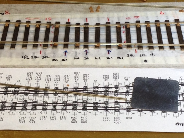 Both stock rails fitted and as you can see I use 5 pieces of very thin copperclad to solder the obtuse crossings to. These will be cut back to the rail sides towards the end of the build process and stuck in place 982_190311_460000000.jpg 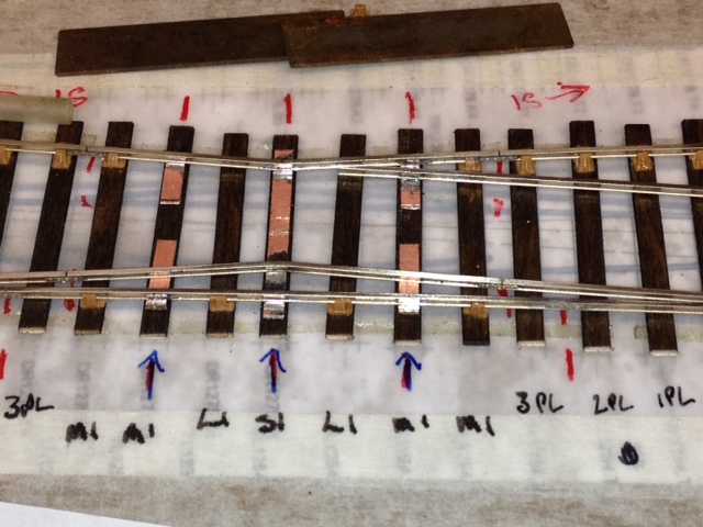 I make the slide rails in one piece and notch the rail joins, then add etched fishplates. This is because I want maximum flexibility of the blades for ease of movement. I only put one solder joint in the centre for the same reason On double slips the tiebar movement is very stiff on this method. I have made these rails in 3 pieces soldering cast metal fishplates to the centre rail only, this makes for a very free movement. 982_190320_270000000.jpg 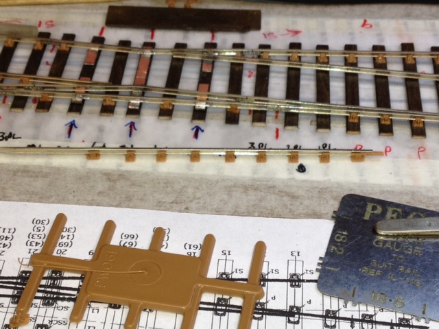 Two of the crossing rails have normal and bridge chairs, these are threaded on before soldering the rail in place 982_190324_300000000.jpg 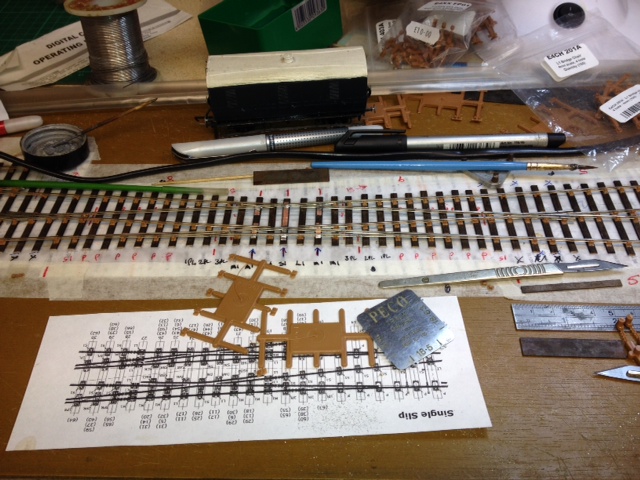 All 4 crossing rails in place. Just the check rails and other slip rail to make and fit |
||
| Attachment: attach_1996_2577_points81.jpeg 686 | |||
| Last edited on 19 Nov 2014 11:31 by Hayfield |
|||
|
posted: 19 Nov 2014 08:42 from: Hayfield
click the date to link to this post click member name to view archived images |
undefined |
||
| Last edited on 19 Nov 2014 08:45 by Hayfield |
|||
|
posted: 19 Nov 2014 11:18 from: Martin Wynne
click the date to link to this post click member name to view archived images |
Hayfield wrote: undefinedHi John, There are 6 photos from you today, all uploaded fine in the Gallery, see: http://85a.co.uk/forum/gallery_view.php?user=982#gallery_top Are you using Google Chrome? They keep trying to make it faster by ditching half the functionality, so the gallery images may not insert into your post in Chrome. Try using Firefox or Internet Explorer, or you can right-click on the images to get the URL and insert it using img tags. Or I can put them in your post for you if you wish. regards, Martin. |
||
|
posted: 19 Nov 2014 11:36 from: Hayfield
click the date to link to this post click member name to view archived images |
Martin Wynne wrote: Hayfield wrote:undefinedHi John, Martin Thanks, I am using Google chrome (as I am used to it) as you can see it works fine with Internet Explorer. 982_190343_530000000.jpg 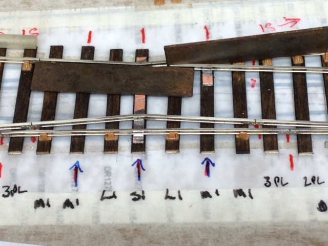 Here is a photo of how I gauge the first crossing rail, after doing this check its in gauge with the other stock rail |
||
|
posted: 23 Nov 2014 08:29 from: Hayfield
click the date to link to this post click member name to view archived images |
982_230326_250000000.jpg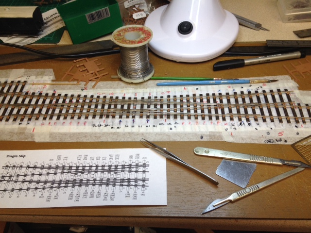 Rails now fitted and tested with a long wheelbase van, will test next with a loco before fitting the Exactoscale slip and obtuse crossing chairs and anchoring down the central crossing to the sleepers |
||
| Last edited on 23 Nov 2014 08:30 by Hayfield |
|||
|
posted: 26 Nov 2014 07:48 from: Hayfield
click the date to link to this post click member name to view archived images |
I thought a couple of images of how I build the obtuse crossings may assist 982_260217_530000000.jpg 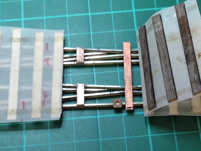 As you can see I build my turnouts and crossings on tracing paper, and each sleeper is held in place on 2 strips of very thin double sided tape which run the length of the unit. I have attached the chairs to the sleepers on all but the centre 5 sleepers. I build the crossings on C&L 0.5mm copperclad strip. You can see I have pealed back the paper on one side of the crossing and cut both pieces of strip flush with the rails. I then superglue these two copperclad strips to their sleeper 982_260230_130000000.jpg 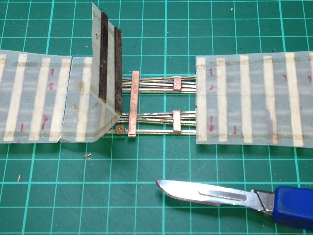 I then do exactly the same to the other side, but leave the centre full length piece of copperclad intact whilst the superglue and chairs set fully 982_260235_590000000.jpg 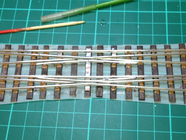 The half chairs that are fitted are super glued to the rails for added strength and glued using solvent to the sleepers, as I said I now let everything set thoroughly before repeating the process on the final copperclad strip I use the C&L 0.5mm strip out of convenience, any piece of strip metal 0.5mm thick or less would do. You could also use the strip between the sleepers so all chair parts are used, I feel this would look more visible than the method I have used |
||
| Attachment: attach_1998_2577_points_107.jpeg 522 | |||
|
posted: 26 Nov 2014 21:25 from: Trevor Walling
click the date to link to this post click member name to view archived images |
HelloJohn, That is quite a neat idea. Regards Trevor. |
||
|
posted: 26 Nov 2014 22:01 from: Hayfield
click the date to link to this post click member name to view archived images |
Trevor Hi You don't have to use copperclad strip, as any metal shim will work. Neither will there be any insulating gaps. The full length copperclad strip in the middle is there only for the duration of the initial build, and gapped electrically only for testing. It will be cut back to the rail sides as the other 4 bits were, as now the two K crossings are locked in position by super gluing the other 4 copperclad strips (and what will be the two central pieces)plus the chairs will also do their job of keeping the rails in position maintaining the gauge in the centre of the crossing The common crossings are insulated with plastic fishplates from the crossing rails, so electrically there are 4 areas insulated from each other. The chairs hold the rail 0.5mm above the sleeper, which is the same as the thickness of the copperclad. You could use brass or nickel shim (from etched kits), normally this is a bit thinner than 0.5mm but works equally well. I will post a photo of the next step once I do it, should make it much clearer |
||
|
posted: 26 Nov 2014 23:11 from: Trevor Walling
click the date to link to this post click member name to view archived images |
Hello, I was referring to insulation gaps to accommodate the changing polarity of different routes.I imagine those gaps in conjunction with representation of prototype rail gaps will be quite complex at times. Regards. |
||
|
posted: 27 Nov 2014 07:17 from: Hayfield
click the date to link to this post click member name to view archived images |
Trevor Sorry misunderstood, the only insulation gaps required atr those to the common crossings, as I said I use plastic fishplates by Exactoscale, other gaps are just notched with etched fishplates. The copperclad strips convey power to the crossing rails As it happens there are 4 electrical areas, two are the stock rails which remain constant. The other two are the common crossings which vary according to which route is taken. Just think they are back to back turnouts and wire accordingly |
||
|
posted: 27 Nov 2014 09:30 from: John Shelley
click the date to link to this post click member name to view archived images |
Hayfield wrote: TrevorAt the risk of being accused of blowing my own trumpet could I point (sorry!) you to some of my web pages where I show how some formations can be wired and the effect of going from one route to another is shown. The info is also downloadable as a pdf from each page. http://www.stciers.me.uk/home/track_wiring/pointwiring.htm Cheers for now John from 33820 St Ciers sur Gironde edit: broken link fixed. Martin. |
||
|
posted: 27 Nov 2014 18:57 from: Hayfield
click the date to link to this post click member name to view archived images |
John I always refer folk to the C&L website which has your wiring diagrams. My builds differ ever so slightly from your plan, as I make the insulation gap much nearer the common crossings. For ease of build and to maintain the natural flexibility of a one piece switch rail |
||
|
posted: 28 Nov 2014 09:28 from: John Shelley
click the date to link to this post click member name to view archived images |
Hayfield wrote: JohnThanks, I must admit that I'd forgotten that the pdfs were on the C&L site. Since then I've made my own pages "animated" to show how things change when the route selection is altered. Certainly the physical position of the insulation gap can move without changing the principles, I think that I chose the positions almost at random, maybe I should add a note to my pages about that, thanks for giving me the info and idea. Cheers for now, John, from 33820 St Ciers sur Gironde |
||
|
posted: 28 Nov 2014 19:31 from: Hayfield
click the date to link to this post click member name to view archived images |
John Its just the way I build them (single slips and diamonds), as I find it much easier the make the switch blades from one length of rail. So the easiest place to make the isolation break is the foint from the common crossing. Having said that on double slips I now make hinged switch blades (again from a single piece of rail fashioned at both ends and shaped first) but use a cast metal fishplate as the hinge, still isolating at the common crossing joints. The cast fishplate is far stronger than the plastic ones which would be usless for this application. Needless to say others may have their own methods |
||
|
posted: 29 Nov 2014 07:28 from: Hayfield
click the date to link to this post click member name to view archived images |
The last couple of photos of the build 982_290202_130000000.jpg 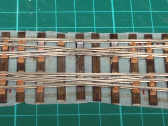 Here you see I have cut and filed back the central copperclad strip to the rail sides, then stuck the 2 parts to the sleeper. Another benefit of making both switch rails from 1 piece of rail and insulating the crossing at the common crossings is that it keeps the electrics simple, no need for either electrical bonding or dropper wires other than one for each common and obtuse crossing. 982_290203_060000000.jpg 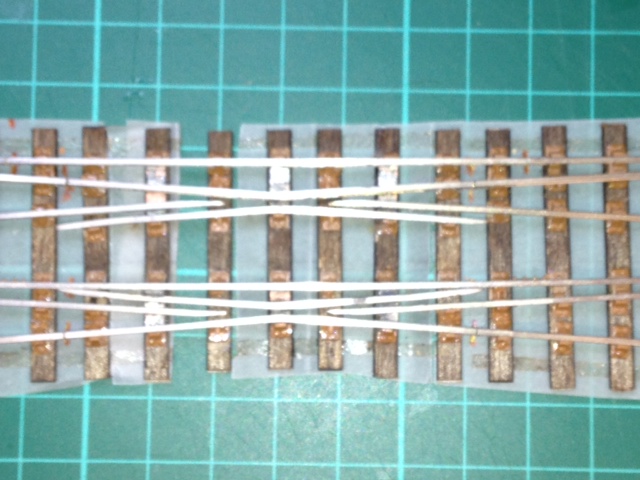 The cosmetic chairs have now been fitted, you can see that the copperclad strips are visible, a quick bit of paint will hide them. I will try and reduce the thickness of the central parts of the block chairs from either one of the crossing sprue's or another, just to add a bit more detail. As I have said they are designed for the P4 Company kits in P4 and to their design Its well worth using these packs, even if the plan you are using differs in size slightly. A few years ago I had a chat with Len and he said that the packs are quite versatile. So if you have a 1;6.5 crossing then see how the 1:6 fits then try the 1:7 combination. I have used the 1:7 slip chairs for a 1:6 slip and the fit was not to bad. Don't forget most of the crossing chairs come in 2,3 or even 4 parts and thats its the copperclad strip that holds all in gauge |
||
| Last edited on 29 Nov 2014 07:31 by Hayfield |
|||
| Please read this important note about copyright: Unless stated otherwise, all the files submitted to this web site are copyright and the property of the respective contributor. You are welcome to use them for your own personal non-commercial purposes, and in your messages on this web site. If you want to publish any of this material elsewhere or use it commercially, you must first obtain the owner's permission to do so. |