Templot Club Archive 2007-2020
|
|||
| author | remove search highlighting | ||
|---|---|---|---|
|
posted: 12 Feb 2018 22:13 from: madscientist click the date to link to this post click member name to view archived images |
IN the past when I used SCARM, for PECO orientated layouts , I found it fast and handy to use the "symbols-polygon " to draw baseboards overlaid onto my track plan. This then allowed me to see what size baseboard pieces would suit ( for portable layouts ) consistent with having no points crossing baseboard boundaries etc Then typically I drew the plywood sheet size and could visually place ( a copy ) of the baseboards into the ply sheet to maximise the sheet use Of course like a lot of things in SCARM , the "precision " of the results is not the best , as you cant specify polygons by numeric input , so you get a lot of 47.96 inch baseboards ! Now on Templot I have traditionally exported the track plan to my 2D CAD package ( Draftsight ) and then proceeded to compute the baseboards in that package The only issue there is the rather laborious to-ing and fro-ing when I need to modify the track templates where I discover baseboard boundary issues I have used the background shapes features in Templot and they are great , the main issue is the lack of polygon drawing I know its possible to import a DXF background shape , but havent tried that yet I also know the sketchpad can be used but I dont find that as good as the background shapes any suggestions ?, It would be " Nice" to be able to draw and edit multi sided polygons as background shapes or maybe I'm missing a way to do it easily in Templot thanks as always Dave |
||
| Last edited on 12 Feb 2018 22:17 by madscientist |
|||
|
posted: 12 Feb 2018 22:39 from: Martin Wynne
click the date to link to this post click member name to view archived images |
madscientist wrote:any suggestions?, It would be " Nice" to be able to draw and edit multi sided polygons as background shapes or maybe I'm missing a way to do it easily in TemplotHi Dave, Do it on the sketchboard, and then have the sketchboard items showing on the trackpad. Jumping to and fro is only one click each way. The background shapes functions are so primitive it's embarrassing. They were originally created, sometime in the last century, to draw a single rectangle around the track plan. I have kludged various other options onto them, and I'm about to do more. But polygons other than rectangles are out, there just isn't any means to do it within the BGS file format. All legacy BGS files would fail if I change it. The sketchboard was intended to replace them entirely, but it didn't work out. The main reason being the picture shapes and scaled maps. Those need splitting out into a separate format, but not yet because I have too many other things to do. I have re-written the picture shapes already about 17 times because everyone said they were too difficult to follow. cheers, Martin. |
||
|
posted: 12 Feb 2018 23:45 from: madscientist click the date to link to this post click member name to view archived images |
thanks martin , Ill experiment more with Sketchpad. At present the DXF export is manageable , as long as I dont get into too many iterations of track to DXF regards dave |
||
|
posted: 13 Feb 2018 13:16 from: Tony W
click the date to link to this post click member name to view archived images |
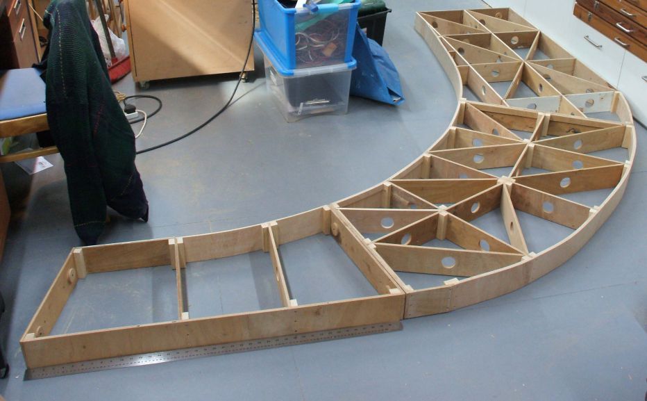
Hi Martin. The background shapes may be basic and primitive but in combination with track centre lines and a bit of ingenuity, it is surprising what can achieved. I have designed and constructed some nice curved baseboards for the ends of Brimsdown, well designed in detail and constructed one set so far as I seem to be otherwise occupied at the moment. The use of track centre lines in particular for curved sections of baseboard edge allows the precise lengths and joint angles to be calculated. As a friend of mine once observed, Templot works to 32 bit precision. Shame my woodwork doesn't. 0.25mm is about as good as it gets with a similar degree of accuracy when cutting angles on the band saw. I was the one in woodworking class who's mortise and tenon joints parted company when picked up by the woodwork master. It is also possible by duplicating the background shape lines with track centre lines to rotate them as part of a group along with your track templates. I know this can't include picture shapes, but is a partial work around that I have used more than once to rotate baseboard joints around an angle with the track templates prior to printing a section of trackwork. Just remember to disable the background shapes in the print list first or they can confuse the picture. Regards Tony. |
||
|
posted: 13 Feb 2018 14:04 from: Martin Wynne
click the date to link to this post click member name to view archived images |
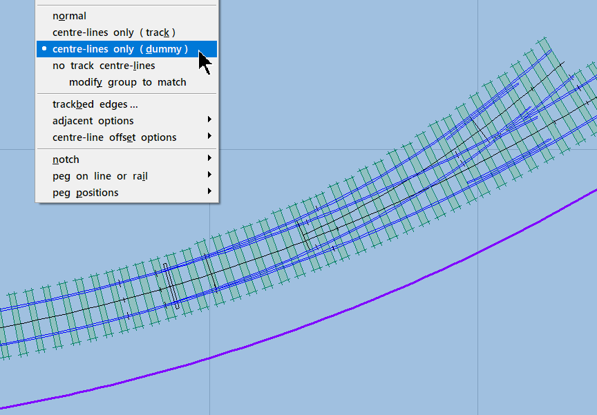
Tony W wrote:The background shapes may be basic and primitive but in combination with track centre lines and a bit of ingenuity, it is surprising what can achieved.Hi Tony, Indeed. The operative words there are "a bit of ingenuity". But ingenuity isn't always in plentiful supply. And it doesn't read well to start a reply to a question with "Yes, with a bit of ingenuity, ..." which is often taken as code for "No, not really". I remember before the sketchboard was introduced, suggesting that buildings and other structures could be represented as shoved bonus timbers. It was laughed at as a serious suggestion, but it actually worked very well. And for items such as a cattle dock or engine shed, it had the advantage that they moved with the track if it was modified or repositioned. Using dummy templates for curved baseboard edges is an established method, and there is even an option to display them in the same style as the background shapes: 2_130853_390000000.png  which can get confusing if you forget that they are not actually in the BGS file. p.s. Templot works to 80-bit (10-byte) extended precision for the track design. That's how straight track can be represented as a radius of 62 miles (in the model) and still work in the curve calculations. The sketchboard engine uses 32-bit precision. cheers, Martin. |
||
|
posted: 14 Feb 2018 22:28 from: Tony W
click the date to link to this post click member name to view archived images |
Tony W wrote: Hi Martin.Here is a picture of some of the baseboard frames referred to whilst being checked for squareness. 2151_141732_070000000.jpg  Regards Tony. |
||
|
posted: 14 Feb 2018 22:55 from: Andrew Barrowman
click the date to link to this post click member name to view archived images |
It's a shame that won't be visible after you cover it up with track and stuff |
||
|
posted: 15 Feb 2018 00:31 from: d827kelly
click the date to link to this post click member name to view archived images |
One of the club layouts has angled mirrors so viewers can see the undergubbins of the layout. Primarily that is for showing the MERG modules and so on when explaining the use of it however. | ||
|
posted: 15 Feb 2018 10:01 from: madscientist click the date to link to this post click member name to view archived images |
How did you create curved baseboards using background drawing objects , there is no polygon ?? I like the baseboards by the way , mine are similar except the joints don't have blocks of wood , but are fibre glass taped and laminated with polyester resin I try to avoid diagonal support members if at all possible as they interfere with everything |
||
| Last edited on 15 Feb 2018 10:04 by madscientist |
|||
|
posted: 15 Feb 2018 11:11 from: Martin Wynne
click the date to link to this post click member name to view archived images |
madscientist wrote: How did you create curved baseboards using background drawing objects , there is no polygon ??Hi Dave, Tony used dummy track templates instead. That's what this menu item is for: 2_130853_390000000.png  (geometry menu) They are drawn in whatever style you currently have set for the background shapes. You can use all the track template functions to design them. cheers, Martin. |
||
|
posted: 15 Feb 2018 11:54 from: madscientist click the date to link to this post click member name to view archived images |
OK, thats interesting , I hadn't considered that Then these could be DXFed to extract overall board dimensions etc hmmmm..... |
||
| Last edited on 15 Feb 2018 11:55 by madscientist |
|||
|
posted: 15 Feb 2018 13:40 from: Tony W
click the date to link to this post click member name to view archived images |
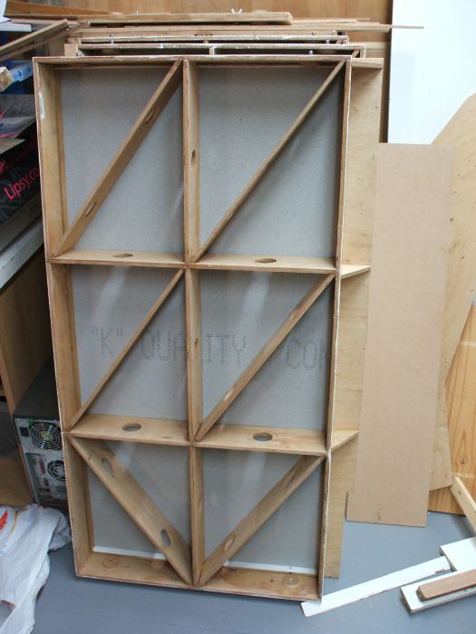
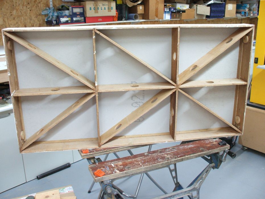
Hi Dave. The diagonals are there to stop the baseboards twisting. Without them there is little resistance to such forces. 2151_150754_590000000.jpg  2151_150751_480000000.jpg  As in the above examples, it is possible to vary where the diagonals go depending on where things are above board as from the Templot plan one can see where the turnout operating units will go and avoid these areas as much as possible. These are all fiddle yard boards. The scenic ones will be done differently. To generate a cutting list for each curved board, I print out each board scaled to fit one sheet of A4 paper as centre lines only. The lengths of the various members are worked out from the template lengths displayed in the information panel (when selected as control) or press the F4 key to display it. One just has to remember to allow for the thickness of the material in the right places. I write the full length outside the line and the required length inside whether different or not. The angles for the blocks on the curved boards are calculated by selecting the particular template centre line and moving the Peg to one end or the other of other as appropriate, note the peg angle. (Displayed toward the bottom of the list) Then select the one it joins up to and do the same. The angle of the join will be the difference between the two. You may occasionally have to add or subtract either 90 or 180 degrees to get a sensible answer. With the curved edges you may need to slide the peg along the centre line to reach the required point of the curve where the two elements meet. The diagonals were cut over-length and trimmed to fit. They only need to be a loose sliding fit as any force causes the baseboard frame to distort, as I learned the hard way. All the angles were cut using a band-saw with the table set to the appropriate angle. One also needs a large enough known flat area to assemble the thing on upside down. Regards Tony. |
||
|
posted: 15 Feb 2018 16:16 from: madscientist click the date to link to this post click member name to view archived images |
Hi tony , I've built several , using a similar method , where I tape all the joints with 2" fibreglass tape and then apply polyester resin , rather in the fashion you build a wooden dinghy I've tended not to use diagonals , yes you can get " some" twist a,on the length , but in reality I don't feel this is an issue as the boards sit on levelled trestles , longitudinal and transverse strength is superb , tested on a 5' by 3' board and a 9 stone man sitting on it while it's supported on its ends , no deflection could be detected ( 6mm birch ply ) I'm now about to build 18 baseboards for a new club layout and trying to avoid diagonals ?. |
||
|
posted: 15 Feb 2018 16:18 from: madscientist click the date to link to this post click member name to view archived images |
.thsnks tony How will the scenery boards be different ? Dave |
||
| Last edited on 15 Feb 2018 16:26 by madscientist |
|||
|
posted: 15 Feb 2018 16:47 from: Tony W
click the date to link to this post click member name to view archived images |
Hi Dave. The straight scenic boards (1500mm x 750mm) have a frame that is one inch shallower than the fiddle yard boards, (that's how they came, second hand) so the track bed will need to be an inch plus above this and be made as a separate item as in the Open frame system. This is not something I have tried before and have not finally made up my mind exactly how to tackle it yet. Still work in progress. There was once an article I saw entitled "In search of Z" which used this system. Not that there was much Z in the area I am modelling. Regards Tony. |
||
|
posted: 15 Feb 2018 17:17 from: Rob Manchester
click the date to link to this post click member name to view archived images |
Hi, There is some info here :- Increasing Torsional Stiffness altough it refers to welding rather than glue and screws Rob |
||
| Please read this important note about copyright: Unless stated otherwise, all the files submitted to this web site are copyright and the property of the respective contributor. You are welcome to use them for your own personal non-commercial purposes, and in your messages on this web site. If you want to publish any of this material elsewhere or use it commercially, you must first obtain the owner's permission to do so. |