Templot Club Archive 2007-2020
|
|||
| author | remove search highlighting | ||
|---|---|---|---|
|
posted: 10 Mar 2018 22:40 from: dave turner
click the date to link to this post click member name to view archived images |
Hi Martin, Before you scream, or throw your hands up in horror, about the subject please bear with me. One of the interesting things about XTraCad is that it appeared to allow for different levels in a model railway, particularly including vertical transitions. -Note that I'm not talking about the extreme gradients that Hornby Dublo, amongst others offered. My basic question is:- If Templot is used to create plans for a multi-level network how much 'fettling' would be required? For example I've observed that many large models use spirals to transition from one level to another. At sensible gradients could native Templot allow for a change in gradient? My suspicion is not, but how far out would one practically be? (Piece of string)? regards Dave |
||
|
posted: 11 Mar 2018 13:12 from: Martin Wynne
click the date to link to this post click member name to view archived images |
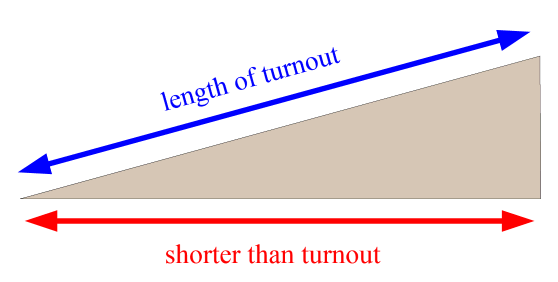
Hi Dave, Templot is neither 2D nor 3D. It is referenced to the rail top, so that the printed output can be used as a construction template. In other words, the length of a turnout is the same regardless of whether it will be laid horizontal or on a gradient. For a 3D representation it would need to be shortened in the 2D plan view if laid on a gradient, like this (gradient greatly exaggerated for clarity): 2_110741_270000000.png  Which would obviously make the 2D plan view useless for track construction (but correct for baseboard construction). While the above would be easy to do in Templot for inclined straight track, it gets more complex for the vertical curves top and bottom, and turns into a minefield for curved track and junctions. We are not going there. To create a true 3D representation I suggest exporting a DXF file from Templot, and making the corrections in a CAD package for the inclined tracks. In practice with the gradients in a typical finescale model railway the difference in length for a single turnout is barely perceptible, but it builds up for a long snaking gradient between levels, and especially for a helix spiral. I suggest that long tracks on a gradient are given a different marker colour, and saved separately as a group. So that you know when building them that length adjustments may be needed. cheers, Martin. |
||
|
posted: 11 Mar 2018 17:02 from: dave turner
click the date to link to this post click member name to view archived images |
Martin, Thanks for your reply. Your explanation is much as I had expected. I had no intentions of suggesting that Templot itself should be altered. Sadly personal circumstances preclude me having my own layout so I use Templot as an intellectual exercise. When the mood takes me I find much enjoyment using (wrestling with) it to create an imaginary layout or attempting to replicate an actual station. (Usually Shrewsbury) So lacking practical experience I was interested in finding out how much fettling would be required when translating the printed output from Templot to a layout that includes level changes. cheers Dave |
||
|
posted: 11 Mar 2018 20:14 from: Martin Wynne
click the date to link to this post click member name to view archived images |
dave turner wrote: So lacking practical experience I was interested in finding out how much fettling would be required when translating the printed output from Templot to a layout that includes level changes.Hi Dave, Here's a (much exaggerated) diagram showing what happens: 2_111450_350000000.png  The upper red line shows the templates as printed flat. When the template is cut through and laid up or down an incline to a different level, you end up with a small gap in the templates. In practice it is a tiny gap at sensible gradients. For example for a 1:80 incline to drop 75mm (6000mm long), the gap would be only 0.5mm. That's well within the tolerance for laying out paper templates over a distance of 6 metres. cheers, Martin. |
||
|
posted: 11 Mar 2018 20:43 from: dave turner
click the date to link to this post click member name to view archived images |
Hi Martin, From your reply to all intents and purposes there is negligible fettling required. I would assume however that one would avoid having turnouts and crossings located on a transition in elevation. Thanks again. Dave |
||
| Please read this important note about copyright: Unless stated otherwise, all the files submitted to this web site are copyright and the property of the respective contributor. You are welcome to use them for your own personal non-commercial purposes, and in your messages on this web site. If you want to publish any of this material elsewhere or use it commercially, you must first obtain the owner's permission to do so. |