Templot Club Archive 2007-2020
|
|||
| author | remove search highlighting | ||
|---|---|---|---|
|
posted: 28 Jan 2009 09:13 from: Martin Wynne
click the date to link to this post click member name to view archived images |
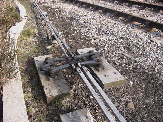
Something not often photographed -- rodding compensators. These are placed in runs of point rodding to convert a pull action into a push action. It's important that the total length of a rod connection in "pull" should be equal to the length in "push". This cancels out any movement at the far end caused by thermal expansion along the way. Often pulls can be converted to pushes where the rodding passes through angle cranks to cross under the rails, and this determines the exact location of such a side swap. Where equality can't be achieved that way, compensators such as these are inserted in the rodding run: 2-throwrods.jpg  © Neil Fraser Image linked from an interesting page of switch details and detection gear at a ground frame -- click the small images: Side-tracked . Martin. |
||
|
posted: 28 Jan 2009 09:33 from: Martin Wynne
click the date to link to this post click member name to view archived images |
I wrote: It's important that the total length of a rod connection in "pull" should be equal to the length in "push".p.s. That assumes of course that the entire rodding run is likely to be at the same temperature. If part of it is in a tunnel or similar location where ambient temperatures tend to remain constant, some further calculations are needed. Nothing is ever simple. Martin. |
||
|
posted: 3 Mar 2009 23:39 from: Jamie92208 click the date to link to this post click member name to view archived images |
Point rodding if modelled adds greatly to a layout. I put it in on my Long Preston 7mm layout non working but correctly designed using a 1920's signalling design manual that gave all the formulea for where to put the compensators. All the relavent pieces are available from C & L as lost wax castings. As mine was set in 1923 I used round brass wire to represent the round gas pipe that the Midland used in those days before the LMS adopted the later U shape that didn't rust as quickly. It was a fiddly job but Russell Whitwam installed it all and it looks good. Jamie Guest Martin Wynne wrote: Something not often photographed -- rodding compensators. These are placed in runs of point rodding to convert a pull action into a push action. It's important that the total length of a rod connection in "pull" should be equal to the length in "push". This cancels out any movement at the far end caused by thermal expansion along the way. Often pulls can be converted to pushes where the rodding passes through angle cranks to cross under the rails, and this determines the exact location of such a side swap. Where equality can't be achieved that way, compensators such as these are inserted in the rodding run: |
||
| Please read this important note about copyright: Unless stated otherwise, all the files submitted to this web site are copyright and the property of the respective contributor. You are welcome to use them for your own personal non-commercial purposes, and in your messages on this web site. If you want to publish any of this material elsewhere or use it commercially, you must first obtain the owner's permission to do so. |