Templot Club Archive 2007-2020
|
|||||
| author | remove search highlighting | ||||
|---|---|---|---|---|---|
|
posted: 26 May 2015 16:39 from: madscientist click the date to link to this post click member name to view archived images |
I'm progressing with building my Templot track layout of Claremorris in Ireland circa 1975-85. This will be all bullhead on wooden sleepers. I dont want to go to 21mm, as theres too much plain track to build ( and stock to convert) , so have decided to use 00-SF. its a decision I didn't take lightly what would people now consider as the pre-eminent way to build 00-SF points ( I will use C&L for plain track ) . (a) Copperclad with half chairs ( using vero pin to raise rail ) (b) Brook-Smith , again with half chairs on ply (c) all plastic construction ( how do we handle the lack of flange chairs etc ) (d) ply and plastic chairs , again we have a lack of crossing chairs for 00-SF (e) Combinations Paticulary as copper clad is getting more and more expensive and actually looks like it will exceed the cost of ply sleepers any day now. I expect Martin has a lot of views on this |
||||
|
posted: 26 May 2015 17:30 from: Nigel Brown click the date to link to this post click member name to view archived images |
I use all plastic in 3mm/ft. I carve up existing chairs to make different types. Works in 3mm. Depends on how keen you are on strict attention to detail, and also how suitable C&L chairs for adapting. | ||||
|
posted: 26 May 2015 17:31 from: madscientist click the date to link to this post click member name to view archived images |
Nigel Brown wrote:I use all plastic in 3mm/ft. I carve up existing chairs to make different types. Works in 3mm. Depends on how keen you are on strict attention to detail, and also how suitable C&L chairs for adapting. can that work to make flange way chairs etc. Given I cant get 1mm spaced chairs for 00-SF. how do I secure the common crossing vee in al all chair method, ( I notice several people solder metal bridges to over come this ) |
||||
|
posted: 26 May 2015 19:03 from: Martin Wynne
click the date to link to this post click member name to view archived images |
madscientist wrote:I expect Martin has a lot of views on thisNot really. I'm not fully up to date with the current supply position. John (Hayfield) on RMweb seems best placed to advise. For myself I much prefer all-soldered construction. Partly for the instant set and ease of adjustment, but also because I can't stand the pong of butanone. I think Joe Brook-Smith's original riveted ply system still has a lot to be said for it. The Scalefour Society have just upgraded their supplies to precision laser-cut plywood instead of sheared strip. The great advantage of riveted ply is that you can get the track built, laid, tested, wired up and running, and only later add the cosmetic half-chairs at your leisure. If the rivet positioning is done carefully, the end result looks just the same as using glued chairs on plywood. Beginners can deal with any misplaced rivets by fettling them with the edge of a Dremel abrasive disc. Fitting the rivets to the timbers can be time consuming, but strangely satisfying. An alternative to the tubular rivets is to used single-sided Vero pins. These are a push fit in 1mm holes, so don't need closing underneath and can therefore be drilled and fitted with the timbers on the template. But they do need trimming underneath afterwards. I doubt they would hold in plywood, but are fine in copper-clad or unclad SRBP laminate (their intended purpose). If double-sided copper-clad, remember to gap the underside too! Plain copper-clad with bullhead rail is acceptable to many, especially when painted. But you can't properly fit half-chairs because the rail is flush to the sleeper, unlike when using rivets or Vero pins to lift the rail clear of the sleeper in prototype fashion. regards, Martin. |
||||
|
posted: 26 May 2015 21:59 from: Nigel Brown click the date to link to this post click member name to view archived images |
Flangeway chairs: Lay running rail as normal. Pare off inside of chairs where the check rail is to go as much as you dare. Slide more chairs onto check rail. Pare off outside of chairs. Continue until the check rail will fit at the required spacing. Crossing V: I rely on the chairs further along the V to hold the V in position. A thin bit of V-shaped plasticard or similar (e.g. offcut from a slide chair) under the V nose supports the V; I add a dab of slow-setting superglue before laying the V, don't know if its effective but I haven't had trouble. You generally need to trim the outer faces of the chairs on the V (before laying the V) so that each pair will fit. Fitting the wing rail is similar to fitting the check rail. Crossing V alternative: Haven't tried this yet but may; it should be possible to build the crossing as a unit, then slide on most chairs and lay, one or two chairs may need to be cosmetic. The critical thing is whether the chairs you are using will take cutting about in this fashion. Nigel |
||||
|
posted: 26 May 2015 22:14 from: Hayfield
click the date to link to this post click member name to view archived images |
I spoke with Peter at the Railex show at the weekend and a new supplier has been found, with specification (and I guess a price) confirmed how long it will be before stocks are available should not be too long. With the cost of copperclad rising the cost differential between ply timbers and chairs against copperclad is very close, plastic timbers are slightly more expensive. Now anybody thinking about sticking chairs to copperclad sleepers will be entering a very expensive method of building trackwork. I do look at those who still built track using the Brook-Smith method of riveted trackwork admiring their building skills. But life has moved on since the 70's, punching holes into sleepers and timbers weakens them, solder joints fail, most rivets are wider that the rail foot. Half chairs fall off over time as do solder joints from the effects of expansion and contraction. For most applications plastic chairs will hold the rail firmly to the sleepers and timbers, and allow for expansion and contraction. Common and obtuse crossings can either be made as self contained units on 0.5 mm shim or copperclad. Or if prefered use copperclad sleepers where the crossing is, use shim or thin copperclad strip to raise the rails, some may feel this is an easier construction method. Once soldered in place grind the material back to the rail sides to allow the fitting of half chairs Who needs 1 mm check rail chairs for 00sf or EM gauge turnouts and crossings. In P4 they are a pain to thread, its far easier to cut a half chair off and fit the check rail using a check rail gauge. I will post a couple of photos which will explain the method. Sorry for those who prefer more traditional methods of turnout construction and feel I may be having a go at their methods, but the C&L/ Exactoscale and Peco plastic chairs have proved themselves now for over 30 years. Just use the correct solvents. Word of caution over the thin plastic sleepers/timbers, they curl up due to the solvent drying and shrinking on one side only. Either stick them down well or use either ply or the thicker plastic sleepers |
||||
|
posted: 26 May 2015 22:19 from: Rob Manchester
click the date to link to this post click member name to view archived images |
Hi John, You mentioned about the thinner plastic sleepers curling after having solvent applied on one side. Is this noticeable within a short period of time or does the effect lay dormant and hit you later ? I was thinking of the situation where you were building track at the workbench and then laying it onto the layout boards in sections. Rob |
||||
|
posted: 26 May 2015 23:22 from: Hayfield
click the date to link to this post click member name to view archived images |
undefined 982_261814_030000000.jpg 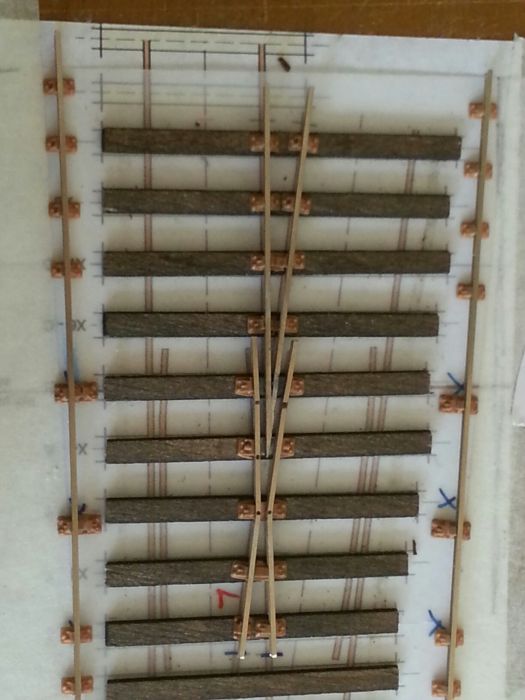 undefined 982_261815_170000000.jpg 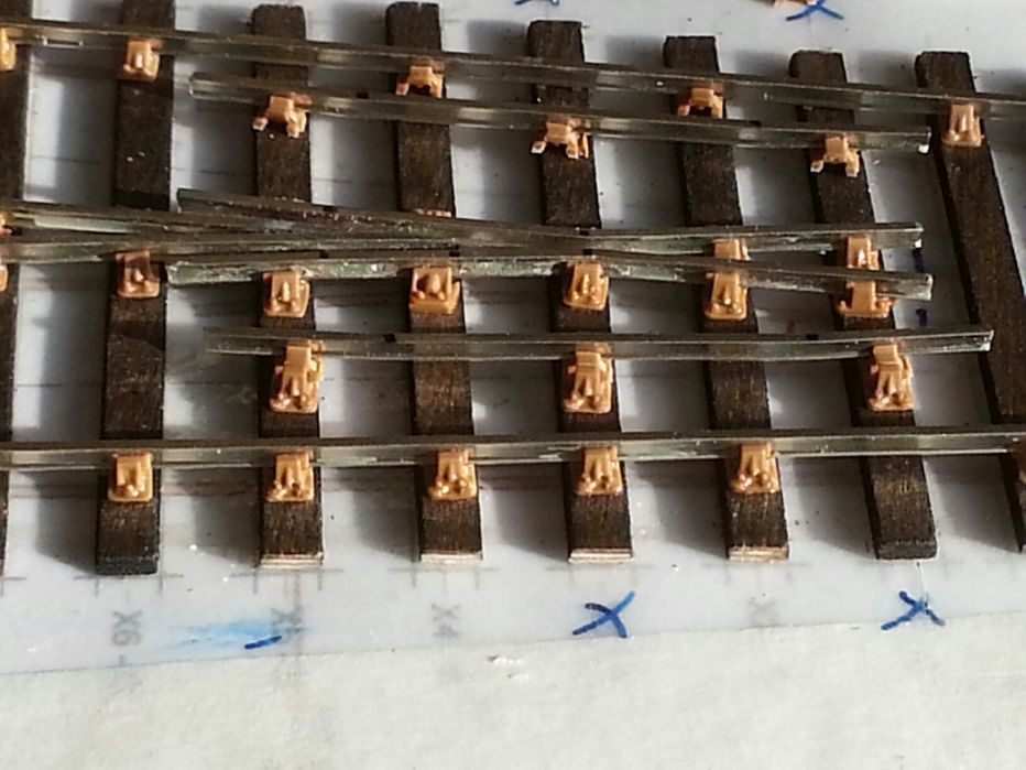 Here you see the check rail with the 3 chairs on and with their half chairs cut off. 982_261816_210000000.jpg 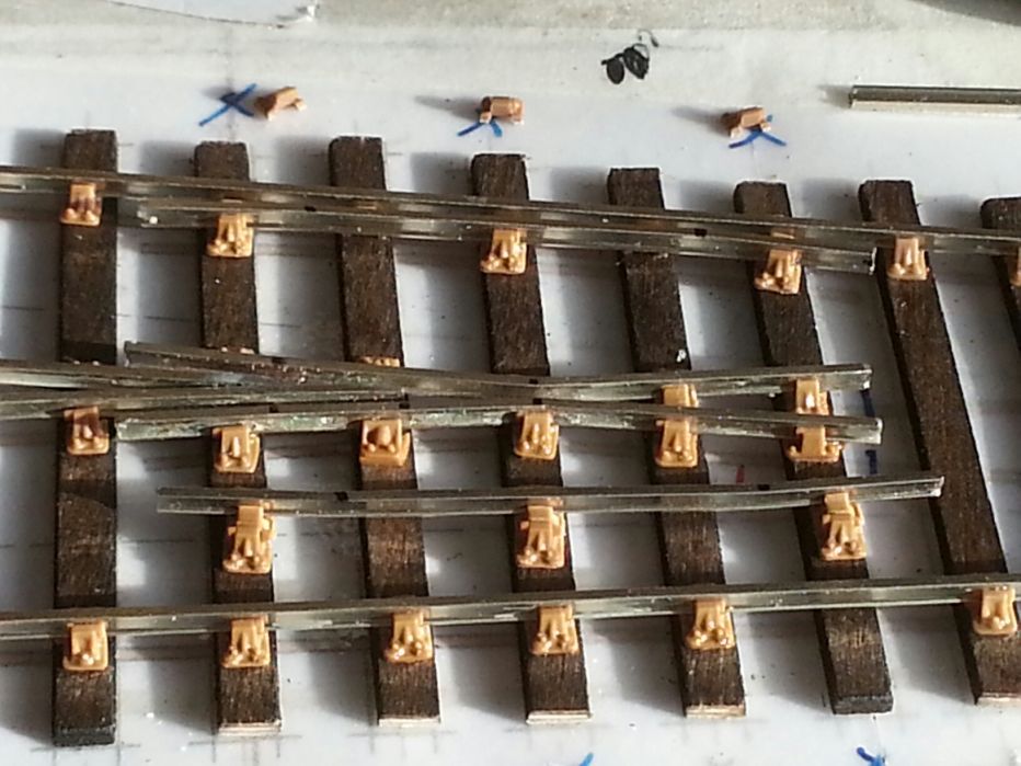 Now its slid into place using a check rail gauge, once set glue the half chairs in place. See also on RMweb: http://www.rmweb.co.uk/community/index.php?/topic/96646-we-have-a-problem-houston%E2%80%A6particularly-if-you-build-copper-clad-track/page-3#entry1902330 |
||||
|
posted: 27 May 2015 00:30 from: Martin Wynne
click the date to link to this post click member name to view archived images |
Hi John, I've added your images for you. Are you using Internet Explorer? It needs Compatibility Mode on to work here on the image buttons I'm afraid. I'm sorry about that, it's just too much work to keep up with Microsoft's changes. To insert images from the Gallery, click them to display the normal size image, right-click on it to get the image URL, paste it into your message inside
tags, like this
The same method works for Safari. regards, Martin. |
||||
|
posted: 27 May 2015 00:34 from: Nigel Brown click the date to link to this post click member name to view archived images |
Re my earlier comment, here's a pic I took part way through building a turnout to test the 3mm Society's then new plastic chairs: 528_261930_140000000.jpg 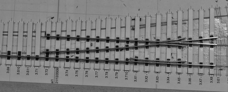 It should be fairly easy to see which chairs have been chopped where; you can even see some of the bits chopped off It should be fairly easy to see which chairs have been chopped where; you can even see some of the bits chopped off Sorry about the B&W; it was intended for a monochrome page of the Society magazine. The sleepers are Plastruct strip. Nigel |
||||
|
posted: 27 May 2015 07:48 from: Hayfield
click the date to link to this post click member name to view archived images |
Nigel The good thing about the Exactoscale range in 4 mm scale is that they have a range of additional chairs, admittedly for LMS/BR but most can be used with other regions. Bridge and small chairs for when rails converge, check chairs, common and obtuse crossing chairs, slip and additional switch chairs all make up a range which saves chopping chairs In 7 mm scale sadly from C&L and Exactoscale there are only the standard, slide and bridge chairs available, another range is slowly being created in 3D printing via Shapeways, I have been of a mind to buy some but always have held back, mainly due to cost. I will bite the bullet at some point as they do look stunning and 7 mm scale will really show them off |
||||
|
posted: 27 May 2015 08:24 from: Hayfield
click the date to link to this post click member name to view archived images |
Rob Manchester wrote: Hi John,Rob Sorry for the delay in replying I think this has been a problem known by the founder of both ranges for some time, as a thicker pack of turnout timbers were introduced into the C&L range and Exactoscale have never had thin plastic sleepers, and their version of the flexi track has thick sleepers which to my mind look and feel far superior than C&L and SMP ranges The plastic sleepers do curl up over time if not firmly stuck down, my educated guess is that its the effect of the solvent drying out and shrinking on one surface only, this seems not to happen to the thicker timbers or ply. Using a weaker solvent that Butanone may reduce the effect, another thought is to dab the reverse of the timbers with solvent opposite the chairs so you have equal forces on both sides. Another method which has been suggested is to gently heat the turnout so that it softens and lays flat again (may be high risk) When using them I advise making sure that both ends of the timbers are glued to the track bed and I guess glued to something like cork rather than my preferred underlay of closed cell foam and an impact adheasive If you want to go down the road of thin sleepers use ply and make sure the solvent you use is Butanone, I also use spirit based stain thinned down and applied first to the long strips by brush and allowed to dry off before use. For anyone starting out I would strongly recommend using the thicker sleepers/timbers including using the Exactoscale fast track bases. For the novice plastic timbers will be easier and the Exactoscale point and crossing timber pack being vastly superior as it has enough material for 2 turnouts, longer timbers than the C&L own brand and one 14" crossing nose timber. For the inexperienced builder you can use copperclad timbers in and around the crossings which is an easier build method, but do use spacers to lift the rail so not only do they remain at the same level but chairs can be used. Its far easier if you cut and fill the isolation gaps prior to fitting as they are much easier to sand flat. In fact it is also an easier method for the experienced builder, lending its self certainly to the plastic timbers more than the ply ones. This method also works with ply construction, just choose the correct thickness of PCB. Perhaps making some subtle grain scratches with coarse gritt |
||||
|
posted: 27 May 2015 08:38 from: Hayfield
click the date to link to this post click member name to view archived images |
Martin Thank you, I will try your suggested method. |
||||
|
posted: 27 May 2015 08:48 from: Hayfield
click the date to link to this post click member name to view archived images |
undefined Sorry for being thick but where is the paste button please or rather whats is the short cut keys to paste please |
||||
|
posted: 27 May 2015 09:45 from: madscientist click the date to link to this post click member name to view archived images |
Interesting. How does ply construction( ply plus functional plastic chairs ) match up with smp or c&l plain track ? So would the consensus be ( for turnouts construction) (A) thick plastic sleepers and mod chairs as required for 00-SF (B) A above but substitute copperclad at various strong points with rail rail lifted by shims or vero pin method (c) ply with plastic chairs , modded as neccessary for 00-SF ( D) as above with either copperclad or perhaps rivets at strong points |
||||
| Last edited on 27 May 2015 09:47 by madscientist |
|||||
|
posted: 27 May 2015 10:06 from: Hayfield
click the date to link to this post click member name to view archived images |
Pack up the flexitrack with thin card/cork/plastic to the same height or use thicker base flexitrack Punching holes in ply weakens the sleeper/timber, if you want to solder use copperclad Use whichever method you feel easier with not what others suggest For novices I would advise the use of copperclad sleepers for an easier building method |
||||
|
posted: 27 May 2015 11:38 from: Charles Orr
click the date to link to this post click member name to view archived images |
Hi All, This topic has cropped up at just the right time as I need to make a similar decision on the method of track construction I will finally adopt. In the past I have built turnouts using the straight soldered to copper method. I would like to progress to a method that allows the rail to be lifted above the timbers and then chaired as discussed above. Plastic chairs and sleepers seems a possible way but I do like the strength of soldered track. I have seen the vero pin method mentioned elsewhere and I would welcome some guidance on its use. Presumably a 1mm hole needs to drilled in the copperclad timber and the pin inserted? What would be the best way of locating the holes accurately? The vero pins I have seen are quite long so presumably would need to be shortened and then pushed into the hole so that the flat top is flush with the top of the timber. Soldering the rail then fixes both securely. Check rails are similarly fixed. Using Vero pins how are the slide chairs implemented for the switch rails? What do the switch rails slide on? I can support the crossing vee using copper shim to lift it to the correct height. As Martin has already pointed out, the cosmetic chairs can then be added later. Thanks for any help you can provide. Charles |
||||
|
posted: 27 May 2015 11:49 from: Martin Wynne
click the date to link to this post click member name to view archived images |
Hayfield wrote: undefinedHi John, Right-button-click and select Paste on the menu which appears, or alternatively press CTRL+V keys. regards, Martin. |
||||
|
posted: 27 May 2015 12:25 from: Paul Boyd
click the date to link to this post click member name to view archived images |
Can I throw in another method? Copperclad timbers with Masokits chairs. This certainly gives very robust results and looks really good from normal viewing distances. There's some photos on my Shotley album here 105_020532_490000000.jpg 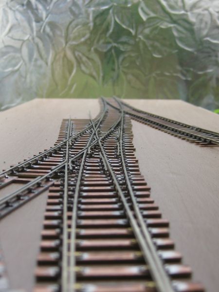 (Wonder if that image will show - Chrome will no longer let me insert images from the gallery!) |
||||
|
posted: 27 May 2015 12:55 from: Hayfield
click the date to link to this post click member name to view archived images |
[img]gallery/982/thumbs/982_270341_530000000.jpg [/img] Why bother with drilling then cutting pins to length, make spacers with either 0.5 mm metal strip or double sided copperclad strip, the latter will automatically insulate the rail from the sleepers [img]gallery/982/thumbs/982_270342_400000000.jpg[/img] Grind the surplus material level with the rail sides and glue on half chairs. Keep things simple, less to do and go wrong Well I tried to post the photos |
||||
| Last edited on 27 May 2015 22:43 by Hayfield |
|||||
|
posted: 27 May 2015 13:51 from: Martin Wynne
click the date to link to this post click member name to view archived images |
Charles Orr wrote: I have seen the vero pin method mentioned elsewhere and I would welcome some guidance on its use.Hi Charles, It is getting on for 40 years since I last did this. It worked fine then, so there's no reason why it shouldn't work now. But as far as I know no-one has recently tried it, or at least, they haven't said so. Very briefly: Vero pins available here (and elsewhere): http://uk.rs-online.com/web/p/terminal-posts/6319596/ Drawing of Vero pin here: http://docs-europe.electrocomponents.com/webdocs/0e57/0900766b80e578ba.pdf 1. attach the template to a softish workboard which can be drilled into easily. 2. fix the timbers on the template in your usual way. 3. print from Templot a drilling guide on tracing paper, and fix it over the timbers. See below. 4. drill 1mm holes on the marks, through the timbers and into the base. (7mm, 1/4", deep). 5. remove the drilling guide and push in Vero pins firmly. They have ribs under the head to hold firm in laminate. A gentle tap with a toffee hammer might help to seat them all level. 6. solder the rails on top of the Vero pins, in the same way as Brook-Smith rivets. They are already tinned which helps. 7. carefully prise up the finished turnout from the workboard. 8. trim the protruding pins flush on the underside. (e.g. Xuron rail cutter, eye protection). 9. some could be left protruding for invisible electrical connections. (I would be wary about that, physical fixings don't always make reliable electrical connections. A wire directly to the rail will work for 50 years in all conditions.) • If using double-sided copper-clad, remember to gap the underside. 10. the Vero pin heads are smaller than Brook-Smith rivet heads, so fitting of cosmetic half-chairs is easier. Here's a typical drilling guide on tracing paper, rail centres over timber centres: 2_220711_090000000.png 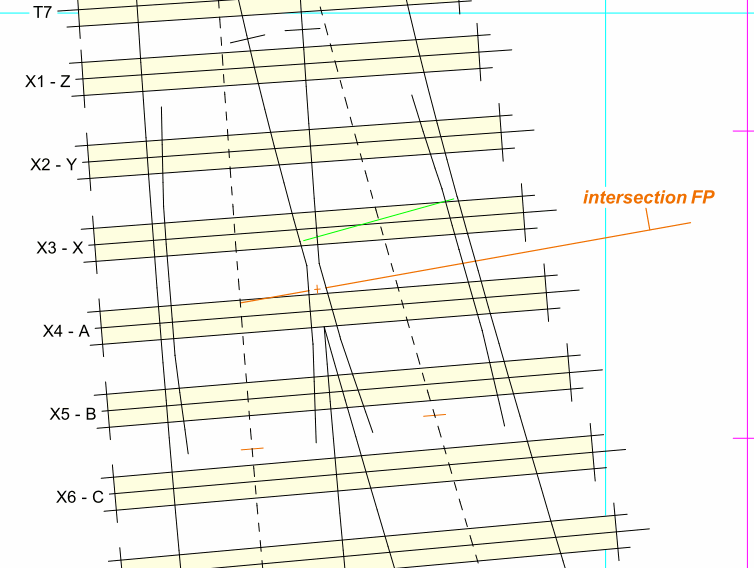 See the bottom of this page for how to print it: http://templot.com/martweb/gs_printing.htm More about all this here, and other topics on RMweb: http://www.rmweb.co.uk/community/index.php?/topic/88849-horrabridge/page-5#entry1560435 regards, Martin. |
||||
|
posted: 27 May 2015 14:14 from: Charles Orr
click the date to link to this post click member name to view archived images |
Hi Martin, Many thanks for that comprehensive advice. Best regards Charles |
||||
|
posted: 27 May 2015 14:28 from: Martin Wynne
click the date to link to this post click member name to view archived images |
Hayfield wrote:Well I tried to post the photosHi John, You didn't type the img tags around the URL:
I'm sorry it is so difficult for you, which browser are you using? I just tried Internet Explorer 11 and the normal buttons work fine. 982_270341_530000000.jpg 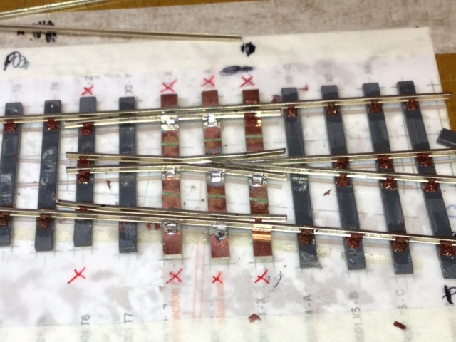 982_270342_400000000.jpg 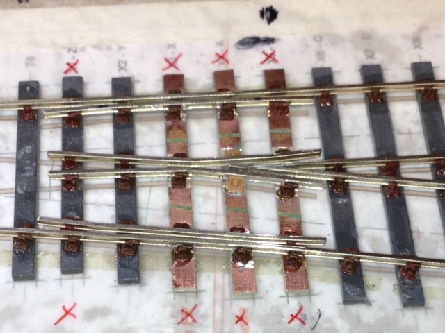 Martin. |
||||
|
posted: 27 May 2015 23:36 from: madscientist click the date to link to this post click member name to view archived images |
Paul Boyd wrote:Can I throw in another method? Copperclad timbers with Masokits chairs. This certainly gives very robust results and looks really good from normal viewing distances. There's some photos on my Shotley album here very nice, in your ply and chairs versions, how did you support the "V" |
||||
|
posted: 28 May 2015 08:59 from: Paul Boyd
click the date to link to this post click member name to view archived images |
Hi "madscientist"very nice, in your ply and chairs versions, how did you support the "V" If I'm using ply timbers, I always make the vee assembly (and sometimes the whole crossing) off the template, and use strips of brass or nickel etch waste poking out the sides to take the wing rails. It's these bits of waste that are epoxied to the ply timbers: 105_280356_280000000.jpg 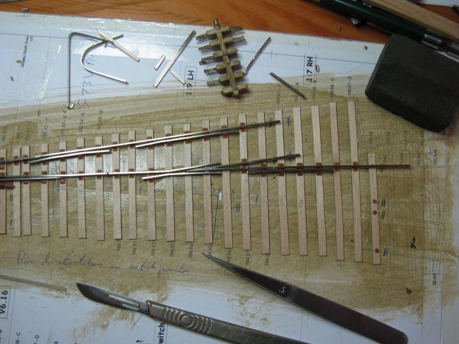 If you look closely between the vee and the wing rails you can see these bits of etch waste. Hope this helps! Paul |
||||
|
posted: 28 May 2015 10:31 from: Martin Wynne
click the date to link to this post click member name to view archived images |
Paul Boyd wrote: The gallery on this forum seems to be brokenHi Paul, I haven't changed anything, and it is all working fine here (Firefox and IE11). Which browser are you using? Unfortunately Google Chrome has become the new IE, with frequent changes and non-standard functions and behaviour. The reason your image didn't display is that the URL included a font tag inside the img tags:
How did you manage that? Here it is without that: 105_280356_280000000.jpg  regards, Martin. |
||||
|
posted: 28 May 2015 11:06 from: Paul Boyd
click the date to link to this post click member name to view archived images |
Hi MartinI haven't changed anything, and it is all working fine here (Firefox and IE11). Which browser are you using? Unfortunately Google Chrome has become the new IE, with frequent changes and non-standard functions and behaviour. The reason your image didn't display is that the URL included a font tag inside the img tags: [img]gallery/105/105_280356_280000000.jpg[/img] How did you manage that? Here it is without that: Umm..... I'm using Chrome! I've got no idea how the font tag got there! I copied the image URL, typed the img bit, pasted the URL then typed the closing img bit. It all used to work OK, but Chrome does keep being updated. I was a Firefox user but I found it was just getting too sluggish. Unfortunately Chrome is heading the same way as software developers keep fiddling with things for the sake of it, or more likely to justify their jobs! |
||||
|
posted: 28 May 2015 18:18 from: Trevor Walling
click the date to link to this post click member name to view archived images |
Hello,I was a Firefox user but I found it was just getting too sluggish.It could be the cache is too large2110_281317_570000000.png  Regards. |
||||
|
posted: 28 May 2015 23:39 from: Rob Manchester
click the date to link to this post click member name to view archived images |
Hello, It would be good if we had a comparison chart giving the types of track making 'methods' available and the pro's and con's of each method. People browsing the forum in the future would be aided by this, just reading all the ( helpful ) replies on here may tend to confuse. The chart could give a view on the strength, longlivity, cosmetic looks, ease of building, etc and could add comments specific to a method ( smell of the glue, hard to find parts or suchlike ). Any takers to compile one ? Two specific questions :- Are THIN plastic sleepers OK in the long term if properly glued to a firm substrate and what is considered a proper glue ? Is the curling problem worse on turnout timbers due to the extra lengths involved or better due there being ( in some cases ) more rails holding them down. Are Veropins always flat under the head or is there any irregularity in this area that could result in the heads not being the same height above each sleeper. Rob |
||||
|
posted: 29 May 2015 11:14 from: madscientist click the date to link to this post click member name to view archived images |
Hi rob , hard to make a comparison chart as no one person is building all methods. I'm currently examining a few so I'll try to. Build a cost matrix Vero pins are flat topped and regular , they are quite precise dimensionally Personally I am favouring a combination of methods with copperclad and vero pins at strong points |
||||
|
posted: 29 May 2015 13:18 from: Nigel Brown click the date to link to this post click member name to view archived images |
Hi Rob Think a chart would be difficult, as there are many imponderables. The advantage of raising the question on here is that you may receive new information. In building my 3mm layout I used mainly chairs from Ian Osborne with Plastruct 0.75mm thick sleepers and timbers, and using Plastic Weld (which smells OK, at least to me). Curling wasn't uncommon, but not really noticeable on plain track. The worst was on the longer timbers in pointwork, probably a factor of the number of chairs per timber. Where it mattered I drilled a hole near the ends of timbers and pinned it down with Peco track pins. I now use 3mm Society track bases (which include chairs) for plain track, and Society chairs on Plastruct 1.0mm thick timbers for point work. These thicker timbers don't seem to curl, or maybe I'm more sparing with the Plastic Weld. The Plastic Weld isn't quite as effective on the Society chairs, so at some point I'll try Butanone, which as yet unknown effect. The curling if present happens as the solvent dries. I've no evidence that it happens over a longer term. I stick track down with double sided tape, which will correct moderate curling. Ballasting then holds it down OK. Nigel |
||||
|
posted: 29 May 2015 16:56 from: Paul Boyd
click the date to link to this post click member name to view archived images |
Just as an aside re butanone, don't buy the hugely overpriced little bottles from model suppliers! I bought a much larger bottle for a lot less money from a supplier who advertises on eBay, and that includes delivery by courier (seeing as Royal Mail no longer want to be inconvenienced by delivering things any more!). Right now, you can get a 500ml bottle for £7.99 delivered, which seems pretty good to me and will last years and years. I decant it into a smaller jar for the bench. Search for either "butanone" or "methyl ethyl ketone". I seem to have shifted from railway modelling to plastic modelling and use this stuff exclusively, but I've also used it on plastic/ply track building. Hope this helps someone! |
||||
| Last edited on 29 May 2015 16:57 by Paul Boyd |
|||||
|
posted: 31 May 2015 08:22 from: Hayfield
click the date to link to this post click member name to view archived images |
There was an attempt to do costings on a parallel thread topic 2702 - message 18761 In summary for an A5 turnout Copperclad construction £4.04Copperclad construction + chairs £9.42Ply timbers & chairs £7.50Plastic timbers & chairs £9.66Using the additional special plastic chairs From £3.50 extra The copperclad costs were based on the old price, at a guess you could add another £2 to the costs, in fiddle yards this can be offset by using fewer timbers without affecting the strength of the turnout Rather than Vero pins, its far simpler to use either a piece of metal shim (scrap brass from a fret or buy 0.5 mm x 2 mm metal strip or better still use 0.5 mm thick copperclad for 4 mm scale )1 mm for 7 mm scale)) I see no benefit in either cost, strength or ease of build in using copperclad construction method for chaired turnout and crossing construction other than under common and obtuse crossings. Another tip is to pre gap and fill the copperclad timbers prior to fitting, its so much easier. If Vero pins are steel keep away, as those who used steel rivets in the ply & rivet method have found the steel rivets are now rusting. Also what is the head thickness, to my mind modern glassfibre double sided strip is so easy to use and work with The timber/sleeper curl affects the thinner plastic timbers & sleepers only, thicker plastic and ply timbers and sleepers are unaffected. From what I understand its the result of the solvent drying out and shrinking. Gluing both ends with a solvent based glue (Evostik etc) if not the whole length and sticking to a solid base (Cork etc not foam) is advisable I would strongly recommend using the thicker timbers/sleepers (1.6 mm) for stability reasons, even ply and the use of Exactoscale fast track bases which are also 1.6 mm thick to match. SMP and C&L use thinner track bases which to my mind are not as robust A weaker plastic solvent on plastic timbers may reduce the curling affect. But you need Butanone to stick plastic to ply, as some have reported problems using other makes where the bond is not as strong Another plug for C&L is the HiNi rail which is far less yellow in colour than normal nickelsilver rail Having said all this many folk have used the thin plastic sleepers and timbers very successfully over the years, and the strength of the plastic chair system is well proven. I have trouble up loading files (its me and Microsoft) to this forum, perhaps someone else could do a comparison chart |
||||
|
posted: 31 May 2015 11:23 from: Martin Wynne
click the date to link to this post click member name to view archived images |
Hayfield wrote:If Vero pins are steel keep away, as those who used steel rivets in the ply & rivet method have found the steel rivets are now rusting. Also what is the head thicknessHi John, Vero pins are tinned brass. It is many years now since the tinned steel rivets were available from Studiolith Ltd. The rivets from the EMGS or Scalefour Society are copper or brass. Measuring some 20-year-old Vero pins, the head thickness is 0.6mm. The required thickness would be 0.58mm to represent the base of chair castings in 4mm/ft scale (1.3/4" thick). The head diameter is 1.8mm. This is less than the 2mm Brook-Smith rivets, so makes fitting half-chairs a bit easier. F6319596-01.jpg  I have ordered some new Vero pins to measure current production. I can see that using bits of scrap kit fret or 0.5mm copper clad is cheaper, and doesn't require the drilling of holes. But it is surely difficult to cut them small enough and locate them accurately below the rail centre? Fitting of cosmetic half-chairs is dead easy if the rivets are in the right place -- just cut the chair in half, push it against the rail, flood with solvent*. And a real pain if they are not -- out with the Dremel to carve away at the rivet until the half-chair will fit. *on ply or basswood timbers. I'm not sure about sticking chairs to copper-clad? One of the cyano adhesives perhaps. regards, Martin. |
||||
|
posted: 31 May 2015 20:00 from: Hayfield
click the date to link to this post click member name to view archived images |
Martin Good evening, Scrap fret is cost free but normally but most times the wrong size. I have been informed that the C&L chairs lift the rail 0.5 mm above the timber I have tried 2 materials both of which work very well. Metal strip 0.5 mm x 2 mm and the double sided copperclad strip is 0.5 mm x 3 mm, both are very quick and easy to cut with wire cutters, both are very easy to solder to the copperclad timber and rail. The copperclad strip not only is easier to grind back to the rail sides with a slitting disc on a mini drill, but in addition isolates the rail from the timber, after using both materials copperclad is easier to grind back than metal strip I pre-tin both items which makes soldering that much easier, but I guess its just as easy/hard as the Vero pin method |
||||
|
posted: 31 May 2015 21:24 from: polybear click the date to link to this post click member name to view archived images |
Hi all, After martin mentioned the use of Veropins some weeks ago I thought I'd give them a try - see here: http://www.rmweb.co.uk/community/index.php?/topic/69145-attention-00-sf-track-builders/page-4 For me I'm really impressed with the idea - some of the photos are less than kind due to the use of the zoom lens, however the thread does point out some of the things to be aware of. Veropins are readily available; veropin "lookalikes" are also available (sometimes more cheaply) via Ebay - I've no experience of them but perhaps the quality/dimensions may be something to consider? If anyone does give them a go I'd be interested to know your views. All the best, Brian |
||||
|
posted: 1 Jun 2015 01:15 from: Nigel Brown click the date to link to this post click member name to view archived images |
Hayfield wrote: A question. Just been trying a different method of mounting pickups on a locomotive, using a gaped rectangle of copperclad bolted underneath the chassis. I used a slitting disc to cut the rectangle from a sheet of copperclad, and became a bit suspicious of the very fine dust which was being created. Any idea how safe this is? Cheers Nigel |
||||
| Last edited on 1 Jun 2015 01:59 by Nigel Brown |
|||||
|
posted: 1 Jun 2015 07:06 from: Alan Turner
click the date to link to this post click member name to view archived images |
Nigel Brown wrote: Hayfield wrote:A question. Just been trying a different method of mounting pickups on a locomotive, using a gaped rectangle of copperclad bolted underneath the chassis. I used a slitting disc to cut the rectangle from a sheet of copperclad, and became a bit suspicious of the very fine dust which was being created. Any idea how safe this is? Not very. It's ground glass and resin. It's not going to do your respiratory tract much good. Should have used a mask. regards Alan |
||||
|
posted: 1 Jun 2015 07:53 from: Hayfield
click the date to link to this post click member name to view archived images |
polybear wrote: Hi all,polybear Thanks for the images, they do help with the discussion. I don't know if Vero pins come in differing head sizes, but those in this example seem wider than the rail, therefore for a good fit of the chairs they will need grinding back to the rail sides, though filing to shape and size first may be easier. |
||||
|
posted: 1 Jun 2015 08:17 from: Martin Wynne
click the date to link to this post click member name to view archived images |
Hayfield wrote:I don't know if Vero pins come in differing head sizes, but those in this example seem wider than the rail, therefore for a good fit of the chairs they will need grinding back to the rail sides, though filing to shape and size first may be easier.Hi John, The Vero pin heads are smaller than the diameter of the pips on the Exactoscale timbering bases. So in theory the chairs should fit round them easily without needing any cutting back. This assumes they are accurately on the rail centre-line of course. The rail is 0.9mm wide, so 1mm pins will be wider than the rail, whatever the head diameter. regards, Martin. |
||||
|
posted: 1 Jun 2015 08:30 from: Hayfield
click the date to link to this post click member name to view archived images |
Martin Thanks, use Exactoscale rather than C&L chairs then |
||||
|
posted: 1 Jun 2015 12:08 from: Martin Wynne
click the date to link to this post click member name to view archived images |
Message deleted. See below. |
||||
|
posted: 1 Jun 2015 12:12 from: Martin Wynne
click the date to link to this post click member name to view archived images |
PLEASE disregard my previous message. I have now deleted it. I have done some more careful measuring of the Exactoscale chairs and P4 bases. The chairs are intended to provide the prototypical 1:20 inwards inclination on the rails. This means that the foot of the rails are wider apart than the track gauge, and the Exactoscale timbering bases reflect this. However, soldered model track is normally constructed with vertical rail, so the Exactoscale pip centres would not be appropriate for Vero pins and rivets. The foot of BS-95R bullhead rail is nominally 1/4" offset from the gauge line when inclined at 1:20. (It's not an easy calculation because the gauge is measured below the rail top, allowing for the corner radius on the rail). 1/4" + 1/4" each side + 2.3/4" rail width + 56.1/2" track gauge = 59.3/4" for the centres of rails at their foot. 59.75" scales to 19.92mm centres at 4mm/ft scale. As best I can measure the Exactoscale P4 timbering bases, the pips are at 19.93mm centres, which is obviously intended to match the 19.92mm scale dimension within the limits of plastic moulding. Which means that the holes in underside of the chairs are in fact on the rail centre. So my previous message this morning was utter rubbish and should be ignored. Sorry about that. Provided you are intending to solder the rail vertical on the Vero pins, the holes for the pins should be drilled on the rail-head centre lines as previously indicated. regards, Martin. |
||||
|
posted: 1 Jun 2015 19:35 from: polybear click the date to link to this post click member name to view archived images |
There's an engineering drawing of the vero pins here: http://uk.rs-online.com/web/p/terminal-posts/6319596/ - which indicates that the head diameter is 1.62mm. I checked my own samples (which I believe to be genuine vero pins but cannot confirm) which measured out at a nominal 1.64mm; however the heads on all samples measured were not a true circle and so this figure tended to vary from 1.57mm to 1.70mm depending on orientation. I guess you could be really picky and measure each pin, ensuring the positioning of the pin thru' the sleeper was such that the smallest dimension was across the width of the rail However, I personally found that the installation of half-chairs wasn't particularly problematic (I didn't have to resort to a dremel...). I would stress that accurate drilling of the sleepers on the rail centre line is needed in order to make life as simple as possible though. HTH Brian |
||||
|
posted: 1 Jun 2015 20:17 from: Martin Wynne
click the date to link to this post click member name to view archived images |
Thanks Brian. I have some new Vero pins on order from RS which should be here tomorrow. I will measure them and post details. They should be representative of current supplies: http://uk.rs-online.com/web/p/terminal-posts/6319596/ ( Maplin also have them, but twice the price and may not be genuine Vero, see: Maplin pins ) Martin. |
||||
|
posted: 1 Jun 2015 22:47 from: Hayfield
click the date to link to this post click member name to view archived images |
Martin Sorry I have been at work and unable to reply, whilst you are correct that the chairs are designed for a 1-20 inclination, I think you will not have any problems fitting the chairs providing you cut off the under the rail part of the chair and give the chair and timber a good flooding of solvent Brian Why not just give both sides a quick couple of strokes from a decent file. I am sorry but I still think the Vero pin method is a bit of over kill, as a sliver of wafer thin (0.5 mm)PCB works a treat, still I will stand back and admire the workmanship |
||||
|
posted: 1 Jun 2015 23:13 from: madscientist click the date to link to this post click member name to view archived images |
It's worth pointing out that although c&l and smp flexi track is thin sleepered , it's significantly cheaper then exactoscale fasttrack | ||||
|
posted: 1 Jun 2015 23:50 from: Hayfield
click the date to link to this post click member name to view archived images |
But are they better though? Peco is even cheaper | ||||
|
posted: 2 Jun 2015 00:24 from: Nigel Brown click the date to link to this post click member name to view archived images |
Wouldn't be easier to etch up some pads in n/s or brass? You could get an awful lot onto a sheet. Nigel |
||||
|
posted: 2 Jun 2015 00:48 from: Martin Wynne
click the date to link to this post click member name to view archived images |
Hayfield wrote: I think you will not have any problems fitting the chairs providing you cut off the under the rail part of the chairHi John, That seems a time-consuming task? With a round pin or rivet head under the rail, all that is needed is to chop the chairs in half with a craft knife or on a chopper table. Assuming neat soldering with a minimum of excess of course. (For which SMT paste is ideal.) I am sorry but I still think the Vero pin method is a bit of over killYou may be right on copper-clad. But I want to try using the pins in material other than copper-clad. Such as unclad laminate, thicker plywood, solid wood, etc. That does away with the need for gapping, and on unclad laminate for example allows a wood grain effect by scoring sideways with a saw blade. The Brook-Smith rivets are suitable only for thin 1/32" plywood, whereas Vero pins could be used in much thicker, stronger materials. If they will hold firm. They may need a smaller hole and to be tapped in with a pin hammer rather than simply a push fit. regards, Martin. |
||||
|
posted: 2 Jun 2015 07:23 from: Hayfield
click the date to link to this post click member name to view archived images |
Martin Wynne wrote: Hayfield wrote:MartinI think you will not have any problems fitting the chairs providing you cut off the under the rail part of the chairHi John, As usual I have not explained myself very well, I am not talking about cutting the whole base off Just cutting the chair in half down the centre will leave the part of the moulding which sits directly under the rail. Cut the chair flush against the side in the gap(where the rail sits) on both sides, it takes a second if that. Its much the same as cutting the pip off which attaches the chair to the sprue I use the round Swann Morton number 3 blade for this job, and an uneaten thumb nail and fore finger are needed to stop the halves from flying apart, or hold it down on a strip of double sided tape on the board |
||||
| Last edited on 2 Jun 2015 07:25 by Hayfield |
|||||
|
posted: 2 Jun 2015 15:30 from: Martin Wynne
click the date to link to this post click member name to view archived images |
Martin Wynne wrote:I have some new Vero pins on order from RS which should be here tomorrow. I will measure them and post details. They should be representative of current supplies:Now arrived. (Incidentally, RS now supply next day orders post free, a recent change. I put them on the scanner: 2_020948_350000000.jpg 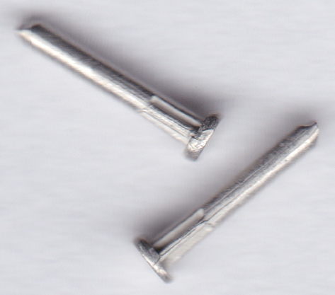 They are cold-headed from brass wire and tinned, so dimensions will vary a bit. Measuring several I found: Head diameter. As Brian found the heads are not round. The smallest size across any heads was 1.55mm. The largest across any heads was 1.74mm. But mostly they are in the range 1.60 - 1.65mm across. Head thickness. Measurements range from 0.48mm to 0.53mm. Pressing a few firmly into Veroboard, trimming and filing flush on the underside, they are proud by 0.51mm. The desired rail lift is 0.58mm, so this is perhaps a fraction thinner than I was hoping for, although it does leave a couple of thou for the solder. The shank diameter ranges from 0.89mm to 0.93mm. So drilling 0.90 or 0.95mm holes rather than 1.0mm would make a firmer fit, and may cause the heads to stand slightly more proud. The ribs under the head are tapered and difficult to measure. Immediately under the head they are about 1.3mm across for a grip in the holes. The overall length is 6.5mm (1/4"). After so much advance in electronics over the last 40 years it is strange to see these still easily available and seemingly the same as before. regards, Martin. |
||||
|
posted: 2 Jun 2015 20:24 from: madscientist click the date to link to this post click member name to view archived images |
Just be aware there are several variants of vero pins , the 1mm pin has a head dia of 0.98 and a head thinkness of 0.7 Full dimensional drawings are on the vero site tolerances are 0.15 mm A better fit perhaps Like you Martin. I'm experimenting with different substrates for vero pins. Including plain 1.5mm fr2 ( Paxolin ) which I can cut in a cnc milling machine or using them with ply sleepers instead of rivets, the idea being to use a few sleepers at critical strong points and gain the advantage of soldered construction with the appearance of fully functional turnout build methods |
||||
| Last edited on 2 Jun 2015 20:41 by madscientist |
|||||
|
posted: 2 Jun 2015 21:00 from: Martin Wynne
click the date to link to this post click member name to view archived images |
madscientist wrote: Just be aware there are several variants of vero pins , the 1mm pin has a head dia of 0.98??? I'm a bit puzzled how a 1mm diameter pin can have a head diameter of 0.98mm? The pins from RS are Vero type 18-1660: http://www.verotl.com/en/product/single-sided-terminal-pin-with-barbed-pressfit-retention-for-1.02-dia-holes.-vero-part-18-1660 For which this drawing shows a head thickness of 0.7mm: http://www.verotl.com/en/download/18-1660.pdf But the ones I have here do not comply with that. There are other 1mm pins on that site, for which the drawing shows a head thickness of 0.5mm, see for example: http://www.verotl.com/en/product/single-sided-terminal-pin-for-1.02mm-dia-holes-vero-part-18-0223 which have a serrated shank instead of twin ribs. Martin. |
||||
|
posted: 2 Jun 2015 23:50 from: madscientist click the date to link to this post click member name to view archived images |
Martin Wynne wrote:madscientist wrote:Just be aware there are several variants of vero pins , the 1mm pin has a head dia of 0.98??? Opps sorry , I meant. The 1mm pin has a shank of 0.98 |
||||
|
posted: 3 Jul 2015 21:48 from: polybear click the date to link to this post click member name to view archived images |
Hi Martin, Just wondering if you have done any more with the veropins you received? Cheers, Brian |
||||
|
posted: 3 Jul 2015 22:32 from: Martin Wynne
click the date to link to this post click member name to view archived images |
polybear wrote:Just wondering if you have done any more with the veropins you received?Hi Brian, Not yet. Workshop jobs are generally for the winter months. At this time of year when I'm not Templotting I like to be out walking with my camera: 2_031729_330000000.jpg 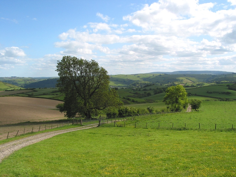 OS grid ref: SO 25820 77854 Martin. |
||||
|
posted: 3 Sep 2015 16:18 from: madscientist click the date to link to this post click member name to view archived images |
I have been playing with Veropins and ply sleepers, I was wondering about keeping them in place with high temperature adhesive that could withstand soldering. This is just for turnout construction as I like the ability to fettle the work that soldering gives Theres a 3M anaerobic adhesive that has a service temp of 230 C. should be fine for low melt solder Havent actually tried it yet , merely tried some veropins pushed into drilled holes on the ply. The alternative is something like superglue, but it means the pin cant be touched with an iron again. comments ? |
||||
|
posted: 3 Sep 2015 17:19 from: Jim Guthrie
click the date to link to this post click member name to view archived images |
madscientist wrote: Havent actually tried it yet , merely tried some veropins pushed into drilled holes on the ply. The alternative is something like superglue, but it means the pin cant be touched with an iron again.The Veropins usually have some sort of serration on the pin just under the head to make a tight fit in Veroboard holes so if you can use the same size of hole in your sleepers you might find that the serrations hold the pin in sufficiently well without the need for any adhesive. Jim. |
||||
|
posted: 3 Sep 2015 17:33 from: polybear click the date to link to this post click member name to view archived images |
Hi, I've had an experiment with vero pins here: http://www.rmweb.co.uk/community/index.php?/topic/69145-attention-00-sf-track-builders/page-4 (post #77) If you can build the turnout etc. "in-situ" on the baseboard, rather than as a separate panel on the workbench, then you probably won't have to glue them at all. I found that it was actually quite difficult to remove a panel from the building board - the friction of the multitude of pins being gripped by the mdf offcut I was building on was quite a surprise; I had to be quite careful not to damage the finished track panel during the removal process. It actually made me realise that it would be beneficial to cut the vero pins to match the thickness of the sleeper, or thereabouts, when intending to build items "off baseboard". HTH Brian |
||||
|
posted: 4 Sep 2015 18:35 from: madscientist click the date to link to this post click member name to view archived images |
I an using a kind of plumbers foam board that lets me push pins in easy. what I was concerned is that while they are a press fit, they might weaken over time and release from the ply | ||||
| Last edited on 4 Sep 2015 18:39 by madscientist |
|||||
| Please read this important note about copyright: Unless stated otherwise, all the files submitted to this web site are copyright and the property of the respective contributor. You are welcome to use them for your own personal non-commercial purposes, and in your messages on this web site. If you want to publish any of this material elsewhere or use it commercially, you must first obtain the owner's permission to do so. |