Templot Club Archive 2007-2020
|
|||
| author | remove search highlighting | ||
|---|---|---|---|
|
posted: 21 Oct 2020 23:37 from: DerekStuart
click the date to link to this post click member name to view archived images |
Evening all. I was inspired by the video here about the relaying of St. Pancras station throat, specifically where they showed the presses at the factories for bending things like turnout knuckles/ wings. That led to me resurrecting a broken pipe bender at work... I made a rudimentary copy for bending rails and it worked (sort of). But this would only work for straight turnouts. I am not an engineer nor mathematician, but I don't need to be- most of what we do can be copied in principle from the real railways. My question is this- whilst this is very simple for a straight turnout, for a curve- let us say 100Xr and then a knuckle bend of 10Xr you effectively have unlimited possibilities and I cannot believe they had limitless options for presses in the factories. Yes, I know the 'big blokes with big hammers' but I'm not sure that would work here. Does anyone know how they overcame this, please? I would like to design a simple jig that anyone can build from easy to get components. Thanks Derek |
||
|
posted: 22 Oct 2020 00:36 from: Martin Wynne
click the date to link to this post click member name to view archived images |
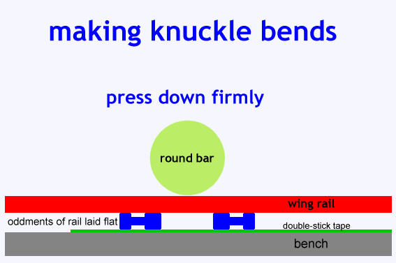
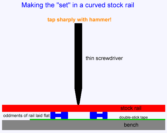
Hi Derek, I've posted these diagrams before, including in your previous topic on this subject: topic 2788 2_041828_140000000.png  2_041840_270000000.png  They could be worked up into a proper press tool with a depth stop to set the bend angle, etc., or as an attachment to a drill press. Note the above is for vertical rail. If you want to make horizontal bends in inclined rail you need a conical mandrel, the rail must be held firmly at the inclination angle (1:20), and a lot more force. It may require the rail to be annealed at red heat first. It might be possible to twist the rail from inclined to vertical in front of the bend, make a horizontal bend, and then twist the rail back to inclined beyond the bend. Making two twists and a bend in the space of a few mm, while keeping the running edge in line, would be tricky. The prototype uses rail twists in places -- for example in the vee rails just beyond the splice. Making those twists needs a press tool, so that the rail head remains in a straight line. cheers, Martin. |
||
|
posted: 22 Oct 2020 01:21 from: DerekStuart
click the date to link to this post click member name to view archived images |
Hello Martin Thank you. I am of course already aware of those two simple, but effective methods. I use the 'set' method and it works well. However, I've not managed to get consistent results for the knuckle/ wing bend- especially for the (L)NER which has a gentle bend. I did find bending them around a Hartley's Jam jar came out right for a 1:8 bend. However, if the turnout is curved then getting this bend in accurately becomes harder. Yes it can be manually checked against a Templot printout, but I find adjustments tend to end up leaving lots of irregular bends rather than one clear and gentle curve. I have a week off next week. I shall think up some ideas and try them- I've nothing to lose but my fingers and thumbs- oh, and pride. Thanks Derek |
||
|
posted: 22 Oct 2020 07:53 from: Hayfield
click the date to link to this post click member name to view archived images |
Don't forget the method of using the Vee filing jigs to form the bend,form the benb by eye slightly narrower, place the rail in the jig and tap with a hammer. Perhaps something similar could be formed ? |
||
|
posted: 22 Oct 2020 09:58 from: DerekStuart
click the date to link to this post click member name to view archived images |
Hello John I was thinking of a way whereby anyone- whether really experienced or a complete beginner- could be guaranteed to get the same results. Using the filing jigs doesn't produce a nice and gentle bend. Some of the real experts just put two slight bends by hand and it looks and works fine. This is just as much a question about the prototype as it is model. I've seen the video of the press they use for forming the knuckle bend, but given the infinite curves of real World turnouts how could they possibly have limitless formers for the presses? Derek |
||
|
posted: 22 Oct 2020 21:02 from: Julian Roberts click the date to link to this post click member name to view archived images |
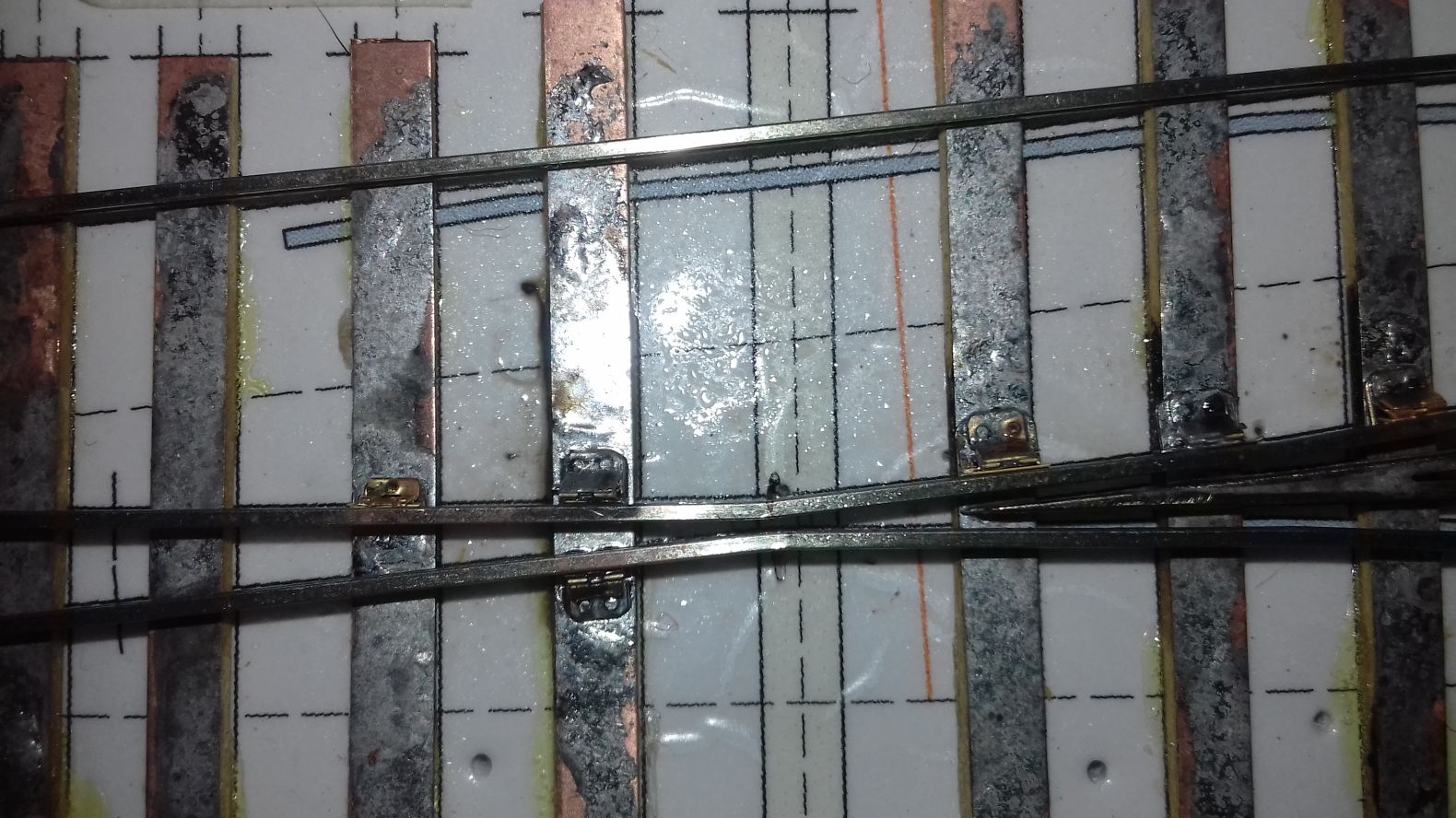
Hi Derek I'm wondering whether you're aiming for an unattainable perfection and whether it is the curve of the wing rails that is causing a problem. Here are mine for a 1 in 10 crossing. I bent them around some round nose pliers, that incidentally taper - each is a cone - not that I'm interested in trying to get rail inclination. I think they may be far from ideal but testing with a wagon gives nice sweet running. Surely it's the alignment that matters most for the running, and level? The latter can be crudely fixed after construction with a big file over the whole area. However apologies if I'm actually considerably under-qualified to make this suggestion. Anyway this photo is from my crossing making blog. I will give the link in an edit. http://www.scalefour.org/forum/viewtopic.php?t=7028 3591_221549_460000000.jpg  |
||
| Last edited on 22 Oct 2020 21:07 by Julian Roberts |
|||
|
posted: 22 Oct 2020 22:00 from: Ariels Girdle click the date to link to this post click member name to view archived images |
A problem I see with a jig is that it can't allow for the variation in materials. Bullhead from different suppliers will be softer/harder/springier etc. In my experience that can make a big difference to the exact bend you would end up with. You would almost certainly have to adjust by hand afterwards to get the angle exactly right. | ||
|
posted: 23 Oct 2020 03:04 from: DerekStuart
click the date to link to this post click member name to view archived images |
Hello Julian. I am quite familiar with your work and although I think we started off about the same time making turnouts, your progress has been far greater than mine. It's not the end of the World making this by jig, but I have found if using (L)NER practices- which has a far more gentle knuckle curve- errors are harder to avoid, both in terms of looks and running. Hello Ariels Girdle, yes you make a good point. However, I think an adjustable jig that can accommodate an infinite amount of curve options should also be able to deal with rail differences. I did wonder about its springiness though. It's easy to bend a rail to X curve, but if it is then going to spring back out to XX curve, it may be necessary to bend it to 1/2X etc. I shall experiment next week... and assuming Accident and Emergency department can re-attach my fingers and thumbs, I'll drop a line to let people know how I (didn't) get on. |
||
|
posted: 23 Oct 2020 23:36 from: Trevor Walling
click the date to link to this post click member name to view archived images |
Hello, I would suggest the angle can be varied by altering the distance between the oddments of rail laid flat shewn or shown in Martins diagram. The closer they are together the more acute is, or will be, the resulting angle. More acute angles will require more force or a bigger hammer. Consistency will require the same distance and force each time. A drill press may make that easier. Regards. Trevor. |
||
|
posted: 24 Oct 2020 09:13 from: Phil O
click the date to link to this post click member name to view archived images |
Trevor Walling wrote: Hello, Hi A machine vice could be used to give an infinite range of settings and by using the limiting stop on the drill press, you will always get a uniform deflection of the rail. You would need to make a tool to fit the chuck and possibly do a test piece each time you set up to make knuckles. A further thought on the tool, an old screw driver could have the handle cut off and the blade ground to suit. Cheers Phil. |
||
| Last edited on 24 Oct 2020 09:17 by Phil O |
|||
|
posted: 24 Oct 2020 15:41 from: DerekStuart
click the date to link to this post click member name to view archived images |
Thanks for the replies. The problem is (and maybe it's not actually a problem and as such I'm looking at solving a problem that doesn't actually exist) but if using the method outlined by Martin (and I write this with great respect for his knowledge and abilities) if one uses, for example, a 20mm diameter bar, one is getting a 5ft diameter curve by varying the length of that curve one will get something that lines up. But, in the case of a (L)NER 1:8 the diameter of the bar would need to be 64mm and such a gentle curve won't form when it's only a rail's width from the desk. Don't misunderstand me, I have used this method and it works- it's the same or similar to that used by the very best. I have also bent rails around a jam jar, but as mentioned above, sometimes the 'springiness' makes that hard. This was just as much a question about how the real companies solved this problem as it is about models. Producing 'standard' sizes is easy- just change the shape of the presses in the factories- but when turnouts could be built on an unlimited set of curves, that means the presses would need to accommodate that. 'Big blokes with big hammers' can curve a length of rail, true, but not over a short distance on a critical piece of infrastructure, surely? Thanks Derek |
||
|
posted: 24 Oct 2020 17:28 from: Martin Wynne
click the date to link to this post click member name to view archived images |
Hi Derek, I think you are finding difficulties where there are none. Most railway companies have only about a dozen or so standard crossing angles, and the crossing shop would keep a stock in hand of bent wing rails of each size sufficient to meet the usual needs arising. When setting up the press to make a batch of wing rails, the press would be adjusted to match the angle and bend radius shown on the drawing. The knuckles are assembled from a pair of wing rails using spacer blocks and bolts to set the knuckle gap (and hence the final bend radius at any given crossing angle). Where a crossing is to be laid into a ruling curve, the spacer bolts are slacked off, the rails are crowed to the required curve to fit the chairs, and the spacer bolts are re-tightened. The typical railway curve radius is so much larger than the knuckle bend radius that there is no significant change in the bend radius or knuckle gap needed to match the curve. Fishwashers are used under the bolts, and the spacer blocks have fish angles top and bottom. For the fishing to work as intended, neither the washers nor the blocks make contact with the rail web, and the fishbolt hole is drilled oversize through the web to clear the bolt (also to allow for the fact that the rail is inclined and the bolt is horizontal). The lateral bolt clearance means that there is no difficulty in curving the rails to typical railway radii. For the model, we don't have knuckle bolts and spacer blocks. The round bar mandrel needs to be smaller than the required finished bend radius. The spacing of the supports, and the pressure applied, is then adjusted by trial and error to give a result matching the template. With a bit of practice it can be done quite quickly. cheers, Martin. |
||
|
posted: 26 Oct 2020 15:19 from: DerekStuart
click the date to link to this post click member name to view archived images |
Thanks Martin Perfectly understood. It's still a case of 'big blokes with big hammers'. That surprises me, but I can see why/ how it would work. Many thanks Derek |
||
| Please read this important note about copyright: Unless stated otherwise, all the files submitted to this web site are copyright and the property of the respective contributor. You are welcome to use them for your own personal non-commercial purposes, and in your messages on this web site. If you want to publish any of this material elsewhere or use it commercially, you must first obtain the owner's permission to do so. |